-
Hi,
I am aiming to convert a CRT oscilloscope into an LCD oscilloscope by converting the video signal to VGA using an FPGA. The incoming video format is similar to VGA but uses different timing and voltages.
The pixel clock (ie time per pixel) etc for VGA is at a different rate to the incoming video signal. Therefore my incoming signal is not synchronised in any way with my outgoing video signal except that they are both 60Hz. I'm trying to figure out the best way to deal with this situation.
I was thinking what I could do is have two banks of memory. The incoming frame writes to the banks alternately, and the outgoing frame reads from the banks alternately, such that we never read from a bank at the same time as writing to it. But this assumes that I can keep both displays completely in sync (they are both operating at 60hz). I would then have two different pixel clocks (outgoing and incoming) and the banks of memory would switch between the two clocks and I don't know if this is a good idea?
Is there a better architecture for converting between the two video signals? -
Yes, you have the right idea. But in practice the sync rates will never be exactly the same.
So you will need to treat them as asynchronous. You'll need at least 3 framebuffer slots to do rate conversion. Then add some very simple logic to increment ecah domain's FB ptr at each frame completion. -
Worse yet. If the input clock is faster then you should be able to skip some of the frames. If the input clock is slower you should be able to output the same frame twice. If the clock frequency varies over time you should be prepared to do either of these.
-
Yes, you have the right idea. But in practice the sync rates will never be exactly the same.
So you will need to treat them as asynchronous. You'll need at least 3 framebuffer slots to do rate conversion. Then add some very simple logic to increment ecah domain's FB ptr at each frame completion.
Why three frame buffers? How would you work with them? -
It can be done on several ways:
Using multiple frame buffers is one possible solution but requires an memory and may generate artefacts with changing screen content due to skipping/replicating frames.
If the output video timing must not match VGA exactly, you can choose a similar timing and fine tune/correct/sync the timing by skipping pixels or lines during blanking interval. This works fine for most TFT LCD panels and DVI/HDMI output, but may create problems for a true VGA output because of the PLL used for recovering the pixel and line clock in monitors. If input and output timing are close enough maybe a small linebuffer FIFO is sufficient, removing the need for an external memory. -
Yes, you have the right idea. But in practice the sync rates will never be exactly the same.
So you will need to treat them as asynchronous. You'll need at least 3 framebuffer slots to do rate conversion. Then add some very simple logic to increment ecah domain's FB ptr at each frame completion.
Why three frame buffers? How would you work with them?
Triple buffering reduces the frame lag - it is in either of these states:
- One being filled
- One being displayed
- One waiting to be filled.
Or
- One being filled
- One waiting to be displayed
- One that is being displayed
It is used a lot in the software world to get the highest frames per second rates for interactive graphics, as the graphics H/W is never idle waiting for a buffer to come free.
(However, I don't that it is really applicable here).
-
Great, that's more or less the approach I thought I would go for. My next question then is, if I have these three buffers as three BRAMs in my FPGA, and I have my input pixel clock and my output pixel clock (operating at different frequencies), is it ok to just switch the BRAMs between the two clocks depending on who is accessing it? Or should I have a fast master clock that the BRAMs run on and then in some way interface this to the slower pixel clocks?
[edit] In reality, the amount of memory I would need looks to be way more than is possible via BRAM using a reasonably priced FPGA (3 640x480 frames at 3 bits per pixel). How should I structure the memory best for this? Would a chip like this be the right approach? http://www.alliancememory.com/pdf/dram/16M-AS4C1M16S-C&I_v2.0_March%202015.pdf [/edit] -
All modern FPGAs have true dual-port BRAMs. Just port A to your source domain (scope), and port B to sink domain (vga output).
However, it gets even easier if you can directly drive a panel digitally. Then you can feed it any pixel clock and any sync rate.
I've used this one: http://www.ebay.com/itm/361190698316
If you want I can give sample schematics and power supplies.
-
The pixel clock (ie time per pixel) etc for VGA is at a different rate to the incoming video signal. Therefore my incoming signal is not synchronised in any way with my outgoing video signal except that they are both 60Hz.
What is the actual timing of your signal? What VGA display(s) do you want it to be compatible with? -
I don't actually know the exact timings for the signal but I have some oscilloscope captures here: https://keepdevelopingprojects.wordpress.com/2016/01/25/project-crt-oscilloscope-lcd-mod-motivation/
I want it to be compatible with a 640x480 60Hz VGA signal -
Or.... you can go the other way. Try getting a cheap flat-panel VGA input and lower it's crystal clock at the same ratio 31.5:25. Feeding the video in now, the monitor will think it's actually 31.5Khz by 75Hz.
Also, any old Comodore Multisync screens which supported 15Khz through 36KHz on the horizontal will work directly with this logic analyser output.
A stupid dumb FPGA based line doubler, using an Analog Devices VGA ADC, with a bottom end 15$ Altera FPGA using 2k x 8bit dual-port ram for double each line coming out to a resistor ladder video dac will make a 50Khz X 60Hz video mode of 500xYYY(double your source) (horizontal res is meaningless here, you can call this 640 pixels or 1024 pixels) which is supported by any flat panel today.
I don't really want to risk damaging the scope and I also want it to work with any VGA monitor so I would rather do proper conversions. -
Can anyone recommend an ADC? I only need 4 bits maximum, single channel, probably at least 15MHz sample rate.
I was looking at the ADC1175 http://www.ti.com/lit/ds/symlink/adc1175.pdf but it looks kind of complex. -
With that ADC, you will need a long period PLL clock generating circuit tied to the H-Sync. But if you don't want to deal with an ADC with I2C controls, I understand.
Could you suggest an ADC that would not require a PLL? I don't really want to deal with a PLL either.
Is there no way that I can just manage the clock timing with the FPGA? Does the clock really need to be in phase -
I would wire this to a FPGA which has at least enough internal ram for 5 lines of video, since you are using monochrome, that makes 1kx8 per line x 5, or 6kx8 to be safe. The FPGA will need 1 pll to 2x the clock since you will be making a simple dumb line doubler. IE, 24Khz video in, 50Khz out, the vertical 60hz will remain the same. You will need an 8 bit DAC (unless you are feeding a panel digitally), or resistor DAC with a video opamp to feed the RGB analog in of an LCD screen and a logic buffer to convert the 3.3v sync out of the FPGA to 5v ttl as not all LCD screens like 3.3v.
How would that work?
I'm assuming when he says "CRT scope", he means a traditional scope with arbitrary X-Y-Luma vector drive (where a lissajous circle is drawn by moving the CRT beam in a circle, not by a progressive scan of the screen in Luma-H-V style). -
Ok, we got a problem here: After writing and deleting all those posts I made which were correct, and are now gone!I would wire this to a FPGA which has at least enough internal ram for 5 lines of video, since you are using monochrome, that makes 1kx8 per line x 5, or 6kx8 to be safe. The FPGA will need 1 pll to 2x the clock since you will be making a simple dumb line doubler. IE, 24Khz video in, 50Khz out, the vertical 60hz will remain the same. You will need an 8 bit DAC (unless you are feeding a panel digitally), or resistor DAC with a video opamp to feed the RGB analog in of an LCD screen and a logic buffer to convert the 3.3v sync out of the FPGA to 5v ttl as not all LCD screens like 3.3v.
How would that work?
I'm assuming when he says "CRT scope", he means a traditional scope with arbitrary X-Y-Luma vector drive (where a lissajous circle is drawn by moving the CRT beam in a circle, not by a progressive scan of the screen in Luma-H-V style).
@sokoloff, did you even look at the OT's scope in his thread:
https://keepdevelopingprojects.wordpress.com/2016/01/25/project-crt-oscilloscope-lcd-mod-motivation/
It's a digital driven display logic analyzer with old 25Khz video CGA driving a monochrome CRT which he want to convert to a format compatible with a modern LCD screen, whose video formats which start at 31.5Khz VGA.
-
Ok, we got a problem here: After writing and deleting all those posts I made which were correct, and are now gone!
@sokoloff, did you even look at the OT's scope in his thread:
https://keepdevelopingprojects.wordpress.com/2016/01/25/project-crt-oscilloscope-lcd-mod-motivation/
It's a digital driven display logic analyzer with old 25Khz video CGA driving a monochrome CRT which he want to convert to a format compatible with a modern LCD screen, whose video formats which start at 31.5Khz VGA.
@MattHollands, I'm sorry, but, @sokoloff messed me up and I deleted the original correct answers I gave you to your inquiry.
If you want to make a video scan doubler for your 'logic-analyser', (it's not really a scope as it says 'logic analyser' right on the top left of the device), start by taking a look at Texas Instruments TVP7002.
https://www.digikey.com/product-detail/en/texas-instruments/TVP7002PZP/296-22891-ND/1765836
Trust me on this one, don't worry that this IC has 3 parallel digitizer, if this chip is too complicated for you to build a circuit board around, then this a video scan rate converter / format converter is over you head. If you want to know more? why? Just ask and I'll re-write some of my deleted descriptions.
-
Ok, we got a problem here: After writing and deleting all those posts I made which were correct, and are now gone!
No, I only read half the internet tonight and that wasn't in the half I read...
@sokoloff, did you even look at the OT's scope in his thread:
https://keepdevelopingprojects.wordpress.com/2016/01/25/project-crt-oscilloscope-lcd-mod-motivation/ -
If you want to make a video scan doubler for your 'logic-analyser', (it's not really a scope as it says 'logic analyser' right on the top left of the device)
If you already have FPGA, it might be easier to build your own logic-analyzer front-end than to interface analog video signal. -
I don't think so. Did you see the picture of this guys logic analyzer/digital oscilloscope combo?If you want to make a video scan doubler for your 'logic-analyser', (it's not really a scope as it says 'logic analyser' right on the top left of the device)
If you already have FPGA, it might be easier to build your own logic-analyzer front-end than to interface analog video signal.
It's worth his time and a worthy project.
The TVP7002 does all the video interface work for him, he just needs to set a few I2C commands to set the horizontal resolution and he will be fine.
The FPGA will just double each line coming out of the TVP7002 as 2x speed. Easy enough with a 2:1 PLL setting in the FPGA and 2x 1kx8 dual port ram line buffers.
He only needs 8 bit monochrome. A bottom end 10$ fpga will be overkill. If he has any skill with Altera or Xilinx, and he has no trouble with a little MCU to set the I2C controls of the TVP7002, he can convert his current approximate video res of 512x384 to 512x768. Basically 1024x768, every pixel 2x wide by 2x tall. (Note that the extra pixels around the border of the logic analyzer's specked 500x240 could just be called a black border over-scan...)
-
Sorry it's been a long while! I've been a bit busy, but I've made progress with this.
I wanted to test your theory about line doubling, so I used an FPGA to simulate the signals if I doubled the horizontal frequency and you're right the display locks onto the signal
I also like your plan to use the TVP7002.
I'm thinking of using the Lattice LCMXO1200 FPGA. It has 1PLL, comes in a nice QFP package and has 9.2Kbits of EBR RAM which is enough for about 6 horizontal lines. Plus, it is pin compatible witht he LCMX02280 which has 3 times the ram and two PLLs if I need it. Does that sound reasonable then? -
Hi,
You can keep both displays in sync. TFT screens allow a wide range of their clocks and synchronisation signals. I have done these kind of conversions several times already. I prefer to use a Xilinx 9500XL series CPLD because these don't need an external config storage and have 5V tolerance. If the incoming and outgoing rate can be made synchronous (no form of interlacing) you don't need any storage.
I am aiming to convert a CRT oscilloscope into an LCD oscilloscope by converting the video signal to VGA using an FPGA. The incoming video format is similar to VGA but uses different timing and voltages.
The pixel clock (ie time per pixel) etc for VGA is at a different rate to the incoming video signal. Therefore my incoming signal is not synchronised in any way with my outgoing video signal except that they are both 60Hz. I'm trying to figure out the best way to deal with this situation.
I was thinking what I could do is have two banks of memory. The incoming frame writes to the banks alternately, and the outgoing frame reads from the banks alternately, such that we never read from a bank at the same time as writing to it. But this assumes that I can keep both displays completely in sync (they are both operating at 60hz). I would then have two different pixel clocks (outgoing and incoming) and the banks of memory would switch between the two clocks and I don't know if this is a good idea? -
You can keep both displays in sync. TFT screens allow a wide range of their clocks and synchronisation signals. I have done these kind of conversions several times already. I prefer to use a Xilinx 9500XL series CPLD because these don't need an external config storage and have 5V tolerance. If the incoming and outgoing rate can be made synchronous (no form of interlacing) you don't need any storage.
What do you use for memory? -
If needed I use an external SRAM. This is a board I made to convert an STN dot matrix LCD into TFT:You can keep both displays in sync. TFT screens allow a wide range of their clocks and synchronisation signals. I have done these kind of conversions several times already. I prefer to use a Xilinx 9500XL series CPLD because these don't need an external config storage and have 5V tolerance. If the incoming and outgoing rate can be made synchronous (no form of interlacing) you don't need any storage.
What do you use for memory?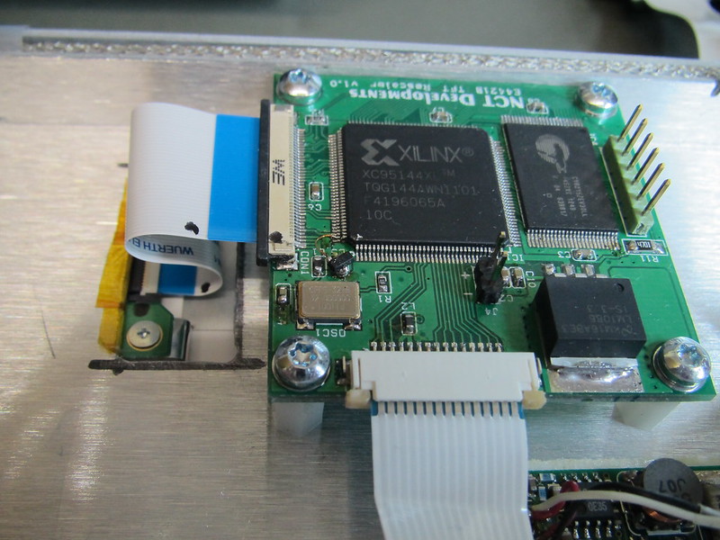
-
If needed I use an external SRAM. This is a board I made to convert an STN dot matrix LCD into TFT:
I will definitely need some memory and it will be easier if it is dual port (or two devices) so I will probably just go with the FPGA solution. But I appreciate your advice. -
Check out Altera's MAX10 devices. No bootprom and plenty of ram for 8 bit grey, multiple lines, or you can oversample and not worry about the PLL phase fine tuning, an all in 2.5 chip solution. 1 Max PLD, 1 Video ADC, + DAC, or parallel digital out to panel.
Too many IOs for your needs, 144 pin TQFP,
https://www.digikey.com/product-detail/en/altera/10M02SCE144C8G/544-3098-ND/5284822