-
Hi folks,
I have a pulse ox at home for med reasons and thought it may be fun to try and build a spare rudimentary one since I have access to the sensors and wanted to hack something together using an Arduino Uno R3, Raspberry Pi and Xprotolab.
I would like any thoughts and tips that might help. Here is my plan. The specs on the sensor pinouts are available...uses an RS232 9-pin cable but only a few pins are used to light up the 2 LED's, read off the photosensor and ground. I do not know the voltage but I can try and measure off the pulse ox and see what it pushes out on the pins, or I can assume what may be used for these LEDs.
I can use the Arduino with software-oscilloscope or Xprotolab to sniff around for the signal coming off the sensor which should give me a basic pulse reading. However the oxygen saturation is a ratio of some kind based on the 2 LED measurements, and so I would like to actually figure that out.
1. If 2 LED of different wavelength are used, and one sensor, then it must be flashing the LEDs alternately and reading the value, otherwise the sensor would pick up both lights at same time
2. The values are somehow averaged over time, that is why it must take a few seconds for the meter to figure things out and why it is delayed usually to real status of the blood
3. The circuitry looks more complex usually when it comes to these sensors, so can it be figured out or calibrated through software alone or do I need extra hardware before sending inputs into my boards?
I think I will end up using Arduino analog inputs, and maybe having Arduino send the data over to the Raspberry Pi maybe to do graphing, charting and realtime display. The xprotolab would be mostly to analyze the signal and reverse engineer what is going on.
Any advice or technical specs from someone familiar or works/designs pulse oximeters would be much appreciated!!!
Sincerely,
Edy -
I read up a bit more on how it works. Appears that the red and IR led are "back to back" and driven by one pair of pins. Forward voltage activates one led, reverse activates the other. This cycle back and forth sending pulses to the leds is coupled to reading the sensor, so it picks up light coming through for each specific led separately since there is only one photodiode.
Also, the photodiode is read between pulses to form a baseline signal indicating ambient light levels, which is subtracted.
The photodiode needs a current to voltage converter, then the voltage can be read and processed with algorithms to figure out the rest.
A bunch of filters are needed and also wondering how best to drive the leds since I'm not sure on the voltages needed and resistors for the setup. -
I don't know anything about this, but HackaDay has had a few pulse oximeters posted.
-
EnergyMicro does a decent basic write-up on a pulse oximeter.
http://blog.energymicro.com/2012/11/21/create-a-simple-pulse-oximeter-with-tiny-gecko/ -
Wow, talk about timing. I just got out of the hospital with a bad case of pneumonia and I nabbed the disposable pulse oximeter lead they were going to throw away.
And before you ask, yes I know for sure it was disposable because the sensor was embedded in a extremely sticky bandage and have seen this type thrown away before as soon as they were removed. I priced the lead out and it was $10 from a medical supply store. This one is a Nellcor.
New:
With bandage removed:
Pinout
9 phototransistor cathode green wire
5 phototransistor anode white wire; phototransistor detects level of IR and/or red light transmitted through the finger
7 shield cable shield, connects to copper shield over the phototransistor
2 LED1 red wire; anode of the IR LED, cathode of the red LED
3 LED2 black wire; cathode of the IR LED, anode of the red LED
-
Yes, that's exactly it. The ports are these 9-pin RS232 types and pinouts as you mentioned. Seems most instructables have no problem reading a pulse wave off the sensor. I assume the LED are driven by 5V with a resistor to limit amps, I am guessing if they are like most LED they have a 2V drop so you would use maybe 150 ohm resistor to keep it around 20mA so safe for your Arduino or RasPi GPIO pins.
The red and IR Led are wired in reverse, so you need a way to go 5V then -5V and back again, square wave, synchronized with your photosensor read. I guess you could wire to 2 pins and set one to HiGH and other to LOW, then alternate them.... That would be like doing Charie-plexing but with just 2 LED.
That should alternately light the 2 LEDs.
Then you need to read the photosensor... I am not familiar with these. Do they provide a varying voltage upon receiving light input? Do they need to be powered? Do you just hook them up to an Analog input and read it? I have to read up on that... Anyone here able to explain?
Finally, once we figure out how to alternate the LEDs and read the sensor, there is some formula to calculate the ratio between the 2 LED absorptions to calculate oxygen sat... That is the hard part, but I would be happy just to get by the first step. It appears we need some Op-Amps to handle the other steps... I have schematics but don't understand everything going on in there.
Hope for some more feedback or to work together to figure this out! Looks like more of us are being exposed to this medical device and learning this really is a fun project that seems fairly accessible and provides the chance to learn about some important aspects of electronics (circuit, LED, sensors, filters, op-amps, etc.). -
I'm trying to figure how you'd alternate ground between the pins. Maybe diodes connected to two transistors that flow when high on the pin. Maybe. I'm just guessing.
I was able to read some ohms off the "photo transistor" which I was just assuming was a standard Cadmium Sulfide cell, but the ohms reading didn't seem to line up with the amount of light. -
You don't have to alternate ground pins, you use a technique known as charlie-plexing which will led you run 2 LED from one pair of pins because you can alternate which one is HIGH and which one is LOW. When you have HIGH/LOW it runs one of the LED, and when you switch from LOW/HIGH then it runs the reverse-LED. The LOW pin is treated as a ground.
Heres some basic info:
http://www.instructables.com/id/Charlieplexing-with-the-Raspberry-Pi/
You just hook up a resistor and the 2 LED in different directions. Now as far as the pulse-ox goes, there are 2 LED in there it is just that one is visible and the other infrared, but the idea should still work because the schematics say it is coming from pin 2 and 3 of the cable, so you would hook those up to 2 GPIO pins on the Raspberry PI, or to 2 digital pins on your Arduino.
By the way, I found this interesting article:
http://www.ni.com/white-paper/14248/en
Now the other problem is what kind of "PHOTO" sensing element is in the sensor? Do all sensors use phototransistors, or do some use PHOTODIODE, PHOTOTRANSISTOR or PHOTORESISTOR. I found an interesting thread here:
http://www.societyofrobots.com/robotforum/index.php?topic=7331.0
Looks like the pinouts show it is a photoTRANSISTOR which should then change the amount of current going through, very different from measuring resistance or even voltage which would be the most ideal for using Arduino Analog INPUT (which measure voltage based on 0-5V range or AREF).
This problem is not new... I see a million posts on how to read phototransistors using Arduino and it seems it is not as easy as it looks. We may need additional electronics to amplify and filter the signal from the phototransistor as it may be very low and noisy. Here are some solutions I found which seem to work with not much but resistor parts, but I have a feeling we will need more to get something useful for the oxygen sat reading:
http://arduino.cc/forum/index.php?topic=50243.0
The schematic which seemed to work in the above thread was this:
Looking at some DATASHEETS for phototransistors (like this one here... Figure 6):
http://www.everlight.com/datasheets/PT334-6Cnew_datasheet.pdf
To in Figure 6 (on page 5) there are some curves showing collector current versus collector-emitter voltage, and there are several lines showing "Ee = 1.50mW/cm2" and so on. I assume that is the light intensity falling on the device, so you are seeing different curves characterizing what happens with the current/voltage at different light intensities.
My understanding from this datasheet is that you POWER the phototransistor with different voltages (like 1, 2, 3, 4 volts....) and you will get the Current flowing through depending on the light falling on the sensor (the different Ee curves). Notice that in the schematic above the test point is between the +5V and GND so it is acting like a voltage-divider, maybe so that instead of putting the full 5V through the device, the resistor helps reduce the voltage.
The phototransistor varies the current and the Arduino measures voltage. Therefore we need to convert current to voltage. Therefore, we need an Op-Amp as illustrated in many of the pulse oximeter schematics I've seen, as follows:
http://en.wikipedia.org/wiki/Current-to-voltage_converter
Hmmm.... the plot thickens.... But it's nice to learn all this stuff in the process!!!
-
I found this thread:
http://arduino.cc/forum/index.php?topic=117486.0
So I guess the basic understanding is that if you have a known voltage being supplied (say 5V) and you place a "shunt" resistor to ground with ohm rating that will be chosen for whatever the MAX current you want to measure (and what will be safe for the Arduino or RasPi)... like 500 ohm (assuming), then according to V=IR the maximum current possible should be V/R=I=5/500=1/100=0.01A or 10mA.
Then you measure the voltage across the shunt resistor using one of your Analog INPUT pins, as shown in this thread:
http://arduino.cc/forum/index.php/topic,6378.0.html
And in this image...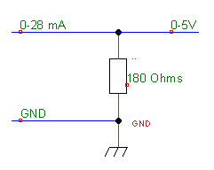
Another useful link is here:
http://itee.uq.edu.au/~emami/metr2800/ and http://learn.parallax.com/node/258
About half-way down the page we have a nice image:
So this sort of explains the entire concept more clearly now. Since the phototransistor has to supply electrons in the form of a current, and the resistor you are measuring across is FIXED and KNOWN, then the voltage across the resistor is directly proportional to the current according to V=IR. The phototransistor is a current-source and you are measuring the current indirectly by measuring the voltage across the resistor.
If the phototransistor goes from 0-20mA depending on the intensity of light, and you supply it 5V, it will act as a current source supplying anywhere from 0-20mA. Now you want to get a value that ranges from 0-5V on your Arduino analog input pin, so you figure at maximum 20mA current you will need a resistor with V=IR or V/I=R=5/0.020=500/2=250 ohm resistance.
So we have a situation where potentially up to 20mA of current can pass through the phototransistor, the "shunt" resistor at 250ohm running through 20mA will give a voltage of V=IR=0.020 x 250= 5 V. If you put in a 1k ohm resistor, then passing through 20mA maximum you would get V=IR=0.020 x 1000 = 20 V so that would be too high for the Arduino to measure. Then you put in a 100ohm resistor, V=IR=0.020 x 100 = 2 V so that would be in the range for the Arduino but not making full use of the resolution.
Almost "counter-intuitive" that the higher resistor would give you bigger voltage changes, and thus more sensitive to light than the lower resistor which would give you smaller voltage changes, and less sensitivity to light. Someone try to explain that one out in a way that is easy to understand, I would appreciate it!
By the way, I found a nice Op-Amp reference book (hundreds of pages) for something to read:
http://www.ti.com/lit/an/slod006b/slod006b.pdf
Looks like the next step is to figure out how to wire in an Op-Amp to improve the signal strength and remove "noise" since 0-20mA is a very small range of fluctuation where the noise is likely to really be messy (we will find out how bad it is once we graph the output of the Arduino and see what it looks like). -
Sorry, one last follow-up.....
I found this site useful:
http://healthcare.analog.com/en/patient-monitoring/pulse-oximetry/segment/health.html
I've ordered a few FREE SAMPLES from the company Analog Devices, primarily FET-Op-Amp and a band filter, so I'll keep you posted on how it goes. This may be useful in amplifying and stabilizing the current over time (as integrates and smooths it) and also reducing the noise level. -
Hi Edy, thats really fabulous research that you have put together. Have you finished the project?
I am also building pulse oximeter with Arduino. So far I understand the basic functioning and principle behind it. Now I am working on getting my head aorund signal conditioning. Could you brief me on that part, do you have a documentation for your project?
Any help will be appreciated, thanks man..
cheers. -
I saw this TI part advertised recently:
http://www.ti.com/product/AFE4490
Reference design:
http://www.ti.com/tool/tida-00010
Circuit description and theory:
http://www.ti.com/lit/ug/tidu124/tidu124.pdf -
thanks JDubU,
that looks like good solution.
If I could find it in Berlin that would be great as I couldn't order it in Germany and also I wanted to keep the design as cheap as possible so still looking for other solutions
thanks again -
I just stumbled upon the same problem.
I also want to use an AFE4400.
But the main problem is: Where to get the calibration data from?
I know, that the Nellcor Oximax Sensor do have an additional EEPROM in the sensor plug. And in this EEPROM, there's the complete calibration look-up table for this sensor.
But I have no idea, what protocol/pins are used for this data.
Anyone any idea? I couldn't find any info about this on the net. -
Attached the old Pinout.
The newer Oximax version is compatible, meaning it also has the resistor.
This is why my guess would be, that they are using an I2C-EEPROM. Maybe with VDD additionally at Pin 1 and the I2C-Pins at the empty Pins 4+8.
But no idea, if this is correct, or what voltage is used. Not even talking about the data format...
-
I just stumbled upon the same problem.
I also want to use an AFE4400.
But the main problem is: Where to get the calibration data from?
I know, that the Nellcor Oximax Sensor do have an additional EEPROM in the sensor plug. And in this EEPROM, there's the complete calibration look-up table for this sensor.
But I have no idea, what protocol/pins are used for this data.
Anyone any idea? I couldn't find any info about this on the net.
This older app note from TI http://www.ti.com/lit/an/slaa274b/slaa274b.pdf has a bit more detail about what needs to be done to measure the blood oxygen. It also has a reference to a document from Dr. Neil Townsend, which you can find on the web, which goes through the workings of the two colour technique for measuring SpO2. If you want to measure SaO2 people usually use a 6 colour technique, and it may be invasively done. I don't know where you can find good material on that.
As for calibration, the only calibrator instrument I know of is an expensive gadget from Fluke. If you just want to verify that your hardware basically works, you could try strangling someone who has a probe attached. You'll have to bring them really close to death, though, as blood oxygen level takes a surprisingly long time to fall significantly.
-
I already read that document, but thanks for the link anyways.
As said, the basic principle is clear to me and no real problem. The only problem is how to read and interpret the calibration data from such a sensor?
I have not much hope anyone knows that in here. But maybe...
The problem is, to be accurate, every sensor has to be calibrated individually, as due to small tolerances during the LED production the spectral density of the LEDs has some slight variations.
Usually this is no problem, but for this application it is. Therefore the manufacturer measures every sensor and then stores the indivudual needed calibration data into the sensor.
Like that it also doesn't matter what spectral distribution the LEDs have. They can even have emissions on several different bands. The only thing needed is the corresponding calibration data, and then you're fine. -
I already read that document, but thanks for the link anyways.
I wonder if the EEPROM is really there to store calibration data or to defeat the compatible probe makers? I think this is a market, like BGM, where the machines are not too expensive, and the real money comes from the probes. The older Nellcor probes seemed to work OK without the EEPROM. They only need to be accurate over a fairly narrow range. If the SpO2 starts dropping substantially the exact reading no longer matters much.
As said, the basic principle is clear to me and no real problem. The only problem is how to read and interpret the calibration data from such a sensor?
I have not much hope anyone knows that in here. But maybe...
The problem is, to be accurate, every sensor has to be calibrated individually, as due to small tolerances during the LED production the spectral density of the LEDs has some slight variations.
Usually this is no problem, but for this application it is. Therefore the manufacturer measures every sensor and then stores the indivudual needed calibration data into the sensor.
Like that it also doesn't matter what spectral distribution the LEDs have. They can even have emissions on several different bands. The only thing needed is the corresponding calibration data, and then you're fine.
The main variability is the brightness of the LEDs. You can calibrate for that when there is no finger present. I think we found the photosensor's spectral response was a much bigger variable than the spectral output of the LEDs, but a no finger present test can allow for that too. The photosensors are pretty linear when connected to a reasonable performance transconductance amp, and the LEDs only run at one brightness, so their linearity is unimportant. The main thing is to implement the equations in Neil Townsend's notes correctly. I know at least some pulse oximeter makers just use the maths, and have no lookup tables (at least that's what they say).
-
Quote
I think this is a market, like BGM, where the machines are not too expensive, and the real money comes from the probes.
I don't think so. The probes are actually quite cheap. And the machines are actually very expensive...QuoteThe older Nellcor probes seemed to work OK without the EEPROM.
As said the older probes used a resistor to select one of several preprogrammed calibration curves. There they measured every sensor and then looked which preprogrammed curve matches best and then selected the selector resistance accordingly.
The big advantage of the EEPROM is surely that you can make new sensor designs which have a completely different absorption curves as they use other spectra. Like that you can use any sensor and the monitor always immediately knows how to correctly calculate the SpO2.
E.g. their new head sensor has such a completely different curve.
Well if you look at the absorption diagram depending on the wavelength, then it is clear that the absorption is very dependent on the emission spectra. Sure the Photodiode spectral response is just as important. But as described by Nellcor it seems the variability on the photodiode is much smaller than for the LEDs.
And as you do not use monochromatic light, it is also clear to me that any difference in the emitted light spectra gives you another R/IR ratio for the same SpO2 value.
And as I understand the principle the light intensity is not relevant for the R/IR calibration. You just want to have the light as bright as possible to have a better signal compared to noise and ambient. And then to adjust the LEDs intensity so as that they get about the same response. Then you anyway normalize the AC from the DC content and then calculate the R/IR ratio. -
And as I understand the principle the light intensity is not relevant for the R/IR calibration. You just want to have the light as bright as possible to have a better signal compared to noise and ambient. And then to adjust the LEDs intensity so as that they get about the same response. Then you anyway normalize the AC from the DC content and then calculate the R/IR ratio.
The actual light intensity is unimportant, and that's critically important, as it varies by a huge amount depending on the exact positioning of the probe and the skin of the user. I was surprised to find that black or white skin made almost no difference to the measurement, as darker skin seems to attenuate both frequencies by a similar amount. The relative intensity of the two LEDs is how you get the ratio, so you don't care about their actual output, as long as it is adequate. However, you do need to calibrate their relative outputs accurately. After a bit of tweaking after that old TI app note was published we got good results with a Nellcor probe and the Fluke test set. -
Quote
However, you do need to calibrate their relative outputs accurately.
As I understood it from the AFE44xx guide, you usually just normalize the values (AC/DC). Like that the different intensities of the two LEDs are not important anymore.
As the ratio AC/DC from the sensor remains constant, no matter how strong the LED is. But it is surely always better to have stronger LEDs.
But I made progress. Finally, in a manual of a Nellcor Monitor N595, there are the schematics!!! Unfortunately you cannot see the exact pinout there, but it's a 50/50 chance, as they are only using the two available empty pins.
What do they do?
They use an EEPROM for the Maxim 1-wire-Bus. So the EEPROM just needs a GND and the 1-wire connection. It also gets it's power over that thing. Didn't know this one before...
The big problem: Maxim also sells special EEPROM versions which are SHA-256 protected. And I bet my left arm, that Nellcor is exactly using these.
But I will get a Nellcor Oximax Sensor and at least have a test. The slight chance remains, that they are using an unprotected EEPROM. But I seriously doubt that...
EDIT:
Studied the schematics a bit more, and it seems they are also providing the 12V supply for the programming of PROMs.
So there's a slight chance that they are using PROMs. And there are no protected PROMs available for the 1-wire bus. If the minimum production price is what Nellcor was after, then they surely would have chosen PROMs, as they are much cheaper than the EEPROM versions, not talking about the protected EEPROMs.
Well I ordered an Oximax Sensor. I will then look, what kind of chip they are using.
Edit2:
I even saw that there are chinese "el cheapo" Oximax sensor clones available. This again pushes my hope, that they are not using protected memories.
Surely these cheap chinese sensors are not individually factory calibrated...LOL, I even doubt the word "calibration" does exist in the chinese language
-
Just a little update, as the sensor didn't arrive yet.
As I read now, Masimo is also using a 1-wire EEPROM for the look-up table in their newer sensors... -
Just some continuation, as maybe someone later is interested in this stuff, and so can find it in a search machine...
Finally the el-cheapo Oximeter-Sensor arrived from china.
It was a tough job to open up the cast sub-d plug without damaging anything...(needed half an hour just for that)
Finally this is how the internal PCB looks like (see attached pics). As you can see, it has a nice little 8-pin soic on it.
Had a short look, and the only possible ICs for that would be a DS2433 (and it's derivatives) or a DS2502.
One is a 4KBit EEPROM, the other a 1Kbit OTP EPROM.
So my guess would be, they did go for the OTP EPROM.
Finally the question has been answered:
Of the unused Pins on the DB9 connector Pin 4 is GND and Pin 8 is Data for the 1-wire.
But what is really strange is, that the SOIC is wired 180° around.
Meaning the data pin should be on pin3 of the SOIC and the GND on Pin4, but actually they are on Pin 7 and 8???
So either these are not "original" 1-wire chips. Or they used a batch which has been wrongly wired.
If these are not "originals" then they could anyways be of any type...
We will see this if I read it out.
Edit:
Ah, now, when I look at the strange setup with the diode and the cap, I just realized, how they did it. They just took a small uC to emulate a 1-wire-memory-device.
And the diode+cap is needed for the generation of the VCC of the IC.
I at least hope it is like that. And not that Nellcor is using some proprietary 1-wire stuff implemented in a uC for their sensors. Without knowing the protocol, one would then really be pi**ed...
But what really puzzles me is C2. It is a capacitor directly connected between Data and GND. Does this make any sense in a 1-wire device? Maybe just for filtering...
-
A short update:
Finally found the time to make a 1-wire adapter to use with Maxim's OneWireViewer software.
Tested it with a 1-wire Temp-Sensor and a 1-wire EEPROM: It works.
When I connect the chinese Oximax-Sensor, then it identifies itself as a DS2503 : A 512 Byte OTP EEPROM.
So what was actually more or less expected.
But I am not able to read out the memory as I always get a CRC16 invalid error.
First I thought that maybe with this adapter the uC on the Oximax PCB doesn't get enough voltage (as it is purely driven by the RS232C itself). But I had a look with the scope and the voltage drops only about 0.5V during the transfer. This shouldn't be hardly any problem.
Hmm, my current conclusion is either Nellcor is using a proprietary CRC function, or the Nellcor equipment doesn't use the CRC for verification and therefore the chinese manufacturer didn't implement a proper CRC16 function...
Calculating the CRC16 for 1-wire is surely a bit a more complicated function. So it could well be, that they didn't implement it. Maybe also not to drain too much power out of the capacitor during the transfer, if it is not really needed.
Unfortunately the OneWireViewer doesn't show the data, when the CRC is wrong...
-
It's great information about pulse oximeter. I'm using pulse oximeter device for pulse rate and SpO2 (oxygen saturation level). This device show accurate rate.
-
Interesting threat.
I also try to make a HR and SPO2 monitoring. I have all the hardware and I can plot the graphs of the IR and RED leds. Everything is good so far but HOW DO I DO the calculations inside a low-power microcontroller. In TI's SLAA274B there is a band-pass filter, zero-crossings (I thing the block diagram is wrong - zero crossing should be done after the BP filtering) and RMS calculations. All of these are too hard to make in a MSP430. That's why in all these App notes they send the data to a PC and the PC makes the calculations.
So, I'm stuck at this points. Any suggestions from you guys?
Cheers! -
Interesting threat.
All the calculations in that app. note are performed on the MSP430. Only the final results are sent to the PC for display.
I also try to make a HR and SPO2 monitoring. I have all the hardware and I can plot the graphs of the IR and RED leds. Everything is good so far but HOW DO I DO the calculations inside a low-power microcontroller. In TI's SLAA274B there is a band-pass filter, zero-crossings (I thing the block diagram is wrong - zero crossing should be done after the BP filtering) and RMS calculations. All of these are too hard to make in a MSP430. That's why in all these App notes they send the data to a PC and the PC makes the calculations.
So, I'm stuck at this points. Any suggestions from you guys?
Cheers!
-
Turns out an Open Source Pulse Oxymeter is A LOT more important than any of us realized.
From around 20:00 but obviously watch the whole thing to get the context. -
In the end, was anyone able to connect a Nellcor Pulse Oximeter to an Arduino, and get the calibration data from the OTP EPROM on DB-9 pins 4 and 8?
Also, what OP-AMP did you end up using to convert the current range to an Arduino-readable voltage range?
Many thanks in advance! -
Hi guys,
I'll try to resurrect this thread If I may.
I just got couple of SPO2 sensors from China. They were offered as "Compatible for Nellcor DS-100A Spo2 Sensor with Oximax Tech" and they are equipped with 9 pin DB9 female connector.
I managed to read their PROM using esp8266 nodeMcu board and sensor wired using previously mentioned connection - GND pin4 & DATA on pin8 of the DB9 connector. Despite they are both labeled with unique serial numbers, the data from their PROM is absolutely identical.
On the PROM request they both respond with following 8 bytes:Code: [Select]93 20 18 FF 0 0 60 51Where 0x51 was confirmed by the OneWire.crc8() function to be correct.
It turns out the contents of the memory were also identical:Code: [Select]Data is[0000h]: DE E0 E4 64 60 62 60 A8 B2 86 0 2 2 3 4 4 1 FE 7 2 FF 2F 34 9 4 8B C8 E 7F 69 D4 21
Data is[0020h]: 92 31 2C C2 78 3D 30 D6 A2 69 2F 93 FF B5 CC EB B8 D6 A2 23 AB A5 B6 F5 6B 55 30 B0 BF A5 E1 76
Data is[0040h]: C0 C7 3E 9D 21 80 DE ED 43 7D B8 2B 9 F3 21 20 B 9A E6 C6 3E A7 C0 17 CA 14 EF 3A 5F CF ED DC
Data is[0060h]: C9 5E 50 EE 3 7E 68 B8 1E 15 65 C8 E8 7A ED D6 17 47 76 AE 40 C2 A6 2 BD 84 74 4 50 C 1A E
Data is[0080h]: 2 7 80 A7 86 FE 2C 92 64 96 9A AA 97 4B CC DB 5C DD 44 A2 41 4C 69 27 71 FF FF FF FF FF FF FF
Data is[00A0h]: FF FF FF FF FF FF FF FF FF FF FF FF FF FF FF FF FF FF FF FF FF FF FF FF FF FF FF FF FF FF FF FF
Data is[00C0h]: FF FF FF FF FF FF FF FF FF FF FF FF FF FF FF FF FF FF FF FF FF FF FF FF FF FF FF FF FF FF FF FF
Data is[00E0h]: FF FF FF FF FF FF FF FF FF FF FF FF FF FF FF FF FF FF FF FF FF FF FF FF FF FF FF FF FF FF FF FF
Data is[0100h]: FF FF FF FF FF FF FF FF FF FF FF FF FF FF FF FF FF FF FF FF FF FF FF FF FF FF FF FF FF FF FF FF
Data is[0120h]: FF FF FF FF FF FF FF FF FF FF FF FF FF FF FF FF FF FF FF FF FF FF FF FF FF FF FF FF FF FF FF FF
Data is[0140h]: FF FF FF FF FF FF FF FF FF FF FF FF FF FF FF FF FF FF FF FF FF FF FF FF FF FF FF FF FF FF FF FF
Data is[0160h]: FF FF FF FF FF FF FF FF FF FF FF FF FF FF FF FF FF FF FF FF FF FF FF FF FF FF FF FF FF FF FF FF
Data is[0180h]: FF FF FF FF FF FF FF FF FF FF FF FF FF FF FF FF FF FF FF FF FF FF FF FF FF FF FF FF FF FF FF FF
Data is[01A0h]: FF FF FF FF FF FF FF FF FF FF FF FF FF FF FF FF FF FF FF FF FF FF FF FF FF FF FF FF FF FF FF FF
Data is[01C0h]: FF FF FF FF FF FF FF FF FF FF FF FF FF FF FF FF FF FF FF FF FF FF FF FF FF FF FF FF FF FF FF FF
Data is[01E0h]: FF FF FF FF FF FF FF FF FF FF FF FF FF FF FF 3 0 0 FE FF FF FF FF FF 19 0 0 FE FF FF FF FF
So nothing to match the serials on the labels of the cables.
Unfortunately neither of the crc functions (crc8() & crc16) does not return the same code as the one red from the device:Code: [Select]Data is[0000h]: Calculated CRC8:8D
Data is[0000h]: DS250x -> CRC8:87
Data is[0020h]: Calculated CRC8:4C
Data is[0020h]: DS250x -> CRC8:21
Data is[0040h]: Calculated CRC8:16
Data is[0040h]: DS250x -> CRC8:77
Data is[0060h]: Calculated CRC8:D7
Data is[0060h]: DS250x -> CRC8:DD
Data is[0080h]: Calculated CRC8:A2
Data is[0080h]: DS250x -> CRC8:F
Data is[00A0h]: Calculated CRC8:63
Data is[00A0h]: DS250x -> CRC8:FF
Data is[00C0h]: Calculated CRC8:39
Data is[00C0h]: DS250x -> CRC8:FF
Data is[00E0h]: Calculated CRC8:F8
Data is[00E0h]: DS250x -> CRC8:FF
Data is[0100h]: Calculated CRC:D3
Data is[0100h]: DS250x -> CRC:FF
Data is[0120h]: Calculated CRC:12
Data is[0120h]: DS250x -> CRC:FF
Data is[0140h]: Calculated CRC:48
Data is[0140h]: DS250x -> CRC:FF
Data is[0160h]: Calculated CRC:89
Data is[0160h]: DS250x -> CRC:FF
Data is[0180h]: Calculated CRC:FC
Data is[0180h]: DS250x -> CRC:FF
Data is[01A0h]: Calculated CRC:3D
Data is[01A0h]: DS250x -> CRC:FF
Data is[01C0h]: Calculated CRC:67
Data is[01C0h]: DS250x -> CRC:FF
Data is[01E0h]: Calculated CRC:A6
Data is[01E0h]: DS250x -> CRC:FF
But you can see how memory contents affect the received crc8 code. Unfortunately I wasn't able to confirm those codes with the crc() functions no matter what I was trying. Still I can confirm that the data is identical on every read cycle.
I hope this will help.
So, having this information does anyone knows how all that memory contents are structured and how to extract calibration data?
Cheers!
-
Due to the ratiometric calculation of standard pulse oximeters the sensors don't need calibration.
https://www.nxp.com/docs/en/application-note/AN4327.pdf -
Would the same be true for let's say Ti's AFE4490 based project? Or there will be additional steps required?
https://www.ti.com/lit/gpn/afe4490 -
Would the same be true for let's say Ti's AFE4490 based project? Or there will be additional steps required?
The same is true for any standard pulse oximeter. TI have a similar app note for their ICs.
https://www.ti.com/lit/ug/tidu475/tidu475.pdf
TI also make an AFE4490 dev kit that includes a DB9 "Nellcor style" finger clip sensor.
https://www.ti.com/tool/AFE4490SPO2EVM
The main thing you need is the R-SpO2 curve that suits your specific sensor (or use someone else's as "close enough").