-
Wenzel Low Frequency Circulator
Posted by
uofmrob
on 10 Aug, 2020 18:58
-
Hi Everyone,
I've been following the EEVBlog channel for ages. It has taught me a lot about what I know about electronics. I'm a PhD chemist by training, but my position is an instrumentation position where I need to be able to test and repair a lot of fancy expensive equipment. I'm currently trying to build my own electron paramagnetic resonance spectrometer at home. Part of the challenge is getting an inexpensive low-frequency circulator. I found this really cool design and I'm trying to learn about op-amps and build my own. I think that it could make a really cool YouTube video!
http://www.qrp.gr/circulator/RFDesign3.pdfThoughts?
Rob
-
-
Sounds ambitious! - what does an electron paramagnetic resonance spectrometer actually do?
-
#2 Reply
Posted by
KE5FX
on 10 Aug, 2020 22:58
-
Hi Everyone,
I've been following the EEVBlog channel for ages. It has taught me a lot about what I know about electronics. I'm a PhD chemist by training, but my position is an instrumentation position where I need to be able to test and repair a lot of fancy expensive equipment. I'm currently trying to build my own electron paramagnetic resonance spectrometer at home. Part of the challenge is getting an inexpensive low-frequency circulator. I found this really cool design and I'm trying to learn about op-amps and build my own. I think that it could make a really cool YouTube video!
http://www.qrp.gr/circulator/RFDesign3.pdf
Thoughts?
Rob
It's a nifty circuit, all right. An LMH6733 or AD8003 is a good fit. The same technique gets you a single-ended directional bridge that works down to DC, which occasionally comes in handy around the house.
Sounds ambitious! - what does an electron paramagnetic resonance spectrometer actually do?
See page 335 ("A simple magnetic-resonance spectrometer")
here. Same idea works with
proton precession.
Edit: actually they both use proton precession. For some reason I was misremembering the Scientific American project article in connection with paramagnetic electron resonance (EPR).
-
#3 Reply
Posted by
uofmrob
on 11 Aug, 2020 00:22
-
-
#4 Reply
Posted by
uofmrob
on 11 Aug, 2020 00:34
-
-
#5 Reply
Posted by
KE5FX
on 11 Aug, 2020 01:30
-
Yeah, I don't think an LMH67xx opamp is going to work very well on a breadboard.

With 1 GHz-class parts, your breadboards need to look more like
Yup! Same physics behind both. EPRs look at unpaired electron spin while NMR spectrometers look at nuclear spin. Electrons are a bigger magnet so they require higher excitation energy, but smaller magnetic fields to split the quantum spin states. The big research spectrometers that cost $1.6 million dollars can do this stuff among many other things (I wrote the introduction and sections on naturally occurring radicals and metals). Mine is just for the sake of seeing anything and learning in the process.
Very cool. I always wanted to build either the SciAm project or
Joe Geller's version but have never seemed to get around to it. If I had, I'd presumably remember what sort of particles it uses...
-
#6 Reply
Posted by
uofmrob
on 11 Aug, 2020 01:38
-
This was my first prototype using these op amps (with most of the bare wire replaced with insulated wire before I powered it up once I got the connectivity right).
https://www.mouser.com/ProductDetail/NJR/NJM2137D?qs=54bfbthyeuO6TvPIDHWJog%3D%3D Initially, I just powered it directly from my bench power supply, then I watched a bunch of videos and learned more about op amps and figured out that I needed to use my dual tracking supply in serial mode. I'm only shooting for a 25 MHz spectrometer. I've never built something like what you had in the photo. Is the copper plate the ground and then everything else is wired directly above the plate?
-
#7 Reply
Posted by
uofmrob
on 11 Aug, 2020 01:49
-
I built one of the cheap 1-30 MHz antenna tuners off of eBay for the coil matching and it works well. The basic layout will be the source going into port one, then the matching network and saddle coil with the sample in the middle of the coil in port 2, then an rf detector on port 3 and a 50 Ohm load on port 4. When the coil is well matched, there should be hardly any reflection to the detector in port 3. Then, when the magnet field causes the spins to go into resonance, the Q changes and you should see the signal as an increase in the reflected power.
-
#8 Reply
Posted by
uofmrob
on 11 Aug, 2020 01:53
-
At least that's how our big fancy EPRs work. But ours use microwaves (either 9 GHz or 34 GHz) and magnetic fields of 340 mT to 1.2 T.
-
#9 Reply
Posted by
KE5FX
on 11 Aug, 2020 02:33
-
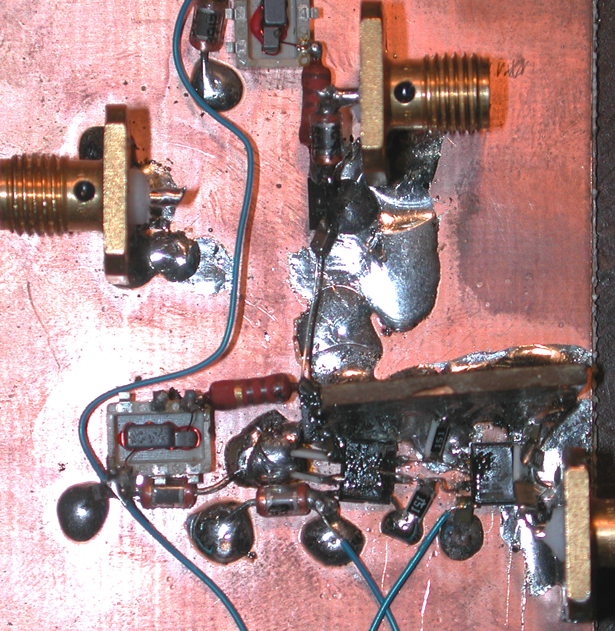
I've never built something like what you had in the photo. Is the copper plate the ground and then everything else is wired directly above the plate?
Yep. It's just a piece of unetched/undeveloped copper clad PC board material. Do a Google image search for
ugly construction or
dead-bug construction for inspiration. Some people like to carve islands and 'traces' in the foil with a Dremel tool, or employ additional bits of PCB material as 3D islands or standoffs, but none of that stuff is generally useful or necessary.
ICs built on modern semiconductor processes often contain transistors with frequency limits of 10 GHz or more, even when the IC itself is rated for use at much lower frequencies. So it doesn't matter what the intended frequency of operation for your project is, stray capacitance and inductance is almost always going to be a concern.
-
#10 Reply
Posted by
helius
on 11 Aug, 2020 04:48
-
The most common key word is "Manhattan construction", I think because the Trinity test electronics were done that way.
-
#11 Reply
Posted by
Brumby
on 11 Aug, 2020 07:48
-
The most common key word is "Manhattan construction", I think because the Trinity test electronics were done that way.
I thought it was because such construction ended up looking like Manhattan in miniature.
-
#12 Reply
Posted by
David Hess
on 11 Aug, 2020 10:38
-
I made a mock up on a breadboard and it didn't seem to work. I think I may have had op amps that aren't what I should have used. I have this one now and I soldered it to a 14 pin IC breakout board from Adafruit. It's a quad amp as I'm going for a 4 port circulator. I'm very much not an electrical engineer. I'll probably be back for lots of help from all of you experts!
Start out with a lower frequency version using lower frequency operational amplifiers. Fast operational amplifier will require ground plane construction and suitable decoupling.
-
#13 Reply
Posted by
uofmrob
on 11 Aug, 2020 11:17
-
Thanks for all the information everyone!
-
#14 Reply
Posted by
uofmrob
on 11 Aug, 2020 11:38
-
-
#15 Reply
Posted by
uofmrob
on 11 Aug, 2020 12:43
-
Start out with a lower frequency version using lower frequency operational amplifiers. Fast operational amplifier will require ground plane construction and suitable decoupling.
David, would you have a particular op amp that your would recommend for this project?
-
#16 Reply
Posted by
David Hess
on 11 Aug, 2020 15:53
-
Start out with a lower frequency version using lower frequency operational amplifiers. Fast operational amplifier will require ground plane construction and suitable decoupling.
David, would you have a particular op amp that your would recommend for this project?
I would need some idea of the maximum operating frequency. But even a few 10s of MHz should use ground plain construction as others mentioned; even if the application frequency is low, fast operational amplifiers are not. Forget using solderless breadboard for this. An expert might get away with point-to-point wiring on soldered breadboard at lower frequencies but Manhattan or dead-bug style construction will actually be easier to get working.
Maybe someone else has a better source, but pads for Manhattan construction are available here:
http://www.qrpme.com/?p=product&id=SAMAnother limitation is that the operational amplifiers will be required to drive low impedance loads which limits you to parts intended for 50 and 75 ohm applications. (1) In this case they have to drive their own medium impedance feedback network, the low impedance output network, and a second medium impedance output network all in parallel; so general purpose parts are not suitable.
I would probably start with something low cost which meets the above requirements like the LT1395, which also happens to work at +/-5 volts where less expensive parts are limited to lower voltages.
(1) "Fast" operational amplifiers generally meet this requirement because they need to be able to drive transmission lines.
-
#17 Reply
Posted by
uofmrob
on 11 Aug, 2020 16:27
-
Thanks so much for all the advice!
Rob
-
#18 Reply
Posted by
uofmrob
on 11 Aug, 2020 17:55
-
Another quick question....since I'm looking at building it as a four port circulator, is there a reason to avoid just going with an IC that has four amps in one IC as opposed to four separate ICs? Is there more of a chance of signal leakage with the amps all being in one chip?
-
#19 Reply
Posted by
KE5FX
on 12 Aug, 2020 01:24
-
Another quick question....since I'm looking at building it as a four port circulator, is there a reason to avoid just going with an IC that has four amps in one IC as opposed to four separate ICs? Is there more of a chance of signal leakage with the amps all being in one chip?
With the LMH6722 or LMH6733, crosstalk at 25 MHz will be in the -70 dB to -80 dB range (see figure 9 of the data sheet), so it will not dominate the isolation.
I'd favor the LMH6733 over the LMH6722 for this application,
unless you have a use for the fourth opamp. (edit: I see you want four ports, so, yeah.)
I'm not familiar with the LT139x family David mentions, but it looks fine as well. Not a fan of whatever those 'Manhattan' pads are that he mentioned, though, unless you just want to add some stray capacitance in random places. Current-feedback amps can be twitchy in that regard.
This bridge uses a very similar approach to Wenzel's,
as described by Sam Wetterlin (link is a mirror, Sam's site seems to have vanished):
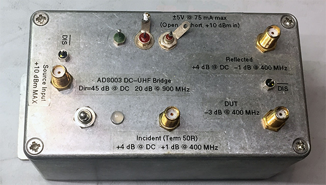

If you use good opamps and good construction practices, the achievable performance from this class of circuit is pretty awesome. With the AD8003 that I used, the directivity is still 20 dB at 900 MHz(!). The LMH6733 performs similarly.
-
#20 Reply
Posted by
David Hess
on 12 Aug, 2020 01:33
-
Another quick question....since I'm looking at building it as a four port circulator, is there a reason to avoid just going with an IC that has four amps in one IC as opposed to four separate ICs? Is there more of a chance of signal leakage with the amps all being in one chip?
Even if you ignore isolation between the operational amplifiers, the close confines around a dual or quad chip can make isolation between sections more difficult. Using single parts allows designing one "section" and then replicating it.
Not a fan of whatever those 'Manhattan' pads are that he mentioned, though, unless you just want to add some stray capacitance in random places. Current-feedback amps can be twitchy in that regard.
I have seen some better DIP and SO8 pads somewhere but the example I linked are what I was able to immediately find online.
-
#21 Reply
Posted by
KE5FX
on 12 Aug, 2020 01:44
-
Even if you ignore isolation between the operational amplifiers, the close confines around a dual or quad chip can make isolation between sections more difficult. Using single parts allows designing one "section" and then replicating it.
That's for darned sure.
I have seen some better DIP and SO8 pads somewhere but the example I linked are what I was able to immediately find online.

Just solder.
-
#22 Reply
Posted by
uofmrob
on 12 Aug, 2020 02:36
-
-
#23 Reply
Posted by
uofmrob
on 12 Aug, 2020 02:44
-
So without any pads, do you just glue the ICs upside down on ground plate and solder to the connectors?I can 3D print supports for the BNC connectors pretty easily and glue them down.
-
-
yes, I have bought the parts for this circuit a while back (I chose a very high speed op-amp but still in SOIC or MSOP, something with some kind of leads)
I need to etch a PCB. It is a interesting one.
if you are a chemist etch the PCB
-
#25 Reply
Posted by
uofmrob
on 12 Aug, 2020 02:54
-
I think I'm going to make a big order for all the stuff tomorrow and give it a whirl. Thanks so much for all the help everyone. This forum is such an amazing resource with so much knowledge and generosity!
-
-
So without any pads, do you just glue the ICs upside down on ground plate and solder to the connectors?I can 3D print supports for the BNC connectors pretty easily and glue them down.
Sometimes I super glue parts upside down and bend the leads down and solder them to ground but it depends on what part you have. IMO this kind of construction gets old after a while.. and it helps if you have precise hand tools.
The problem is if you have a thick ground plane, the chip and glue gets real hot when you are tacking the nearby lead to ground, so it could help if you pre-tin it. And you can glue copper to something, cut a hole out under a chip, then glue the chip not to the copper, so you don't have heat issues..
I found that its kind of harder then it looks, and you end up with messy construction unless you do alot of thinking.
-
#27 Reply
Posted by
uofmrob
on 12 Aug, 2020 03:00
-
Oh, and another question I had. For this type of circuit, should the ground be an earth ground?
-
-
i would power it off batteries. if you have a real circulator or isolator, they don't have any connection on them other then the ports. They are usually a passive magnetic element. I would design it as a module you can use on a RF bench with batteries so you can use it the same as a regular circulator to keep things simple and reliable on some AAs.
Once you setup some microwave assemblies you will be happy there is less wires.
those RF jacks connect to the RF equipment, which is usually connected to ground, by the connector on the chassis.
in a RF assembly typically you see a can with little solder feed through connections that the DC power goes into. I don't think its typically earthed?
-
#29 Reply
Posted by
RoGeorge
on 12 Aug, 2020 05:22
-
This was my first prototype using these op amps (with most of the bare wire replaced with insulated wire before I powered it up once I got the connectivity right).
https://www.mouser.com/ProductDetail/NJR/NJM2137D?qs=54bfbthyeuO6TvPIDHWJog%3D%3D
Initially, I just powered it directly from my bench power supply, then I watched a bunch of videos and learned more about op amps and figured out that I needed to use my dual tracking supply in serial mode. I'm only shooting for a 25 MHz spectrometer. I've never built something like what you had in the photo. Is the copper plate the ground and then everything else is wired directly above the plate?
You may want to look at the following prototyping techniques:
For high frequency, pick a method that uses a ground (copper) plane. Shielding might help a lot, too.
Solderless breadboards are to be avoided for high frequency circuits. Those breadboards produces unpredictable results, mostly because their internal traces have a lot of stray inductance, capacitance and high contact resistance. In breadboards, internal traces are in fact parallel sheets of metal.
-
#30 Reply
Posted by
uofmrob
on 12 Aug, 2020 11:33
-
Thanks!
-
#31 Reply
Posted by
uofmrob
on 12 Aug, 2020 12:55
-
I had actually just subbed to this channel. There's some great content! I had just watched all of the NanoNVA videos. I have a NanoVNA 2 coming soon to help with the coil design and matching. I have a super expensive Network analyzer at work, but I wanted to have one at home. Part of this project is to see how cheaply I can make an EPR. It's going to be baby steps, but eventually, I want to drive the source and magnet with a raspberry PI. There are a lot of these out there as people have linked above, but those are all based on the original instruments that detected the effects. I'm shooting more for a magnetic field sweeping spectrometer based off of the modern instrument designs, just operating at lower fields with off the shelf components. If I can get it to work well with relatively simple and inexpensive parts and methods, I'm probably going to present it at the Rocky Mountain EPR conference. You know, if it ever meets again.

-
#32 Reply
Posted by
uofmrob
on 12 Aug, 2020 14:06
-
OK, I ordered some individual op-amps and some copper clad boards. They should all be here Friday. It looks like I have a weekend project!
-
#33 Reply
Posted by
David Hess
on 12 Aug, 2020 20:03
-
So without any pads, do you just glue the ICs upside down on ground plate and solder to the connectors?I can 3D print supports for the BNC connectors pretty easily and glue them down.
What I generally do is anchor the package right-side-up above the ground plane using the decoupling capacitors between the ground plane and supply pins. Then I use either wire wrap wire or enameled copper to do point to point wiring.
However in a real layout, the equivalent of not using pads is to cut away the ground plane to raise the impedance which the above method does not allow whether pads are used or not.
-
#34 Reply
Posted by
uofmrob
on 12 Aug, 2020 20:12
-
I was thinking that for the places in the circuit where multiple connections come together, I would use my rotary tool and cut an island in the coper board
-
#35 Reply
Posted by
David Hess
on 12 Aug, 2020 21:56
-
I was thinking that for the places in the circuit where multiple connections come together, I would use my rotary tool and cut an island in the coper board
That is a common method; I still prefer to glue or solder a little pad down if I am not wiring things in the air. Strips of copper clad board can be used as controlled impedance transmission lines.
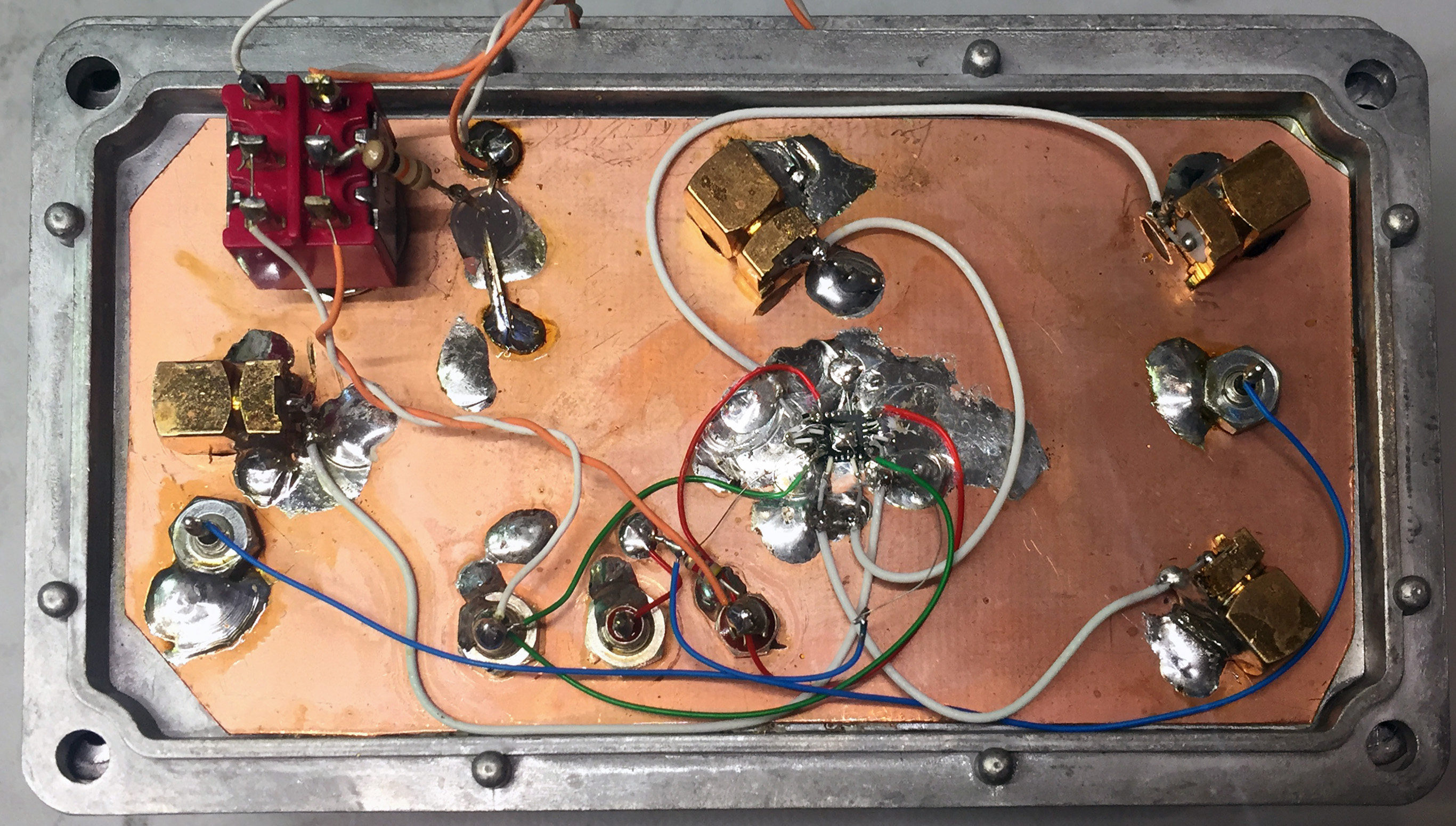
High value surface mount resistors can also be used as terminals and to anchor other parts.
The photograph below shows an example where I used the leaded multilayer ceramic decoupling capacitors to anchor DIP sockets. The RF bridge detector using 1N270 germanium diodes worked to 100s of MHz.
-
#36 Reply
Posted by
KE5FX
on 13 Aug, 2020 01:53
-
If you try that with modern current-feedback amps, you'll end up with a competitive entry in the "Who can build the highest-frequency oscillator on a breadboard?" thread. They will complain because you didn't actually use a solderless breadboard, but the spirit of the rules will certainly have been satisfied.
But hey, knock yourself out.
-
-
I was thinking that for the places in the circuit where multiple connections come together, I would use my rotary tool and cut an island in the coper board
That is a common method; I still prefer to glue or solder a little pad down if I am not wiring things in the air. Strips of copper clad board can be used as controlled impedance transmission lines.
High value surface mount resistors can also be used as terminals and to anchor other parts.
The photograph below shows an example where I used the leaded multilayer ceramic decoupling capacitors to anchor DIP sockets. The RF bridge detector using 1N270 germanium diodes worked to 100s of MHz.
Artwork, love it - Soldering the battery in is very hardcore!
-
#38 Reply
Posted by
uofmrob
on 14 Aug, 2020 13:18
-
I have another question for all of you experts. I've been thinking about this circuit design and I think it might not actually work for what I need. At the coil, I need about a watt of power, but will I actually get no power carrying forward in this circuit? Sure, I'll get a voltage carrying forward from the op amps, but will I get no significant current because of how the op amps work?
-
#39 Reply
Posted by
uofmrob
on 14 Aug, 2020 13:21
-
With the ferrite-based circulators in our instruments, they carry forward the 200 mW microwaves in our continuous wave instruments and even the 1000 W microwaves in the pulse instruments.
-
#40 Reply
Posted by
uofmrob
on 14 Aug, 2020 16:22
-
Thanks for the explanation!
-
#41 Reply
Posted by
KE5FX
on 14 Aug, 2020 16:22
-
I have another question for all of you experts. I've been thinking about this circuit design and I think it might not actually work for what I need. At the coil, I need about a watt of power, but will I actually get no power carrying forward in this circuit? Sure, I'll get a voltage carrying forward from the op amps, but will I get no significant current because of how the op amps work?
In combination with the available supply voltage, the power output is determined by the sum of the output impedance of the opamps, typically a few ohms, plus whatever series resistance is added at their outputs. The output current capability of the opamps is closely related to their output impedance; often the data sheet will show both.
The circuit as published uses opamps rated for output currents up to 70 mA, so that's about a quarter-watt into 50 ohms. Power in the 1-watt range is achievable, but you'll need to go with beefier opamps. The
THS3491 would be a great choice since it can run from +/- 12V rails. At lower voltages you'd need to scale down the series termination resistors at the outputs, and you're better off not doing that for various reasons (notably the ability to tolerate a reasonable amount of load capacitance and compatibility with 50-ohm cabling and components).
-
#42 Reply
Posted by
uofmrob
on 14 Aug, 2020 16:27
-
It looks like the ones that I ordered have an output current up to 100 mA. Then I think I should be OK. 1 W would be great, but even a quarter watt should be enough to see something if I can get a well-matched saddle coil with a high Q. Thanks again!
-
#43 Reply
Posted by
David Hess
on 14 Aug, 2020 16:31
-
I have another question for all of you experts. I've been thinking about this circuit design and I think it might not actually work for what I need. At the coil, I need about a watt of power, but will I actually get no power carrying forward in this circuit? Sure, I'll get a voltage carrying forward from the op amps, but will I get no significant current because of how the op amps work?
Power levels are limited by the output voltage and current capability of the operational amplifiers. Source termination further lowers the output power capability.
I think practical designs with integrated parts are going to be limited to less than 100 milliwatts. 36 volt and 200 milliamp parts can do a little better than this.
-
#44 Reply
Posted by
uofmrob
on 14 Aug, 2020 16:43
-
Thanks for the advice! I think that I'll try out the design and the ugly construction techniques that you all suggested this weekend with the ones that I ordered from Mouser and see if I can just get one that works at all and then look into more powerful op-amps for a second version if I can get this one to work.
-
#45 Reply
Posted by
uofmrob
on 14 Aug, 2020 17:03
-
-
#46 Reply
Posted by
uofmrob
on 14 Aug, 2020 17:16
-
-
#47 Reply
Posted by
uofmrob
on 15 Aug, 2020 19:12
-
Well, I learned another lesson. Buy more components than you need. 🤣. I snapped a pin off of one of the op amps, and clipped another one getting it out of the package. Those buggers are tiny! I've got another order in, but for now two of them are wired up with the filter capacitors holding them up and they are wired for power!
-
#48 Reply
Posted by
KE5FX
on 15 Aug, 2020 22:11
-
A good start!

And yes, never order just one or two of anything.
-
#49 Reply
Posted by
uofmrob
on 21 Aug, 2020 01:21
-
Hi everyone. I have it a whirl again tonight. The small surface mount op amps that I got are just too small. Well I can deal with the size, but the leads are just too fragile. Once you bend them once, any further flexing causes then to snap. I got them all wired up to power, but when I started soldering the resistors on, the leads kept snapping. This is what I have:
https://www.mouser.com/ProductDetail/Analog-Devices-Linear-Technology/LT1395CS5TRMPBF?qs=ytflclh7QUWCZinjfMpnVQ%3D%3DCan anyone recommend a part number for a good op amp for this application that would come in a DIP IC that would be easier to work with?
Thanks!
-
#50 Reply
Posted by
uofmrob
on 21 Aug, 2020 01:22
-
And maybe one that could give me the half watt output that I would need.
-
-
-
#52 Reply
Posted by
uofmrob
on 21 Aug, 2020 01:57
-
-
#53 Reply
Posted by
uofmrob
on 23 Aug, 2020 00:19
-
Hey everyone, that's for all the advice! I have a working circulator! There's no leakage at all. It passes reflections on with the exact signal voltage and if you put a 50 Ohm terminator in, everything down wind sees nothing. Thanks so much for all the help! Now in to designing a coil!
-
#54 Reply
Posted by
KE5FX
on 23 Aug, 2020 01:45
-
Awesome, good going! That's a perfectly reasonable way to do it as long as the IC adapter doesn't add a lot of stray capacitance.
-
#55 Reply
Posted by
uofmrob
on 23 Aug, 2020 01:53
-
I was having so much trouble with the fragility of the surface mount leads, I just decided to give this a whirl to see if it worked. This quad op amp is pretty low power on the specs (it's one that I had bought initially as a spec replacement for the one in the original paper). I'll probably have to swap out the IC for something that can put out more power, but I'll give this a shot first. At least I know I can get one to work!
-
#56 Reply
Posted by
uofmrob
on 24 Aug, 2020 01:18
-
One more question. Is there a reason that it wouldn't be safe to test this out with an oscilloscope in 1 MOhm mode? I was looking at the signal and my scope is acting funny now (it's a Tektronix 2430 scope). Did I bork my scope?

-
#57 Reply
Posted by
uofmrob
on 24 Aug, 2020 02:16
-
I checked and there are no shorts to ground or anything. It wouldn't be too surprising that my scope is dying just from being 30 some years old. But I certainly don't want to be doing something I shouldn't. I had a 20 MHz 2 Vpp sine wave on my function generator on port 1 and had a BNC cable running from port 3 to the scope and I was testing the effect of a 50 Ohm load on port 2. It works perfectly. Without the load on port 2, the signal gets reflected to port 3, but when you put the load in, the signal goes away completely.
-
#58 Reply
Posted by
uofmrob
on 24 Aug, 2020 03:48
-
The only thing I can think of is that I was counting on the source providing the ground. I had forgotten that and there was a point that I didn't have the source plugged in, but the scope was still connected. Without the ground from the source, there is a couple hundred millivolts between the ground plane of the circulator and the ground of the scope. That might have been the classic blowing up there scope through a current through the ground. Ugh, I should have grounded the circuit.
-
#59 Reply
Posted by
KE5FX
on 24 Aug, 2020 03:49
-
Vanishingly unlikely that you damaged the scope with this circuit. What is the scope actually doing?
If you take it apart for troubleshooting, remember to use a fan on the heat sinks. Failure to do that will hose a 2430.
-
#60 Reply
Posted by
uofmrob
on 24 Aug, 2020 03:55
-
It already had an issue with the relay on the 500mV/1V division on channel 2 not triggering on the high voltage side. Now it's not able to get a consistent trigger on any signal on either channel. You can see the signal, but it's completely unstable in the time domain.
-
#61 Reply
Posted by
uofmrob
on 24 Aug, 2020 04:13
-
I thought it was maybe the function generator putting out an unstable signal (it's a FeelElec FY6900 60 MHz AWG), but my analog scope locks onto its signal up to its bandwidth limit just fine.
-
#62 Reply
Posted by
uofmrob
on 14 Sep, 2020 20:43
-
Hi everyone,
I realized that I forgot to send a final thank you to everyone for all the help. I got it working perfectly!
Rob
-
#63 Reply
Posted by
uofmrob
on 14 Sep, 2020 20:45
-
Also, the scope is OK. My 4-year-old had messed with the knobs while I wasn't looking and had changed the horizontal scaling so much that it was seeming to have a signal that it couldn't lock on, but it was interpolating and when I went back to a proper scaling, it triggered fine.
-
-
Also, the scope is OK. My 4-year-old had messed with the knobs while I wasn't looking and had changed the horizontal scaling so much that it was seeming to have a signal that it couldn't lock on, but it was interpolating and when I went back to a proper scaling, it triggered fine.
One of the unexpected dangers of having children!