I've been following this thread.. excellent work!
I want one:)
Great project. Is there a chance to public full schematic, software and firmware?
as I already have sample of ad5933 for some years, I want one too !

as I already have sample of ad5933 for some years, I want one too !
He is using the Analog Discovery for hardware, not the ad5933.
AcHmed99 is correct I have switched to using an Analog Discovery unit (14 bits vs 12 bits, 100 Msps vs 1 Msps etc) plus you get do do your own DFT (reference against DUT) with the Analog unit.
Sure it's 10x the cost (~$220) of a single AD5933 (~$25), but IMO well worth the extra money.
Currently I'm working on an amplifier allowing me to measure down to near 1m?, as the current minimum of ~13m? just isn't low enough in many cases. I've got some AD8038 on order that will hopefully allow this with the full 10+MHz bandwidth and some gain.
With the aim of 1m? to ~500k? within 1Hz to 10MHz, I might have to compromise a bit on accuracy in the extremes, but it should be possible.
Nicely done.
Thanks, encouragement is a good motivator

Your posts have been very informative! I have to agree that the Analog Discovery appears well worth the money.
I remember the excellent thread in 2013 by The Electrician about capacitor measurements on an Impedance Analyzer and thinking to myself how really useful a device like this would be on the bench.
Little did I know at the time that I would later be witnessing a capable Analog Discovery/Impedance Analyzer blossom into reality. This is a fascinating thread indeed.

I've discovered that too long (200mm) measurement wires do introduce a relatively "large" amount of inductance (250nH+) and does have some effect on e.g. the resonance frequency when measuring caps and inductors. I can only estimate the error but measuring a 100nF capacitor should probably resonate around 5-7MHz but I only measure half that, of course dependent on the capacitor, and not a common published spec, so a bit of guesswork. Anyway, I find very short Kelvin connections (~30mm) give significantly better results at higher frequencies.
I'm thinking about methods to compensate for longer leads as really short leads are more difficult to work with, I'd like to be able to stick probes in a PCB and measure impedance where interesting, decoupling etc.
Here a test of a somewhat common (I guess) 10uF, 100nF, 10nF ceramic capacitor combination, picture of the setup:

Apologies for messy soldering, did it on the table with a 3.5mm tip I had in the iron already, really need more than 2 hands to hold tweezers and iron when doing this. (so many excuses)
Measured at the point of the 10nF capacitor:

And measured at the point of the 10uF capacitor:

Interesting difference, just moving the probes a few mm, anyway, still got some ~30-50nH and ~20pF error. And results above 10 MHz are questionable, plus currently unable to measure below 13mR, so some error on the low.
Less fortunate combination of 1000uF electrolytic with 220nF film in parallel:

I remember the excellent thread in 2013 by The Electrician about capacitor measurements on an Impedance Analyzer and thinking to myself how really useful a device like this would be on the bench.
Little did I know at the time that I would later be witnessing a capable Analog Discovery/Impedance Analyzer blossom into reality. This is a fascinating thread indeed.
Yeah, the many measurements by The Electrician with his precision Hioki analyzer and explanations have been a great inspiration.
Of course this solution will not provide anywhere near the same level of precision, but still very useful.
Jaxbird, the old HP/Agilent/Keysight fixtures for impedance analyzers are available on eBay:
http://www.ebay.com/itm/HP-Agilent-16047A-/400834797655?pt=LH_DefaultDomain_0&hash=item5d539da057
http://www.ebay.com/itm/HP-Agilent-16034E-LCR-Meter-surface-mount-Test-Fixture-with-case-HP-4274A-4275A-/141416235256?pt=LH_DefaultDomain_0&hash=item20ed1080f8
They are somewhat pricey, but I've noticed that there are Chinese look-alikes available for much less:
http://www.ebay.com/itm/TH26001A-4-terminal-test-fixture-for-LCR-meter-TH2811D-/261419837445?pt=LH_DefaultDomain_0&hash=item3cddd62805
There is a surface mount version that shows up occasionally on eBay, too.
The spacing of the BNC connectors on other-than-Agilent impedance analyzers, such as Wayne-Kerr, Hioki, Tonghui, etc., is the same as the Agilent, so all these various fixtures will fit all the various impedance analyzers (there may be the occasional exception).
I'm sure you would get better results at the higher frequencies if you would install your project in a metal box with 4 BNCs that would accept a fixture on the outside of the box.
Thanks, it would be absolutely nice to have some proper test fixtures for both leaded and SMD
, but I think they might be a bit overkill for this project, I'm not convinced that the somewhat questionable precision I will be able to achieve would justify the nice fixtures. But might change if I find a reliable way to compensate for the added inductance and capacitance in software .. still thinking about that one. I think I will have to read some more of this document :
http://cp.literature.agilent.com/litweb/pdf/5950-3000.pdfit's been very helpful so far on a lot of practical considerations and the basic complex number math for many of the calculations.
But before that I'll attempt to build an amplifier circuit that will allow measurements down to near 1mR with full (10+MHz) bandwidth with minimal phase change.
Since it's weekend, I've been working on a reliable way to calibrate the little instrument.
The Agilent Impedance Measurement Handbook has been a great help. (thanks Agilent, or rather Keysight).
It does describe in some detail the method used to perform an Open/Closed calibration to compensate for parasitic inductance etc.

There is a bit more to it, but that formula is a good start.
Example of difference in measurement of a 1uF capacitor, with and without calibration:
Without calibration:

With calibration:

Quite a difference in the resonance frequency.
Did a quick accuracy test following the open/short calibration. This calibration doesn't require any references, it simply requires a scan with disconnected Kelvin clips followed by a scan with shorted clips.
Anyway, using a few resistors from 10k to 10mR, mostly standard 1% and 5%, but very low values (10mR and 20mR) are just short pieces of wire made using a conventional milliohm/microohm meter.
All measured at 1kHz using 50R shunt:
| Nominal value: | Measured value: |
| 10k | 9.466k |
| 1k | 0.987k |
| 100R | 98.8R |
| 10R | 9.95R |
| 1R | 0.986R |
| 100mR | 98.7mR |
| 50mR | 50.8mR |
| 20mR | 19.8mR |
| 10mR | 10.5mR |
At 10k and 10mR is pushing it a bit, but besides that it's pretty good accuracy within a few %.
It will easily do higher than 10k, with e.g. a 5k shunt. Input impedance should be in the mega ohm range, so good accuracy should be possible up to a few 100k. Will test that at some point.
Picture of test resistors for reference:

While I have figured out how to perform and apply calibration, I am still fumbling with a simple problem.
The problem is, when applying calibration, I need to use complex numbers, meaning I build tables of these, indexed by frequency.
But as the measurement frequency is likely to be between 2 frequencies in the lookup table, interpolation is needed.
Is there an easy standard way to interpolate between 2 complex numbers? (just linear interpolation, no fancy spline needed)
Must be a somewhat common problem, but quick google just seem to suggest everyone use matcad

I'm sure there is a simple way of doing it, and I'll figure it out eventually, but any hints much appreciated.
Regarding to doing the accuracy measurements at 1kHz, why not higher with 10MHz bandwidth available? Well, it's simply to avoid any errors introduced by the resistors.
Nicely explained by these charts: (again credits go to Agilent)
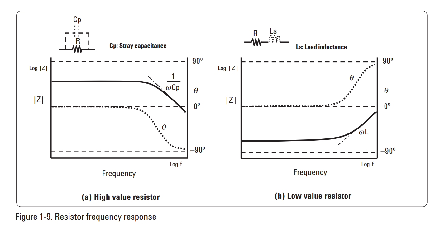
Here demonstrated with real measurements: (the 10k resistor is a bit too low in value to show much stray capacitance, but trend visible at 10MHz)

Using 100mR it's much easier to see the effect of lead inductance:


