-
Yes, 2Mhz crystal is the closest cheap standard crystal.
500Khz resonators are also a standard, I believe they are used for 3.5inch floppy drive motor driver oscillator clock (the orange rectangle visible and accessable on the bottom of the drive next to the motor wheel), but, the tolerance is 2khz though tunable with your varicap.
Just for reference if you are doing an existing order and looking to test, cheap stock here:
https://www.digikey.com/products/en/crystals-oscillators-resonators/resonators/174?k=resonator&k=&pkeyword=resonator&pv1989=0&pv69=80&FV=fff4000d%2Cfff80397%2Cffe000ae%2C22c00f2&mnonly=0&newproducts=0&ColumnSort=0&page=1&quantity=0&ptm=0&fid=0&pageSize=500
and here:
http://www.mouser.com/ProductDetail/ECS/ZTB500E/?qs=oGPfoFmS6kS1ad5kgPbJGw%3d%3d&utm_source=findchips&utm_medium=aggregator&utm_campaign=ZTB500E&utm_term=ZTB500E&utm_content=ECS
-
Surprised you've done that much routing before finishing placement to see how much things can be pushed together to reduce overall size (I'm assuming there's quite a bit more to fit onto that layout). Seems to be quite a lot of unused space near the BNCs that the bottom-left corner stuff could be pushed into.
As mentioned earlier,people may want to display it, so there should be room to lay the regulators and tall caps flat to allow a sensible distance to a clear cover.
You certainly also want a few more mounting hole locations for a PCB that size, and some near the BNCs for support in case the panel-mount isn't used.
So I went ahead and pushed the Z-Axis amplifier and part of the multiplexer logic in about 20mm towards the left. I had to get a little craeative with routing, but it works. I also finished the sound section (ignore the placement of the three monostable timers, I plan on moving and rotating them some once I get other sections in, what's shown is where I just where I just happened to stick them before calling it a night).
I also added additional mounting holes and added equivalent circuit silkscreen to the Multiplexer Logic section (as to test to see if I could break it up and still make it understandable).
Now that I've got the existing elements tidied up and I'm happy with how things are coming, it's back to full bore on getting the final three sections completed.
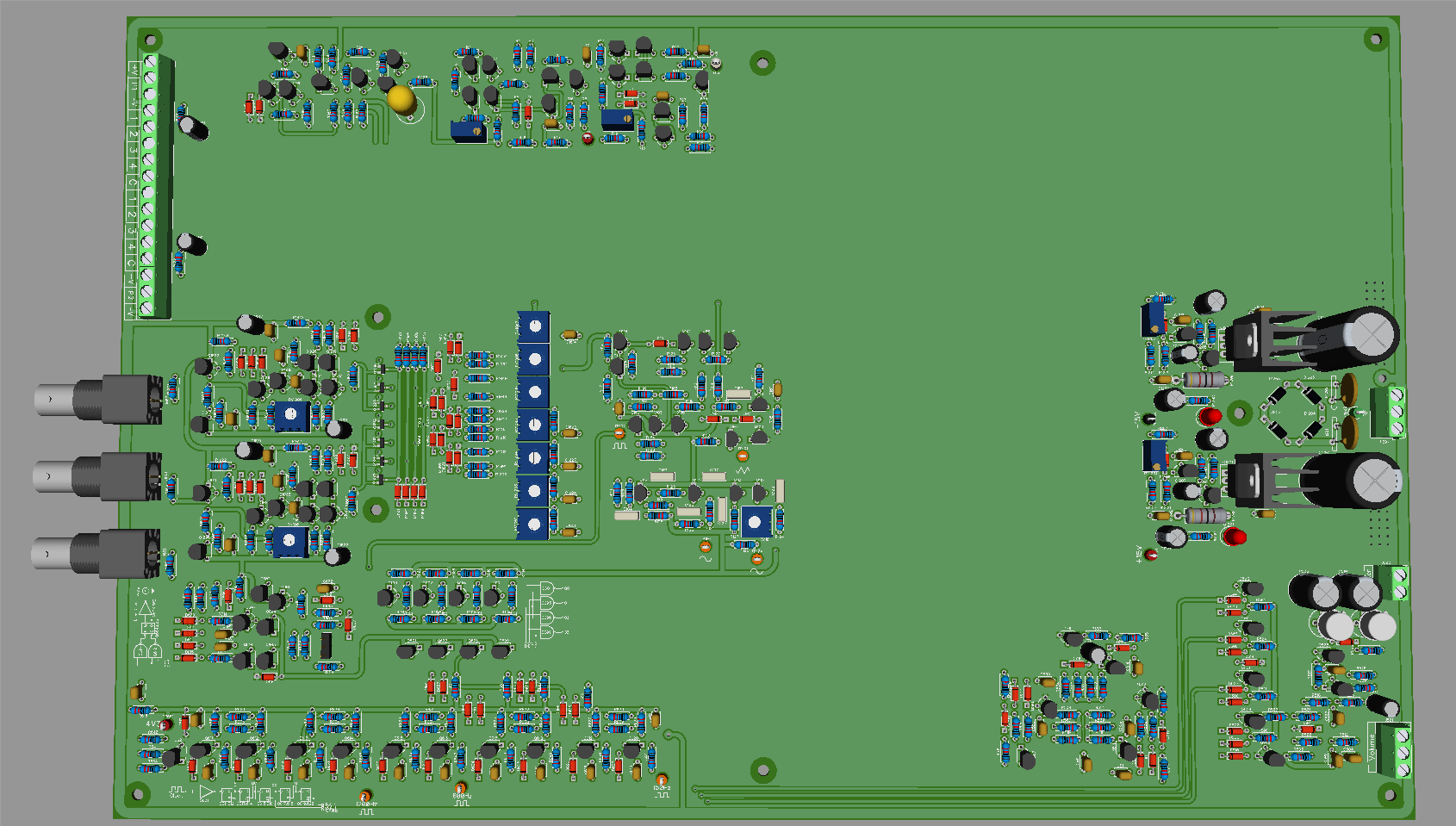
http://timb.us/Projects/Scope_Pong/Layout_20170414.pdf -
The only time accuracy may be an issue is if you're doing colour, for the subcarrier, but that would probably be a seperate xtal anyway. The tolerance on a 500K resonator should be more than enough, and should be a lot more stable than an LC osc.Using a discrete crystal or resonator in place of the coil for your master oscillator still keeps your circuit a valid all discrete design.
It will also prevent users from accidentally destroying their TV h-sync yoke driving transistor on their TVs if the inductor driven oscillator doesn't drift the H-sync by 1/4 of a KHz. Modern digital sampling screen's ADC use tightly locked crystal PLLs, they wont be as forgiving with out of spec HSync speed compared to an all analog CRT like the Commodore 1084s monitor you are using.
The master oscillator with the current crappy inductor is already stable enough for any analogue TV or monitor and will be amply so with a better inductor. I can't immediately see how any TV could burn out its yoke due to sync frequency drift. In the absence of a video signal the raster scan oscillators are without any signal to lock onto at all and are are free to rail out or drift around within their operating frequency limits. Back in the day hobby circuits published in electronic mags for producing video displays often used a pair or 555 timers injection-locked to each other to provide the H and V sync! I have two such "vintage" articles sitting on my desk right now and I can't recall ever reading a warning to monitor your TV for smoke in addition to a stable image whilst tweaking those 555 frequency-setting trimpots!
Resonators typically have crappy tolerances and limited scope for frequency tuning and I'm not sure if they're readily available in 500 kHz. I'm going to buy one of those composite video to HDMI converters to asses how sensitive it is to the field and frame frequency stability/accuracy. Until it is proven that the basic LC oscillator is inadequate it stays. If it does prove to be inadequate or marginal I will substitute the LC oscillator with a 2MHz crystal oscillator followed by an additional pair of toggle-flip-flops to divide down to 500 kHz - 2 MHz is the nearest readily available crystal frequency, making that the only real highter-stability master oscillator option.
-
There were some computer monitors that would blow the horizontal output transistor or other parts if they were fed an incompatible sync signal, but most would tolerate it at least for a while. I suppose there may be a few TV sets out there that would lock onto a wildly out of spec horizontal sync and blow up but it's not something I've ever had happen. Certainly a few percent off is not going to hurt, I've even fed PAL-50 to standard NTSC CRT TVs before and most will display it to a usable degree without dying.
-
The H-sync difference between PAL and NTSC is 15.625 vs 15.734k, only a difference of 0.109khz. CRTs wont even feel the difference. Even your analog VRC's playback jitters it's H time timing within this range. Though, the H yoke drive in CRT is fairly strong with a tight PLL lock since after drawing a slow line, it needs to fly back from right to left really fast and going too far out may have consequences.
As for the vertical, 50hz to 60hz, the vertical's return speed after drawing a frame is a much slower action and this guy, you may easily stretch from 45hz to 65 or even 70hz without frying anything, or, the slow VS PLL in the monitor just wont lock and you will see that scrolling bar.
With the worst possible +/- 2khz error on the 500khz resonator I listed, GK's H sync generator would be from 15.562-15.625-15.6875Khz. The error doesn't even make it to NTSC's 15.734k. For B&W, the listed resonator is a safe cheap 0.7$ reference which wont destroy any monitors at all and would probably drop into his current circuit with ease. He could even cheapen it up with a 2 transistor oscillator instead of the current 6 if he likes. Just accidentally touching a point with your finger on the inductor tuned oscillator will go way further out of bounds. -
I put the soldering iron away this afternoon and made a start at documenting this discrete-transistor Pong MkII. This is mostly because the circuits were part scribbled on multiple sheets of paper and part in my head. By alternating between soldering and documenting the design I have less chance of getting lost.
Here are complete details of the horizontal timing and video generator board. A master LC oscillator of 500 kHz clocks a 5-bit binary ripple counter made up of cascaded toggle flip-flops.
The necessary video signals are simply decoded by (N)AND gates. Some trickery was required here however as this method of decoding a ripple counter is prone to glitches in the decoded outputs as the clock state ripples through the binary counter due to the propagation delays of the flip-flops. Glitches on the decoded outputs are not acceptable here as the video signals are being generated live as each horizontal line is being scribed on the display screen.
I solved this problem by designing the flip-flops of the ripple counter to be quite fast (using MPSH10 transistors) and conversely designing and (N)AND gates for decoding to be only adequately fast for the application, rather than excessively so, such that the decoders are too slow, by a comfortable margin, to respond to and pass through the erroneous binary states of the counter during the ripple-through of the clock.
The DTL (diode-transistor-logic) N(AND) gates are made "slow" by using comparatively-lowly BC550C transistors with a relatively weak base pull-up. The AND gates that provide the horizontal video signals for generating the scoreboard display digit segments are comprised of a BC550C NAND followed by an MPSH10 DTL inverter. The through-put propagation delay of this combo is a clean and stable ~120nS and the MPSH10 inverter provides (in addition to the required polarity inversion) a squared-up output with fast rise and fall times.
The MSB (HR16) of the horizontal ripple counter is at the line frequency (15,625 kHz) and it is used as the clock source for the vertical line counter. The horizontal video component of the paddles and the court net are approximately 600nS wide and 300nS wide respectively. As this is substantially less than the 2uS master clock period, these video signals are produced by triggering high-speed monostables.
All of the signal outputs of the horizontal timing unit are digital, bar "H_SCAN", an analogue line-scan ramp signal. H_SCAN is provided for the Ball Horizontal Movement circuit.
The board itself. I currently have a rather crappy ferrite-cored "choke" with a rather poo temperature coefficient soldered into the tank circuit of the master oscillator, as this is what immediately at hand. I'll will be sourcing a better core material to wind a better substitute.
Damn, you've been busy GK! I have a feeling I won't be able to fit this project all on a single large board... It looks like it's going to be *a lot* of parts!
(Though laying out a PCB for this project should be *a lot* faster as my library is already mostly setup and I've learned a lot so far doing the Scope Pong board.)
Speaking of which, I'm hoping to have the first revision of Scope Pong done by week's end. -
There were some computer monitors that would blow the horizontal output transistor or other parts if they were fed an incompatible sync signal, but most would tolerate it at least for a while.
They must be rare examples of crap/cheap design.
-
With the worst possible +/- 2khz error on the 500khz resonator I listed, GK's H sync generator would be from 15.562-15.625-15.6875Khz. The error doesn't even make it to NTSC's 15.734k. For B&W, the listed resonator is a safe cheap 0.7$ reference which wont destroy any monitors at all and would probably drop into his current circuit with ease. He could even cheapen it up with a 2 transistor oscillator instead of the current 6 if he likes. Just accidentally touching a point with your finger on the inductor tuned oscillator will go way further out of bounds.
I didn't claim that an equivalent resonator oscillator would be less stable or accurate than an LC one. Re the design involving those 6 transistors - the LC oscillator requires a frequency trim and you can't get 1nF trimmer capacitors. I biggest I could get at the local Jaycar last week afternoon was 8.5-100pF. I put that in parallel with 150pF and that still gives me adequate range to trim for the inductor tolerance. To get down to 500 kHz with ~205 pF a 470uH inductor is required. This is a poor LC ratio for a typical basic oscillator design as the inductance is large and the capacitance is small. For these values XL=XC=~1500 ohms at 500 kHz, so in an idea case restive loading of the tank circuit must be ~15k for an tank circuit Q of just ten, but in reality higher as the resonate Q is lowered further from the ideal, in this case primarily by the inductors non-zero series resistance.
The Darlington-connected input transistors present a high impedance load to the tank circuit maintaing Q. The high input impedance also helps preserve Q by permitting positive feedback to be lightly coupled (via 47k) to the tank circuit with minimal loop-gain attenuation. The Darlington transistor pair connected in a long-tail pair double operates as a limiting amplifier, giving a squared-up and stable amplitude of oscillation, further aiding stability. The first high-speed toggle flip-flop of the horizontal ripple counter requires a clock source of adequate amplitude and rise/fall dv/dt. This is provided by the second long-tail-pair limiting amplifier, bringing the total transistor count to six.
The whole purpose of this design exercise is to construct and demonstrate something more impressive than a LED-blinkie with rudimentary components. For a high frequency clock source they don't get much more rudimentary than a trimcap and a non-specialized, non-custom inductor.
-
Not to distract you, but I used to have a few Pong game boards from some company, and one worked. I tried to fix the other ones, and started reverse-engineering it. It had lots of 4066 (or 4016's) analog switches. One switch must have been bad because the ball would launch from one side and slowly get lower and lower as it went back and forth. Never did fix it... life went on. Great project there, very retro. Needs to go into an old Apple-II case!
-
Would an RC osc be significantly less stable ? Maybe a phase-shift osc?With the worst possible +/- 2khz error on the 500khz resonator I listed, GK's H sync generator would be from 15.562-15.625-15.6875Khz. The error doesn't even make it to NTSC's 15.734k. For B&W, the listed resonator is a safe cheap 0.7$ reference which wont destroy any monitors at all and would probably drop into his current circuit with ease. He could even cheapen it up with a 2 transistor oscillator instead of the current 6 if he likes. Just accidentally touching a point with your finger on the inductor tuned oscillator will go way further out of bounds.
I didn't claim that an equivalent resonator oscillator would be less stable or accurate than an LC one. Re the design involving those 6 transistors - the LC oscillator requires a frequency trim and you can't get 1nF trimmer capacitors. I biggest I could get at the local Jaycar last week afternoon was 8.5-100pF. I put that in parallel with 150pF and that still gives me adequate range to trim for the inductor tolerance. To get down to 500 kHz with ~205 pF a 470uH inductor is required. This is a poor LC ratio for a typical basic oscillator design as the inductance is large and the capacitance is small. For these values XL=XC=~1500 ohms at 500 kHz, so in an idea case restive loading of the tank circuit must be ~15k for an tank circuit Q of just ten, but in reality higher as the resonate Q is lowered further from the ideal, in this case primarily by the inductors non-zero series resistance.
The Darlington-connected input transistors present a high impedance load to the tank circuit maintaing Q. The high input impedance also helps preserve Q by permitting positive feedback to be lightly coupled (via 47k) to the tank circuit with minimal loop-gain attenuation. The Darlington transistor pair connected in a long-tail pair double operates as a limiting amplifier, giving a squared-up and stable amplitude of oscillation, further aiding stability. The first high-speed toggle flip-flop of the horizontal ripple counter requires a clock source of adequate amplitude and rise/fall dv/dt. This is provided by the second long-tail-pair limiting amplifier, bringing the total transistor count to six.
The whole purpose of this design exercise is to construct and demonstrate something more impressive than a LED-blinkie with rudimentary components. For a high frequency clock source they don't get much more rudimentary than a trimcap and a non-specialized, non-custom inductor.
The trimmer value issue shouldn't be a major problem as you can shunt it with fixed caps to get within the required trim range. -
Would an RC osc be significantly less stable ? Maybe a phase-shift osc?
The trimmer value issue shouldn't be a major problem as you can shunt it with fixed caps to get within the required trim range.
An RC relaxation or phase-shift oscillator oscillator would be a lot less stable. You won't find them in preference to LC oscillators in your AM radio.
I think you misunderstand about the trimmer capacitor value; if the inductor tolerance is +/- 20% and the biggest practical trimmer you can get is ~100pF then you simply can't bung a couple of nF in parallel to get an adequate, high-Q L-C ratio at 500 kHz because you then won't have enough trim range - unless you plan to S.O.T maybe multiple padding capacitors. -
Okay, made some very satisfying progress this evening. I got half of the scoreboard video segment decoder array soldered up onto the half-a-board of empty space remaining on the Vertical Timing board. This means that I can now generate a video display with player 1's score counter digits displaying on the scoreboard.
One thing that I was aware of and initially resigned to just living with is that because of inevitable and non-zero propagation delays through my horizontal ripple counter, the decoder circuitry and gate array, is that the generated digit segments would not all align 100% perfectly. Exactly how much of a visual impact this would have wasn't of course tested until now.
The first picture attached below shows the initial result. Well, not too bad at all and I guess a perfectly acceptable degree of quality for a display generated entirely with discrete transistors and diodes, right?
Well I stared at the screen for about 30 seconds and decided NO!. I suddenly remembered that I still had stashed under my bench the prototype discrete-transistor (again MPSH10) master-slave, pure-edge-triggered delay flip-flop (DFF) that I built as an evaluation piece for my 16-bit processor project. I described this DFF previously in reply #12 here: https://www.eevblog.com/forum/projects/homebrew-digital-computer-system/msg460596/#msg460596
So, I switched off power and pulled the scoreboard video logic signal wire from the breadboard and wired it to the D-input of my DFF instead. I modified my clock oscillator buffer to provide complementary (out of phase) clock signals. One for the horizontal timing circuit ripple counter and the other exclusively for the clock input of my DFF. So now I have a DFF clocked half a period (1uS) out of phase with my video generator circuitry. This 1uS is ample time for all of my horizontal counting flip-flops to ripple-through and the decoding to settle. The Q output of my DFF is now the scoreboard video signal, delayed by half a clock cycle, rather than sent to the screen live. The DFF effectively operates as a memory cell/buffer. This is data deskewing, boys and girls.
The second attached picture shows the result - perfectly aligned digit segments. Yoo hoo! This project is slowly evolving into one of the more satisfying things I've built in a while. The third attached picture shows the complete set up as it currently sits. The circuitry on the bread board is just a couple of discrete N(AND) gates, a resistor matrix and a 75-ohm-zout emitter-follower buffer to combine the discrete logic-level video, blanking and sync signals into the one composite video signal.
As it currently stands, there are 107 individual transistors gating electrons. Considering what has been achieved so far for a video image, I don't think that is too bad at all
-
Damn, you've been busy GK! I have a feeling I won't be able to fit this project all on a single large board... It looks like it's going to be *a lot* of parts!
(Though laying out a PCB for this project should be *a lot* faster as my library is already mostly setup and I've learned a lot so far doing the Scope Pong board.)
Speaking of which, I'm hoping to have the first revision of Scope Pong done by week's end.
Yeah, I think you'd have difficulty fitting it onto single board of practical size. This would be a contender for all-SMD construction, I think. The MPSH10 transistors in any case have been obsoleted in the TO-92 case (I have a big stash just for me though ).
).
The transistor count so far isn't too bad though; I've got most of the logic completed and am still way short of the transistor count of the oscilloscope version - but the analog paddle generation and ball movement, sound and colour-video encoding circuits are going to reverse that situation before long.......
I am, admittedly, feeling a tad immodestly-full of myself this evening.....
Seriously now, am I just f%$@ing awesome or what?
-
I am, admittedly, feeling a tad immodestly-full of myself this evening.....
Seriously now, am I just f%$@ing awesome or what?
Hmmm, not sure. Maybe we need to take a poll or something. LOL!
-
Damn, you've been busy GK! I have a feeling I won't be able to fit this project all on a single large board
Vertical resistors & diodes ?
-
Damn, you've been busy GK! I have a feeling I won't be able to fit this project all on a single large board
Vertical resistors & diodes ?
Yeah, that's an option I suppose, but I've always hated kits that do that for some reason. It's a PITA to insert and solder plus it makes it a lot harder to probe. (I've also always felt vertical mount resistors and diodes are a lot easier to damage or something; though I have no proof if that's true or not.)
Anyway, since this would be a more advanced kit, I'm thinking SMD might be the way to go (since the higher end transistors are only available in SMD anyway it would make sense). I could use 1206 or larger parts, to make it fairly easy to hand solder.
Another thought is to break each section onto its own board and then have a backplane board with edge connectors and the power supply on it. That way everything would still be easily visible for display purposes and easy to access and service. Most Chinese board houses will do gold fingers for a couple of bucks, so it's doable. -
For hand soldering, 0805 isn't really any harder than 1206, though 1206 does allow for more tracks to be jumped over.
-
For hand soldering, 0805 isn't really any harder than 1206, though 1206 does allow for more tracks to be jumped over.
Yeah, that was my thought. Since it'll likely be two layers, being able to route under components is a big plus! -
Also on a home made board without a solder mask, with even 1 trace under an 0805 could potentially solder short without one knowing it. 1206 is the safer choice and you can keep relatively thick traces.
-
Also on a home made board without a solder mask, with even 1 trace under an 0805 could potentially solder short without one knowing it. 1206 is the safer choice and you can keep relatively thick traces.
True, but is anyone seriously going to bother homebrewing a PCB that complex when you can get proper PCBs so cheap?
And for a SMD board, there would be a lot of through-links, and allowing for homebrew would mean you couldn't put any vias under components. -
Seriously now, am I just f%$@ing awesome or what?
Ok.
Now you've done it...
Once this is completed,
I am expecting to see you do a multi-ball with an XY thrust style movable player avoidance game,
or,
a center stationary player aim and shooting multiple bouncing balls which will deflect them away as they also bounce off the screen boundaries only to eventually head back at you.
Either, or, sort of the building a part of something like an all transistor asteroids.
-
I've been thinking about a vector game such as asteroids in some form or another for a little bit now. I've already built the CRT X-Y display after all:
https://www.eevblog.com/forum/chat/show-me-some-cool-stuff-you've-made!/msg1127985/#msg1127985
-
Looking at your pong layout, I was thinking along the lines of a base unit, clock generators, sound generator, with a 16 channel xyz(RGB) analog switch network going to 16 edge card connectors. Each card connector will have the x,y,z(RGB) & all audio tone fx channel ena & cross x/y position of each channel for collision detectors + x1/y1 fire1, x2/y2 fire2, global reset, global start input on each board. Each board will basically be a programmable sprite, all identical, with a few jumpers to configure function.
Remember you wanted to make your ultimate +/-100v analog computer, instead, this would be your ultimate, configurable all transistor video game console.
You may also change the base unit for a raster interpreter version later on. I would still recommend 480p/720p RGB VGA, VGA to HDMI converters are only 10$ which include stereo audio line input in stereo so you can see and hear on any TV today, in progressive 60hz HDTV.
Kind of shocking that these games would work in the 1960s...
-
Also on a home made board without a solder mask, with even 1 trace under an 0805 could potentially solder short without one knowing it. 1206 is the safer choice and you can keep relatively thick traces.
True, but is anyone seriously going to bother homebrewing a PCB that complex when you can get proper PCBs so cheap?
And for a SMD board, there would be a lot of through-links, and allowing for homebrew would mean you couldn't put any vias under components.
That's my thought too. Going all SMD there would be so many vias I couldn't really see anyone ever etching one by hand, especially when you can order a PCB so cheap from China. -
An additional 9 transistors soldered in and the scoreboard readout is complete. The gate array for the scoreboard digital readout is just a 3-input DTL NAND gate for each segment, all with the open-collector outputs tied together and thus ORed.
For each NAND gate, one of the three inputs is fed the vertical video component for the respective segment whilst the second of the three inputs is fed the horizontal video component. The third input is the control line to switch the respective segment OFF. The inputs of the DTL NAND gates default high courtesy of the resistive pull-up, so all of the segments, with the control inputs left floating, default ON.
The decimal outputs of the player score counters will be active-low, open-collector-outputs, asserting the NAND gate control inputs via a simple diode array performing the decimal to seven-segment decode. Doing it this way (turning the segments OFF rather than ON) saves 24 diodes in the decoding array and is a natural fit to the operation of the DT-logic.
After dinner I'll solder up the last remaining circuit block of the Vertical Timing board in the remaining board space; this being the V_SCAN vertical ramp generator, which is identical to the horizontal one, just with a different time constant. The V_SCAN ramp is required for the Ball Vertical Movement circuit and also the Paddle movement circuits. I intend to build the paddle video generation and control/movement circuits tomorrow.