-
Both boards are looking great!
Tim, glad to hear your eye is OK. With a board that size, can the ground plane sink enough heat for the regulators?
GK, it was interesting reading about the collision detection challenges. Looks like it's running really well. -
Yes, the board looks excellent!

Will you be providing a quality .pdf before the GND pour for closer inspection?
-
Both boards are looking great!
Tim, glad to hear your eye is OK. With a board that size, can the ground plane sink enough heat for the regulators?
Yeah, it should be able to. The heatsinks I've chosen actually have solder pins, so heat will be transferred directly into the top and bottom copper pours, which should greatly increase their effectiveness. I've run some numbers and we should be good for a 15VAC to 18VAC input range with a constant 400mA output on both regulators.Yes, the board looks excellent!
Will you be providing a quality .pdf before the GND pour for closer inspection?
Of course! I'll post a 600DPI PDF of the layout for review before ordering the test boards.
-
Both boards are looking great!
Tim, glad to hear your eye is OK. With a board that size, can the ground plane sink enough heat for the regulators?
Yeah, it should be able to. The heatsinks I've chosen actually have solder pins, so heat will be transferred directly into the top and bottom copper pours, which should greatly increase their effectiveness. I've run some numbers and we should be good for a 15VAC to 18VAC input range with a constant 400mA output on both regulators.
Great. I was curious because of Mike's comment regarding putting this into a low-profile enclosure. I'm not sure if he envisioned going lower than the heatsinks in the 3D drawing, but plenty of dissipation is good. -
Your original hand drawn schematics didn't specify film
Whoops.
Okay, fixed!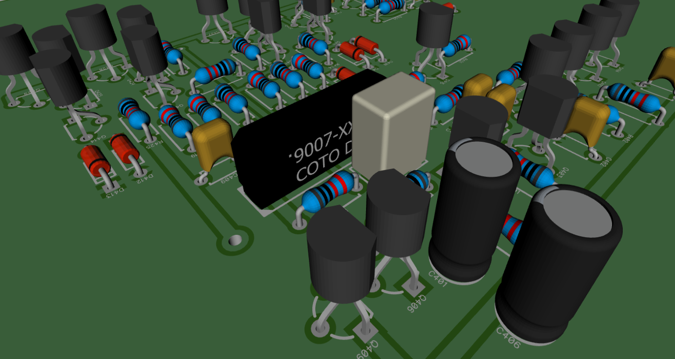
-
Both boards are looking great!
Tim, glad to hear your eye is OK. With a board that size, can the ground plane sink enough heat for the regulators?
Yeah, it should be able to. The heatsinks I've chosen actually have solder pins, so heat will be transferred directly into the top and bottom copper pours, which should greatly increase their effectiveness. I've run some numbers and we should be good for a 15VAC to 18VAC input range with a constant 400mA output on both regulators.
Great. I was curious because of Mike's comment regarding putting this into a low-profile enclosure. I'm not sure if he envisioned going lower than the heatsinks in the 3D drawing, but plenty of dissipation is good.
Right, I see now that he was asking about doing away with current vertical heatsinks and instead adding horizontal board mount ones, so the regulators could be folded over. I can't really do that as they take up a good deal more space, which I just don't have. If the user's case can't tolerate the height of the heatsinks (which are about 25mm tall) they could always mount the transistors externally to the case itself and simply run wires between them and the board. That would solve the problem, right?
That would work well with a metal case. (For a plastic or wood case they'd need to mount the transistors to a largish heatsink to dissipate the heat.)
Anyway, here's the provisions to fold the filtering caps over: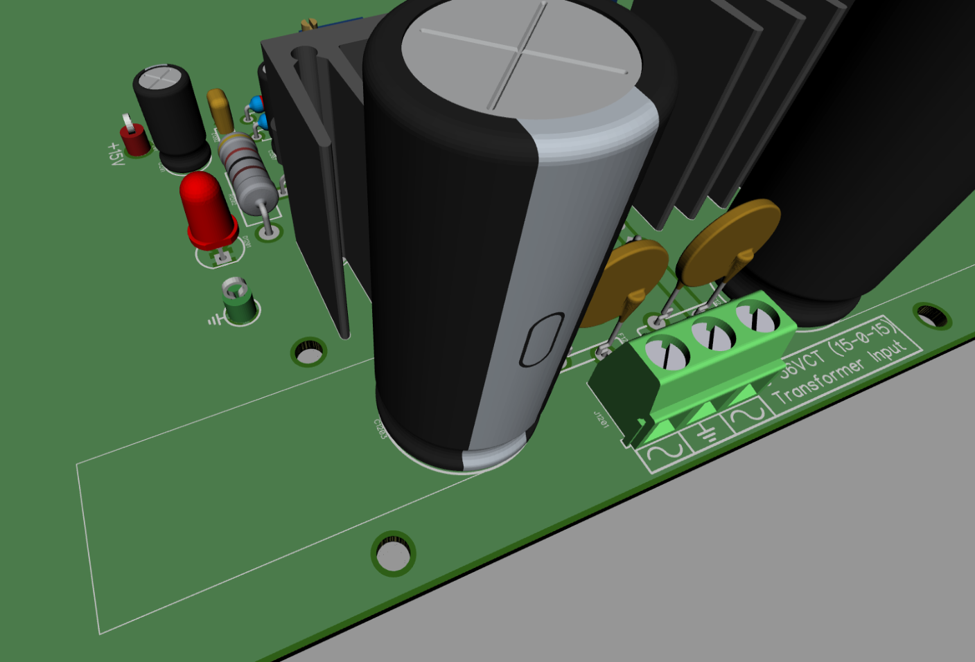
-
Another progress update:
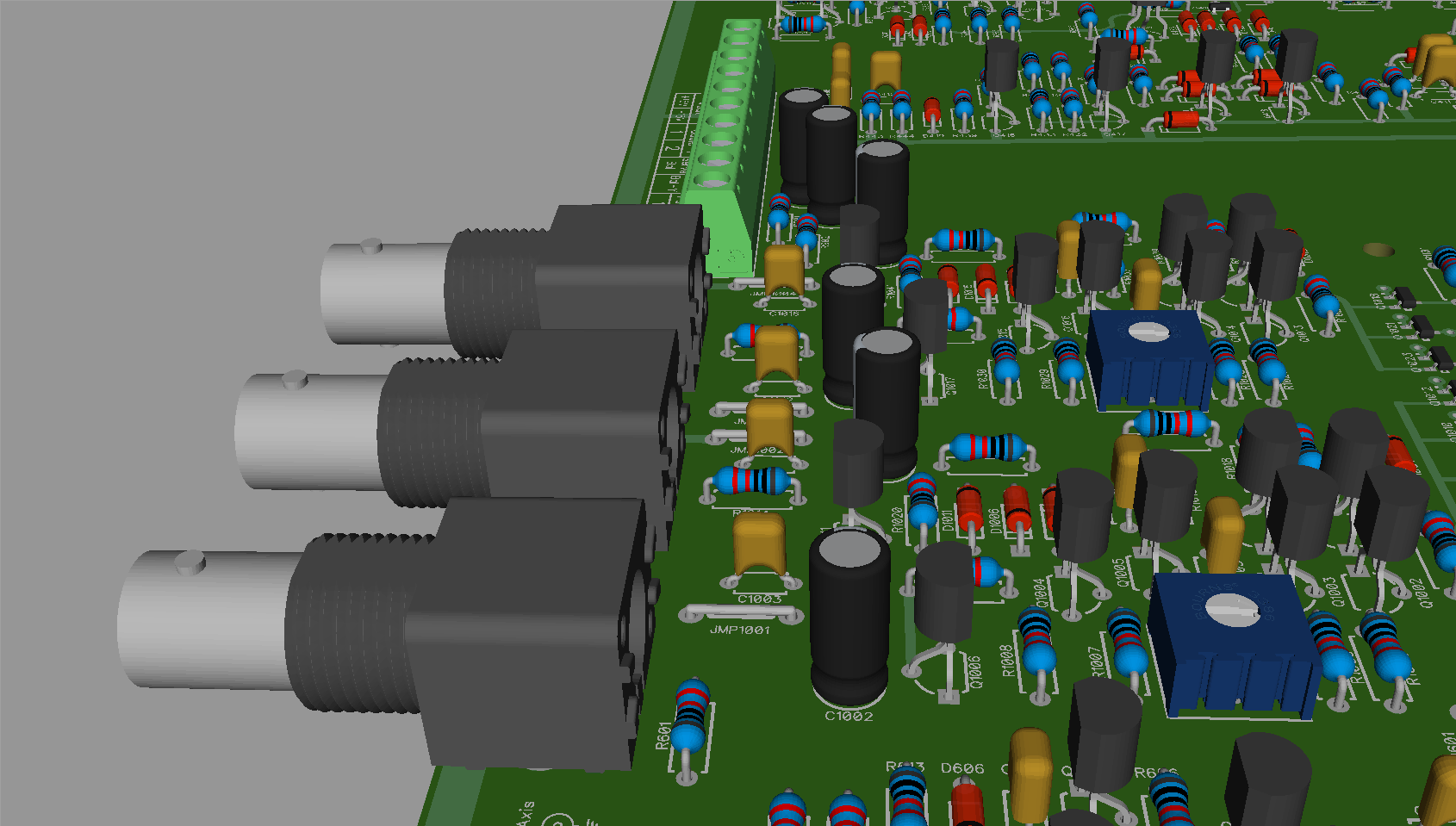
Added short 20AWG jumper wires between the main power bus and each section, instead of direct trace connections. This will allow the ability for the user to disconnect, use a separate external supply or perform current measurements on each individual section, which should be super handy for debugging! It also allows me to easily route other nets between the two pads of the jumper, if needed.
I only plan to use these for power connections to each section. They can be seen in the following renders: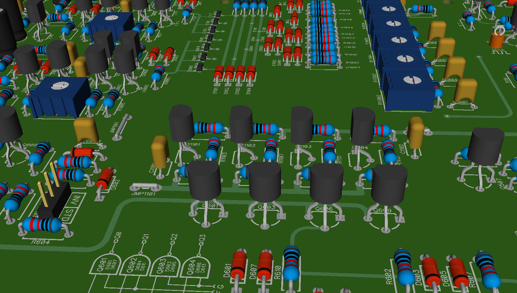
At my current rate of progress I should have the first full layout PDF up for review by the end of the weekend. -
Could have just as well made them 0.1ohm resistors, so placing a volt meter on them will allow current measurements.
-
Could have just as well made them 0.1ohm resistors, so placing a volt meter on them will allow current measurements.
Well, 100mOhm might be too low considering the current draw of a lot of the sections. 500mOhm might be more practical, however there are some complications with that; in some places, I have to daisy chain the power traces between sections, which means you could end up with a significant voltage drop. Using #20 wire works out a lot better, since the resistance is fairly low (tens of mOhms).
Originally I was going to use 0Ohm resistors, but ultimately a piece of wire is a lot less expensive, they have a very low voltage drop and allow a handy place to clip a probe as well!
You can still replace any of the wire jumpers with current shunt resistors if you want, as the footprints I've made will accept standard 1/4W resistors. (For footprints with 3.81mm or 5.08mm pad spacing the resistors could be placed in the vertical orientation, for 7.68mm and larger footprints the resistors could be placed in the normal horizontal orientation).
-
Nice to see the board layout approaching fruition. Here is where I am currently at with the Video version. The paddle generators are complete, as is all of the control logic and the game is now completely playable. The photo below shows the video display immediately after power-up. A Power-on-reset timer automatically sets the score counters to zero and the system is put into the default mode; the velocity integrator is discharged and the ball movement integrators are set and held to initial conditions which result in the ball being presented stationary in the middle of the court. The system is now just waiting for the "serve ball" button to be pressed to initiate game play. When a player misses the ball and it travels off either the left or right hand side of the screen the opponents score counter is incremented.
There currently aren't any sound effects however, which really does make it a bit boring! The sound circuitry is up next. And after that all that will be left is the (already proven) video colour encoding circuitry and the power supply.
-

 Complete Madness!
-
Originally I was going to use 0Ohm resistors, but ultimately a piece of wire is a lot less expensive, they have a very low voltage drop and allow a handy place to clip a probe as well!
You can still replace any of the wire jumpers with current shunt resistors if you want, as the footprints I've made will accept standard 1/4W resistors. (For footprints with 3.81mm or 5.08mm pad spacing the resistors could be placed in the vertical orientation, for 7.68mm and larger footprints the resistors could be placed in the normal horizontal orientation).
Is it possible to make them all the same footprint, say the standard horizontally mounted 1/4W resistor footprint?
The standard 1/4W resistor footprint I use everywhere on the board has a 0.75mm/1.5mm hole/pad size and 7.62mm spacing between pads. For the jumper wires I'm using a 1mm/2mm hole/pad size and have 5 different footprints with pad spacing from 3.81mm to 15.24mm. 20AWG wire is about 0.8mm in diameter, so it needs a bigger hole.
Like I said, a normal 1/4W resistor will still fit just fine in the bigger hole if you want to go that route, though you might have to install it vertically any place I used the 3.81mm or 5.08mm pattern, which I've only had to do in a few spots.
If you're worried about having to use a different size drill when making the boards by hand, it shouldn't be that big of a deal, really, as there's only about 20 or so jumpers on the board.
Here's an example image I made showing all 5 sizes of the footprints I've got with 30mil traces running under and between them: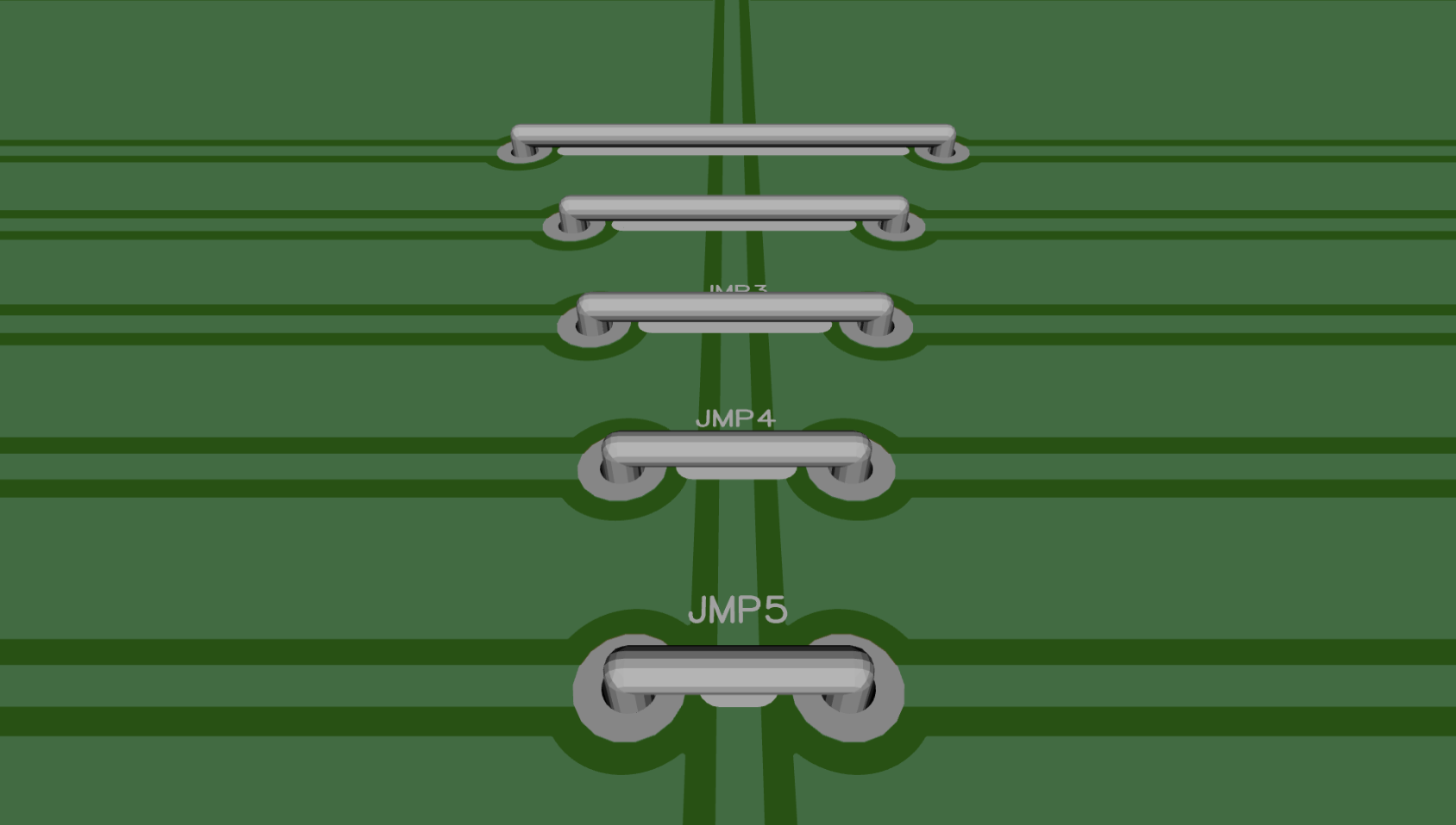
I'm nearly done connecting all the sections to the power bus and the 7.62mm footprint is the most common by far, with 5.08mm being used three places and 15.24mm being used one place.
Keep in mind that 0Ohm resistors aren't actually zero ohm. Carbon ones can be close to 1Ohm in some cases! Metal film ones can be 250mOhm or more. I'd highly recommend using a piece of at least 22AWG wire as the jumper to avoid a significant voltage drop on some of the more current hungry sections. (I will be including 20AWG jumpers in the kit. You can actually buy them pre-cut and reeled the same way resistors come, they're only a couple of cent and should save a good deal of time.)
Damn, that's looking hot! Can't wait to turn that into a PCB! :} -
Is it possible to make them all the same footprint, say the standard horizontally mounted 1/4W resistor footprint?
Just to clarify what I meant by being able to use a normal resistor in place of the wire jumpers: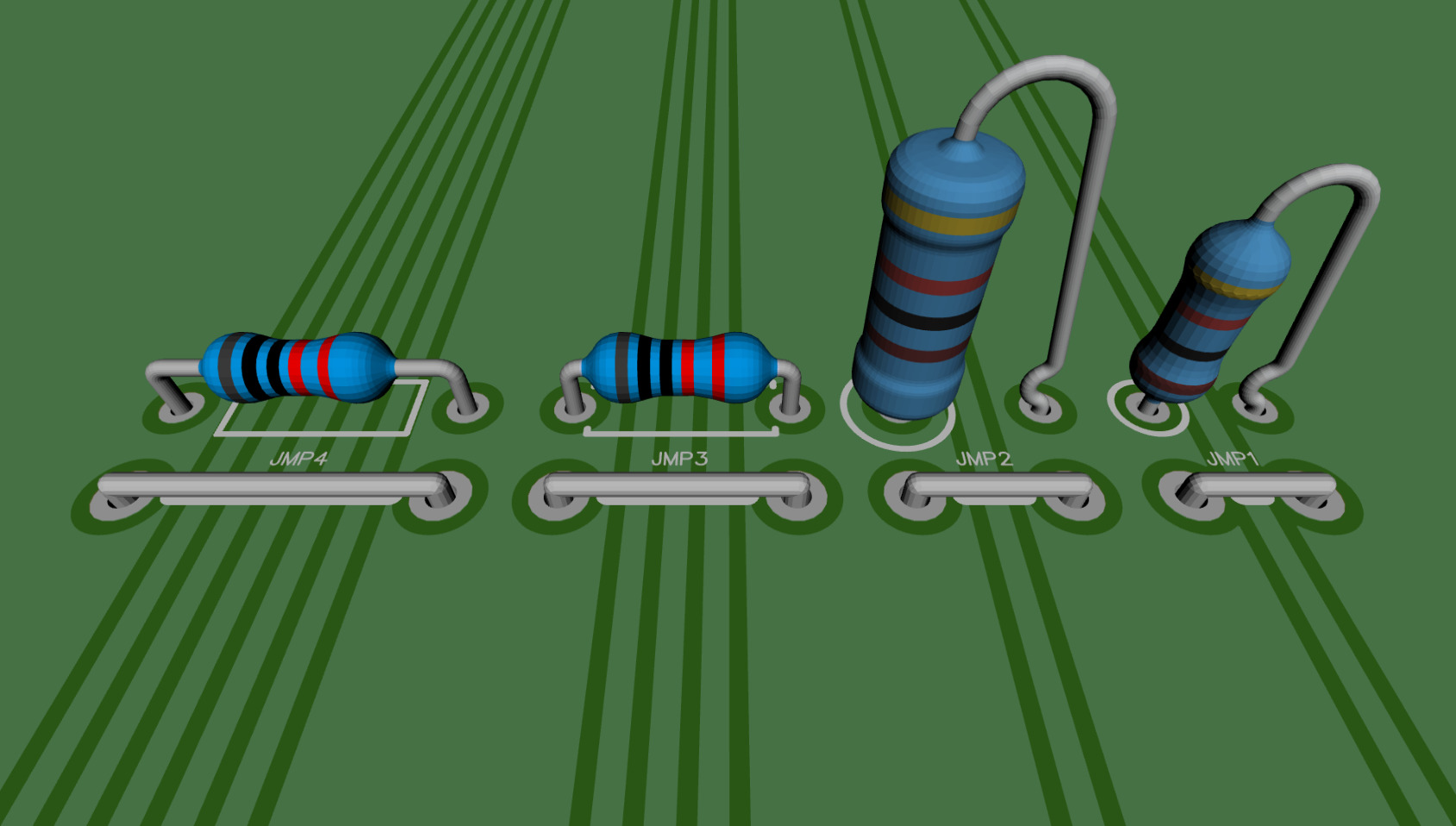
As you can see pad spacing is the same, so using resistors won't be an issue.
In other news, I'm getting closer: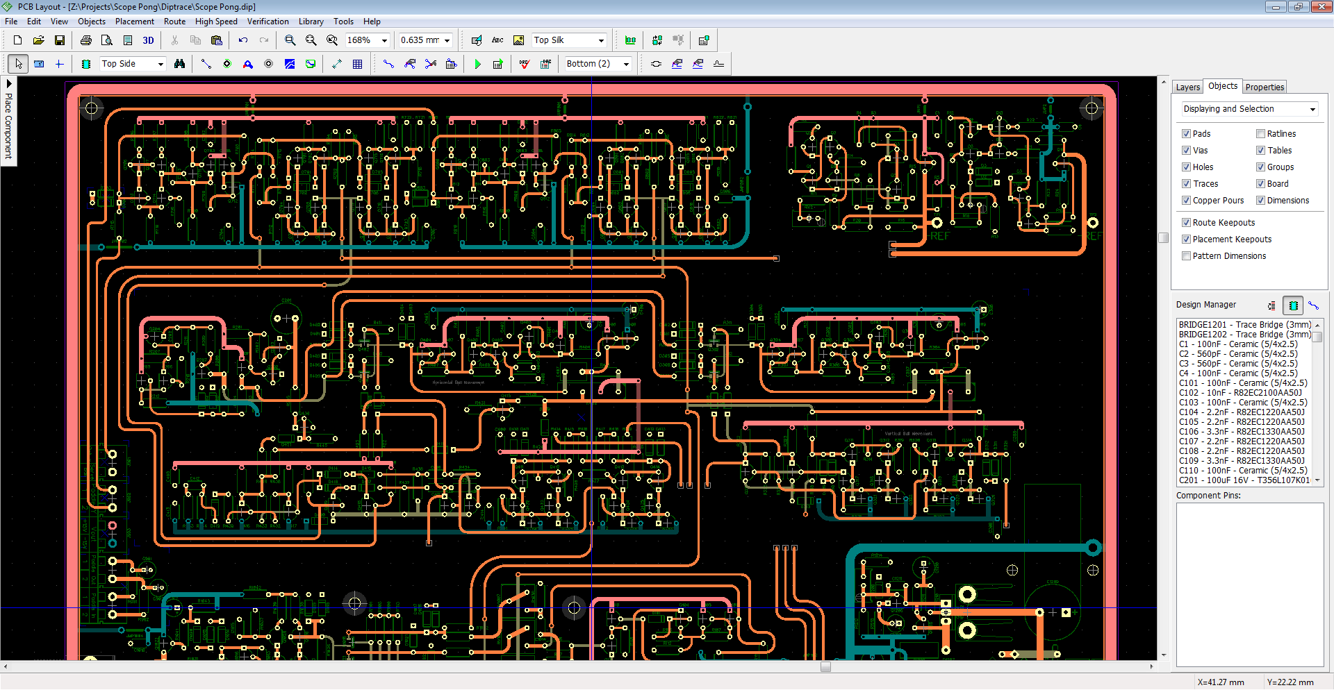
The external drive that I run my Windows 7 VM on died Saturday, so I spent a lot of time troubleshooting that instead of doing layout. Thankfully the new SSD will be here today (gotta love Amazon Prime).
Routing some of the nets has also taken a bit longer than originally anticipated. Now that I've got all the sections placed, I'm finding ways to optimize things, which means moving and rebuilding small pieces of some sections. It'll be worth it though, as I can do away with quite a few vias. -
No worries, Tim. Appreciate all the time you've been able to invest into laying out the board.
-
Is it possible to make them all the same footprint, say the standard horizontally mounted 1/4W resistor footprint?
Just to clarify what I meant by being able to use a normal resistor in place of the wire jumpers:
As you can see pad spacing is the same, so using resistors won't be an issue.
Sorry for the slow response - busy at work this week. My reason for asking if they could all be the same footprint was twofold:- If you were to replace with resistors for current measurement purposes, it's easier to get probes or clips onto the two ends if the part is horizontal.
- If they are all the same footprint they are easier to spot (you know what to look for).
It would also reduce the BOM if you were planning to supply pre-formed links as part of the kit.
Not a big deal either way - maybe I'm just a consistency freak...
-
Keep in mind that 0Ohm resistors aren't actually zero ohm. Carbon ones can be close to 1Ohm in some cases! Metal film ones can be 250mOhm or more.
That's interesting, I had always assumed they were just a solid piece of wire with a resistor form molded over. I wonder why they aren't.
-
Keep in mind that 0Ohm resistors aren't actually zero ohm. Carbon ones can be close to 1Ohm in some cases! Metal film ones can be 250mOhm or more.
A quick look on Digikey for 1/4W zero ohm resistors gives 11 results, some carbon film, some metal foil. All have resistance of 20 milliohms or less.
-
Keep in mind that 0Ohm resistors aren't actually zero ohm. Carbon ones can be close to 1Ohm in some cases! Metal film ones can be 250mOhm or more.
A quick look on Digikey for 1/4W zero ohm resistors gives 11 results, some carbon film, some metal foil. All have resistance of 20 milliohms or less.
I said some.
It generally happens with the cheap grab bags you get from eBay or Ali Express. In a lot of cases they simply remark the lowest normal value they produce (often 500mOhm or 1Ohm) as zero. Other times they're simply QC rejects that have a manufacturing flaw and are resold in these lots.
If you're purchasing direct from Digi-Key you should be alright. -
Keep in mind that 0Ohm resistors aren't actually zero ohm. Carbon ones can be close to 1Ohm in some cases! Metal film ones can be 250mOhm or more.
A quick look on Digikey for 1/4W zero ohm resistors gives 11 results, some carbon film, some metal foil. All have resistance of 20 milliohms or less.
I said some.
It generally happens with the cheap grab bags you get from eBay or Ali Express. In a lot of cases they simply remark the lowest normal value they produce (often 500mOhm or 1Ohm) as zero. Other times they're simply QC rejects that have a manufacturing flaw and are resold in these lots.
If you're purchasing direct from Digi-Key you should be alright.
Good to know.
Sketchy ebay stuff.
-
Just wanted to let you guys know I'm back working on the board again. I ended up having some work come up at the beginning of last week and haven't had any free time the past week. Now that things have calmed down I can finish the board up.
-
Wow I hadn't seen this thread yet! This is terrific stuff!
-
Just wanted to let you guys know I'm back working on the board again. I ended up having some work come up at the beginning of last week and haven't had any free time the past week. Now that things have calmed down I can finish the board up.
That's great to hear! Can't understand much of who it works but dang is it fun to watch you guys build this piece of artwork.
-
Just wanted to let you guys know I'm back working on the board again. I ended up having some work come up at the beginning of last week and haven't had any free time the past week. Now that things have calmed down I can finish the board up.
Thanks for the update, Tim. I still get a chuckle from your pretentiously polysyllabic profile prose. An amusingly astute archetype of alliteration it is. -
Thanks for the update, Tim. I still get a chuckle from your pretentiously polysyllabic profile prose. An amusingly astute archetype of alliteration it is.
Don't encourage him, he still has a job to do.