-
Working on a power supply. Just can't toss it without completely destroying it first. This PSU has almost no use and is out of warranty of course, so my lessons continue.
 Upon close-magnified scrutiny of the components nothing indicates failure, i.e. bulging caps, burned FETS, broken wires, fuse, etc.
Primary Symptom: When green wire is grounded at main terminal none of the computer peripherals receive 12V, 5V and/or 3.3V. However , I do receive 5v on the standby rail. So the 168vDC being supplied to the +5vstandby rail is going through this smaller transformer and providing the correct voltage. I guess I am getting something to the secondary side.
The 400V cap is only showing 168V(dc) (waiting on cap tester now). Thinking this cap should be somewhere around 350-375V. This is the first discrepancy I find in-circuit. My second concern is the main transformer is not getting any power at all (red rectangle on photo).
Question: If cap is good what in the circuit would prevent it from charging to an estimated 350-375V?
I have added a few pictures indicating general observations from probing.
Image Notes (below):
Yellow arrows show general flow from introduction of 120AC.
Red lines on photos showing the top is where the board splits and goes to the secondary side.
Purple marks on photo showing the bottom-side of the PSU also show flow of voltage from introduction of 120AC.
Would greatly appreciate any diagnostic suggestions.
-
Thanks for the reply. This unit was manufactured in Nov. 2013. It doesn't have the 220/120 switch mentioned. Although it does accept 100*240v 47-63Hz input. It is a 850w. Thanks for the article, I'll check it out.
-
The main "transformer" is a "Viking E216944-W H-P CWT 1209", for which I am unable to find any datasheet. Transformer has 6 terminals on the primary side and 8 terminals on the secondary side (DC side). (see bottom of board photo red rectangles for the terminals)
You mentioned an "IC" chip that brought this to mind:
I did look into WT7502 ("PC Power Supply Supervisor"). My understanding is that it looks for the correct voltages on input terminals before it will initiate power to actually turn the PSU on. NOTE I MIGHT BE MISUNDERSTANDING THIS COMPONENT. The green wire (on/off) that switches the power supply on and off connects to terminal 4 of the Supervisor. I also checked and did not find voltage on either V33, V5 or VSS (all input signals) to this Supervisor. I assumed the lack of input voltages is preventing the "Supervisor" from pushing power to the transformer/converter (Viking E216944 previously mentioned) so, I turned my search elsewhere for now. Kinda hard to suspect this supervisor as it is situated near the 12vDC output (to peripherals). If you can see the top view photo it is located just between where the blue (-12v) and black wires go into the board at the bottom-left of the photo. I assumed I was way off and moved closer to the primary side of the main looking for voltage to transform for the secondary side.
It has two rectifiers that convert to DC just after the second choke>
I greatly appreciate your food for thought on this; thank you for taking the time to respond. -
Is there anyway I can get you some full-size photos (about 16MB)? I did have a little time to do some more work today, but need plenty more time to catch up on researching the things mentioned.
Will try to answer all the questions this evening.
-
So these viking parts are transformers that lower voltage from 380vDC to working voltages of 12, 5 and 3.3 on the secondary side? Want to make sure I know what the components actually do.
-
?Optocouplers or Power regulators?:
I have identified three which straddle the primary and secondary sides of the board. Part number "L1213 817 B W" although I am trying to figure out what these are at this poi
Still working....
-
For the optos:
Can I probe the anode and diode terminals (pins 1 and 2) to determine if this side, at least, of the optos are good or bad?
I have made sure a fan was present (load) on the peripherals lines to ensure I would be alarmed at any changes while working. Wanted to make sure since the PSU's fan was removed with the case.Do believe I found a bad diode:
Neg to cathode and pos to anode:528
Reversed: 936
Faulty? Would need to remove it to get data.
Still working.... -
I am going back and correcting my posts as I learn.
So far:
1. 123AC going into the board through choke>>filtering cap>>choke>>filtering cap; then
2. 120AC into 2 rectifier bridges and 168 DC coming out of them.
Question: Does the 168DC out of the 2 rectifiers appear correct? I can't get data from the rectifiers due to heat sink. Not ready to pull for testing yet. If you guys think the rectifiers are working properly then won't test them. Still studying on the "boost" you both mentioned.
Essentially, I am getting 168VDC out of the two rectifiers. I don't understand the purpose of the cap "MEX JBN 105k450". (top right)
If you click the photo and then to the right at photobucket you can DL the image and zoom in to read the text.
-
I have made sure a fan was present (load) on the peripherals lines to ensure I would be alarmed at any changes while working.
One fan load may be not enough to satisfy the minimum load requirements of this rather large PSU. Or am I ?
?
-
Mess....verified through manufacturer the single fan should suffice.
PFC refers to pre-rectifier bridge(full)/DC conversion? -
Pulled the MOSFETS (below) and did a bench test here: https://www.eevblog.com/forum/beginners/proper-mosfet-bench-test/msg1166902/#msg1166902
Both are clearly working. Source terminals are connected to the large 400v Cap negative terminal.
Could rectifiers have anything to do with the cap not reaching the correct voltage? If, 123AC is going into the rectifiers (no id marks since they are pancaked into a heat sink) would the EXPECTED output value be 168DC?
-
After the ac input, two chokes, and two filtering caps, the AC hot and neutral come together through two SG1s. Can anyone explain what the EE's purpose was here?
Chip "GR8875R C2U01" (SOP 7), seems to be at the heart of this: www.grenergy-ic.com/attach/product/20120607130542_pic.pdf
Full size image:
https://postimg.org/image/smtd5jtz1/ -
1. Why not draw a schematic of what you have traced so far starting at the AC mains?
2. I would pull the data sheet on the PFC IC and see if you can read about what control and monitoring inputs it has and what its expected behavior is.
If you have gotten to the point of discovering that ICs model number and it has a public data sheet in a suitable language anyway.
3.When you say you measure a certain voltage I am not sure if that is true RMS or non-RMS AC or peak or what. If you had / have a waveform or more details than I have seen so far that might help.
4. Also we should know what your line voltage is in relation to the measured or displayed rectifier output.
A 100VRMS line sine wave voltage will have 100*sqrt(2) = 100 * 1.414 volt positive and negative peak magnitudes because the crest factor of a sine wave is sqrt(2) times the average value. I am not 100% sure what the RMS value of a full wave rectified sine is, but logic tells me it should be the same as the line RMS value since energy / voltage is not being lost if the rectification is perfect. Logic also tells me that the RMS of a sine that has half the peaks cut out by half wave rectification should be half of the RMS of the input voltage because half the signal is missing. So depending on your line voltage and your DVM you can tell if your readings are as expected. If your DMM measures frequency of mains signals safely then of course full wave has twice the nominal line frequency while half wave has half and unrectified mains has the nominal frequency.
1. Will certainly try to fit this into the troubleshooting. I suppose it would be much easier for the more informed (pretty much everyone here) to make suggestions that are always appreciated.
2. PFC IC power fact correction integrated circuit....uhmmm....where is that? I did find a GR8875 that I plan to look into.
3. RMS vs non-RMS or peak or....? Sorry, not an engineer by any means. Simply setting my DMM or DVM (FLuke 114 to Auto-V LoZ and it gives me anumber.
4. Sorry it is just above my head. I greatly appreciate the information though and the time taken to reply. Will see what I can learn about it. -
The PFC unit should either be along the left side or along the right side of the top of the PCB in the first post photo.
Then there is the PCBA off to the left side of the photo of the bottom side of the main board in the first post. Where did that come from?
The board off to the side has two large yellow and two large black wires going into it to supply DC. Then off to the side of that same board has most all of the 3.3 , all of the 5v and about half of the 12v signals going to the peripherals. -12v, PCG, and green (on/off )wire do not touch this board off to the side. -
Could be a bad diode, coulld be just something that is supposed to beeeeee in parallel with it for some reason.
You were correct. Pulled fro circuit and tested fine. -
PFC refers to pre-rectifier bridge(full)/DC conversion?
PFC stands for power factor correction. For most of the time, it is essentially a boost converter with current-voltage cascade control loop. It controls its real time current to track AC input's voltage, and it controls its average current based on output voltage.
The 168V clearly shows it is not working.
My fundamental understanding: Power supply on and "current" is being consumed by PC peripherals which the IC senses and a resulting voltage drop at the controller "chip" so the PFC circuit allows more power to be converted "filling" the PET cap (400v, 470uF) to maintain current DC power needs? -
1. Basically something in the over 300V but under 400V range is usually some indication that the PFC is outputting a boosted value. What is the peak of your actual mains voltage? Do you know?
I don't know if you're in Japan or UK or whatever could be as low as 90VAC up to 240VAC.
2. The PFC input would be something like full wave rectified mains voltage, and the PFC would implement a boost converter to boost the PFC VIN FW sine rectified pulsating DC waveform up to the DC bus peak voltage around 350V.
3. The secondary of the main transformer is not 12VDC or 3.3VDC directly but probably something that is somewhat higher than 12VDC as an AC signal and which is then synchronously rectified and filtered to make 12VDC from that. Depending on if it is a full bridge or half bridge or LLC or forward converter or whatever determines the waveform of your primary and secondar. There could be additional secondary and primary side windings as well.
Multiple secondaries if present may or may not be able to provide voltages that can be used to efficiently derive +12V, -12V, +5V, -5V, +3V, etc. ratiometrically relative to the just over 12VDC AC equivalent most important seconary output.
Additional primary windings can be used as a bootstrap / power supply winding to feed back and supply a suitable voltage maybe in the range of 5V to 40V to the PFC converter IC that needs to be powered by something, usually in the 15V-20V or so range maybe depending on implementation.
So a defective power supply for the PFC IC could also result in PFC failure.
1. Sorry the only values I can tell you with confidence is 123vAC input and the PET cap is 168vDC In US. No oscilloscope.
2. So, the AC wave is being rectified into DC but it is not getting boosted? Just making sure I understand.
3. This makes sense to ensure you maintain the desired vDC when power is "drawn" through transformer. Hope this indicates a vague understanding. The main transformer has 6 terminals on the primary side and 8 on secondary side. -
Trying to keep up with you.
PFC IC?:
Note: the heatsink and FETS that I tested earlier are still removed.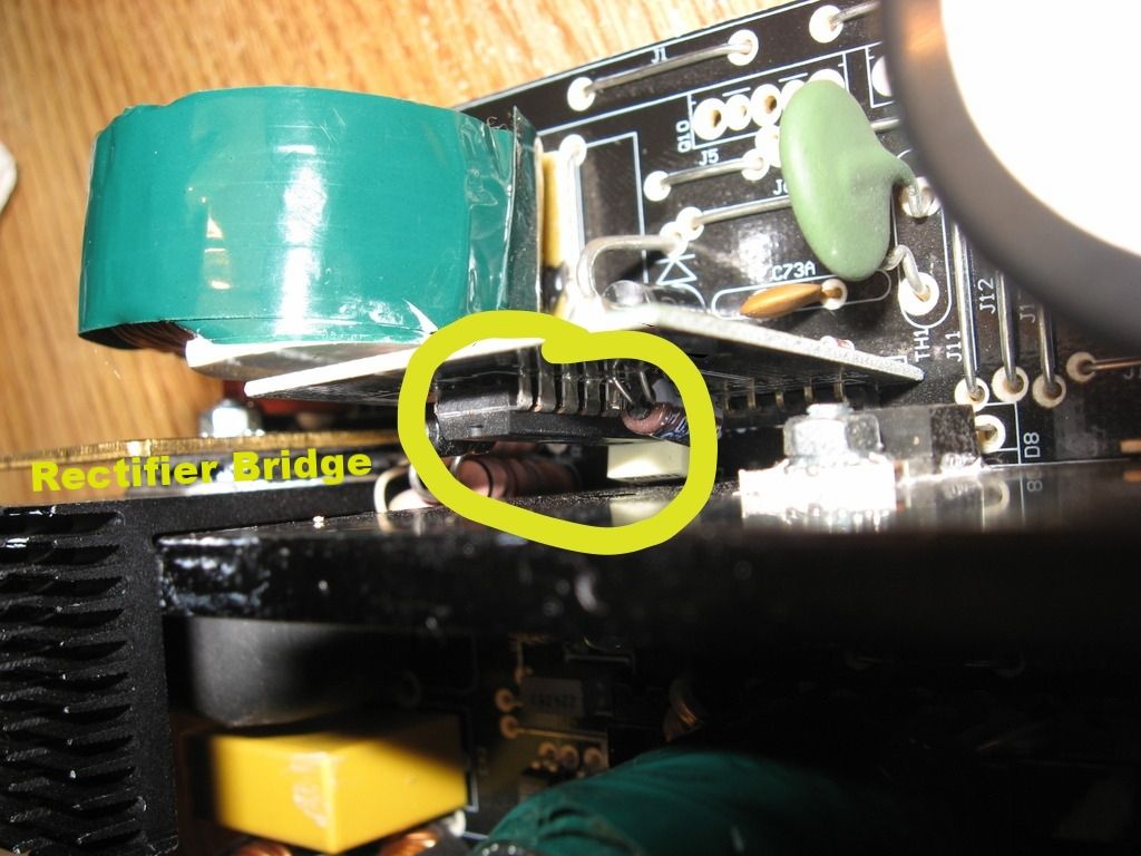
Another angle: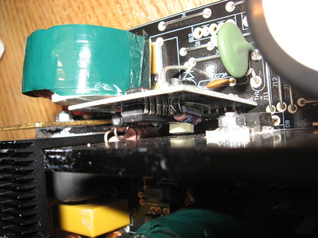
-
So you have no oscilloscope and safe way to use it and appropriate probes etc. measure mains related signals with it?
Unfortunately no. -
WHERE did you measure the 169V? I was hoping for some little bit of a schematic up to the PFC input.
169V across the 400V main DC bus storage capacitor means the PFC is not operating to charge it.
169V across the mains rectifier going into the PFC before the boost coil is probably normal.
After the AC/DC rectifiers: https://postimg.org/image/8mvz8jtn1/ Make sure to click on the picture so you can zoom in.
I marked that main cap as 400v so you would have perspective of the board. Measuring the voltage is 168 across the + and - terminals of the cap.
You can download that image to your PC then open with paint and draw on it...then post if you have time. -
1. Also isn't that another IC I see on the back side of that same board that should be more visible? What is that?
1. the other side of the vertically opposing board has "CWO3X f53028J5 150" (8 Pin) and I will need to verify that lighting is terrible at the moment.
2. Is that a DIP packaged chip? Looks like it has more than 4 pins on a single side of the package so more than 8 total for that IC?
3. EDIT: Please see the edited version of my post with various images of block diagrams above, I added an annotated one that should show the flow and be hopefully able to be related to the circuit you are seeing in generality
2. The main suspected PFC IC is 16 pinon the vertically opposing board.
3. Awesome... PFC AFTER ( I wasn't sure) the rectifiers.
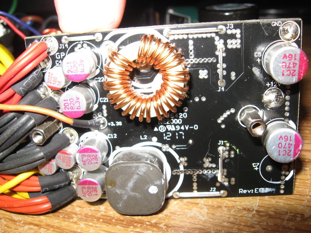
Is this a boost coil?: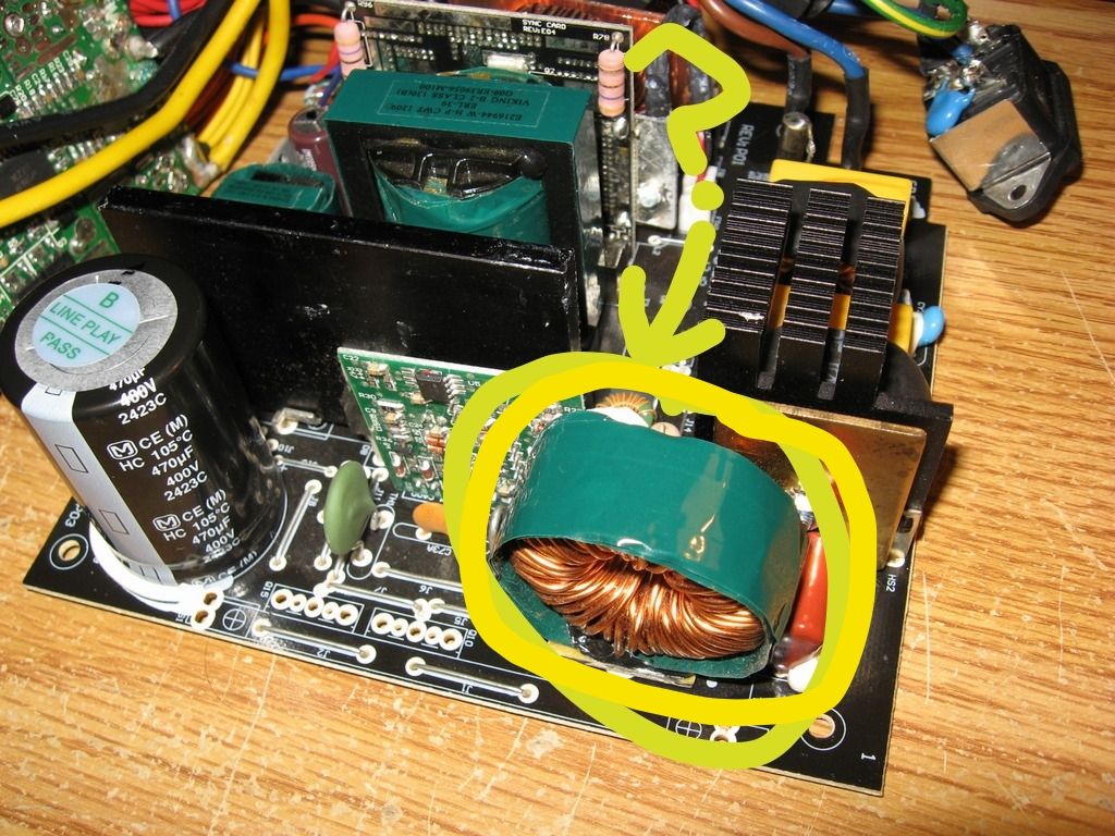
-
PFC IC?:
I would first try to find whether the PFC circuit is dead, or the secondary side didn't signal the PFC to start at all.
As I said before, probe the optocouplers. One of them should be connected to that PFC controller daughter card.
While powered on (with green wire grounded), use your DMM to measure the input side of the PFC opticoupler (input side means secondary side, not mains input side, for this particular optocoupler).
*I assume you know what you are going to do. Slipping your finger and touch mains side while powered on can and will give you a nasty pick-me-up, or worse, put-me-down, so practice your best cautious, or better, solder a pair of wires from optocoupler to your DMM's test leads, and stay away form it.
I did a simple diode test across pins 1 and 2 and did get an inconsistent reading on U5(see photos), but tracing the board this seems it could pose a problem only after the boost in the PFC. Definitely going to look at them as soon as I get the PFC boosting.
I will conduct a test (bench if needed) of the optos after I get it put back together. This may never happen if my probes slip [bang and smoke],
at :54 seconds is applicable
Tomorrow I might pull that heat sink blocking the suspected PFC controller to get the datasheet. Is that something I might be able to buy somewhere? -
To me, it seems like U3 is PFC control optocoupler.
I have this off at the moment:
Power on the system, short green to ground, and probe input of U3 (the pins on secondary side), tell me the voltage.
It should be ~1.2V, give or take, for a working PSU. If its voltage is very low, almost zero, then your problem is on the secondary side.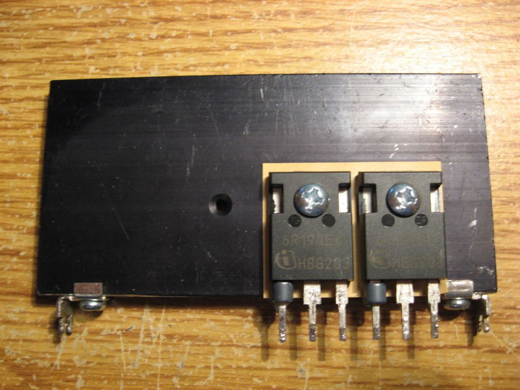
Going to get that PFC IC code tomorrow after I pull the other heat sink blocking access, much easier than pulling the vertical board with the PFC IC on it. Can ALMOST read it with dental mirror.
To me, it seems like U3 is PFC control optocoupler.
Power on the system, short green to ground, and probe input of U3 (the pins on secondary side), tell me the voltage.
It should be ~1.2V, give or take, for a working PSU. If its voltage is very low, almost zero, then your problem is on the secondary side.
-
I just need to trace the leads from this "doughnut" and see where they lead me. ugh...sleep
-
Oh cool, I have always been curious how the PFC was working in these supplies. Thanks for posting these! One learns something new every day.
-
PFC IC Controller
(CM6800TX): "The CM6800 is a controller for power factor corrected switched mode power supplers."
Working on rudimentary schematics now.
Datasheet: https://www.google.com/url?sa=t&rct=j&q=&esrc=s&source=web&cd=1&ved=0ahUKEwiimMbz2urSAhVK2GMKHUS5D2oQFggfMAA&url=http%3A%2F%2Fwww.champion-micro.com%2Fdatasheet%2FAnalog%2520Device%2FCM6800.pdf&usg=AFQjCNG0hlXFKyG8nqJ015hesi3hfDp6KA&sig2=nxxLSTTSYGhoIpgRVY0iBA&cad=rja
Click for full size:
-
Did a bit of tracing today trying to focus on the PFC and IC hoping to figure out the circuitry. Maybe, I should just call Corsair and ask. Some of the symbols were too complex, so I just made a note or a small pic when I didn't know what the "thing" is/was.
I was able to score one more identical broken power supply and one more very similar broken PSU from the same manufacturer! Should be a very inexpensive lesson in microelectronics.
Will catch up on responses later today I hope. Click image below then click it again when it takes you to the new page to really zoom in close.
-
Does the 25v Cap look burned?:

Other Side of PFC Board:
Will start tracing at the optocouplers next time.
-
The color is like ink that runs across onto the PFC controller next to it on the left-just noticed in the photo. Was sure hoping I could find a problem somewhere obvious, replacing that PFC controller does not look like fun. Getting my hand pump on there does not want to extract the solder with the tight pin configuration. Oh well that is in the future.
Ordered cap tester a few days ago....going to be a long wait. -
I would assume it more likely that some issue that will not involve replacing the PFC IC or module would be more likely.
I think the thing to do while the system is apart is to
(a) Inspect it.
(b) trace it to know the most relevant connections
(c) identify / arrange possible points of in-system test access to relevant nodes so you can check the states at run-time
(d) perform any individual component or sub circuit testing that seems possible and necessary.
Otherwise soon I think you should put it back together and then identify the operational voltages at the control and signal nodes that you will have identified so you can determine a cause of why the PFC has no output.
Then, having established the circuit input that may be at fault, look for a way to prove / repair that aspect.
This is music to my ears.
While tracing the opto circuits on the primary side I was thinking about pulling them for a simple bench test in a bread board.....only 4 terminals and I have a few major components already off. Although not sure how sensitive they are to heat.
Really good article on the power supplies explaining PFC. Got a good laugh at a complexity comment on page 3, "Reduced complexity for active PFC...." Circuitry on this board is wow.
I noticed that when you click my thumbnail images posted at postimg.org you can actually download the original in full resolution and zoom in. Excellent website for the larger photos.
-
Here is some of the optocoupler circuitry:

-
I originally thought this "chip" had some burn, but not so sure now. Wanted to post to get other opinion(s).

-
Below is what I pulled so I could read the vertical board with the PFC controller. Have not traced their curcuits yet, but thinking I might after the optocouplers on the secondary side. It is situated just before the main transformer.
CET: https://www.google.com/url?sa=t&rct=j&q=&esrc=s&source=web&cd=1&ved=0ahUKEwj78t_51OvSAhUK64MKHakDAGoQFggcMAA&url=http%3A%2F%2Fweb2.cet-mos.com%2FPDF%2FCET-MOS%2FTO-220-263-N%2FCET_CEP04N7G(F).PDF&usg=AFQjCNHW_7K6QYxFmb5sRLdgDZqz6N15-Q&sig2=GisGAHP7kF-QntmmhUEDQw&cad=rja
K18A50Ss: https://www.google.com/url?sa=t&rct=j&q=&esrc=s&source=web&cd=8&ved=0ahUKEwjwg9Se1evSAhUZ3YMKHV18AyoQFgg0MAc&url=http%3A%2F%2Fwww.farnell.com%2Fdatasheets%2F2007926.pdf&usg=AFQjCNFLBqJfIpw2T0uZYkEqygiBzE_K3g&sig2=pP7an8DyFphGSEAU2ulzEQ&cad=rja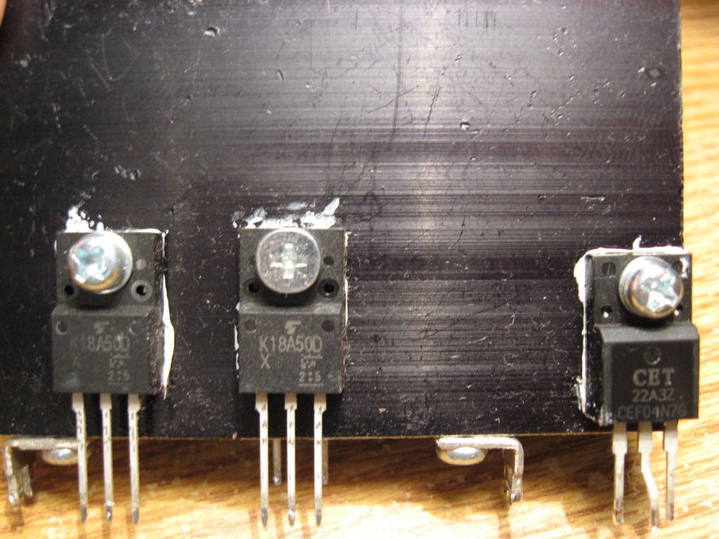
EEEwwww a boost diode below. https://www.google.com/url?sa=t&rct=j&q=&esrc=s&source=web&cd=1&ved=0ahUKEwisiZet1OvSAhUj7IMKHSobAVUQFggdMAA&url=http%3A%2F%2Fwww.st.com%2Fresource%2Fen%2Fdatasheet%2Fstth506d.pdf&usg=AFQjCNFS8vimgpgu6ap69WgtKCawYb2jQQ&sig2=UA-LKOvnOhomaBFX3afpQg&bvm=bv.150475504,d.amc&cad=rja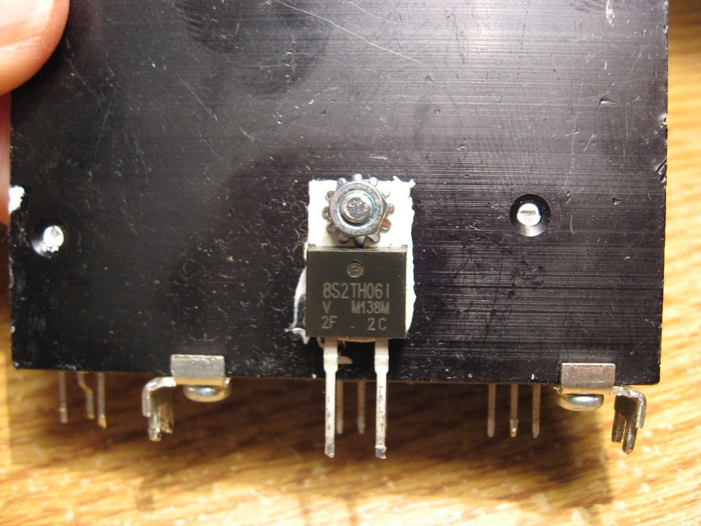
-
Boost diode ^^^ tests good "854" with negative probe to terminal 1 and "1" with negative probe to terminal 2-red always on other terminal.
-
Corsair CX500 PSU Repair - YouTube
Interesting fix for sure; very informative, especially for that PS229 chip. He did have power on all of the rails, where I had nothing. I can sure see something like that as one possibility with mine.
I wonder if that PS229 will fail prematurely since he had to increase the voltage through the pin to get a "signal" across to the other side....? -
Fuse is/was a ceramic 250v 12A; "LF.T12AH250VP"
Is it slow-burn or fast? -
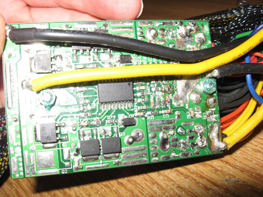
Running out of steam. Eliminating all the small resistors now and trying to get just the main things like transistors, optos, transformers, caps, and output circuits to that sub-board. It appears the main board is supplying +12v+ to that board off to the side which then supplies +5v and +3.3v to peripherals.
*Some peripherals still receive +12v directly from the main board.
-
The second PSU with the same model number arrived, but it is from 2011 and the board is way different.
-
Here is the board off to the side:
-
So the "T" in "F.T12AH250VP" stands for time-delay/slow-blow.
Good link on the matter: http://www.instructables.com/id/How-To-Identify-And-Replace-A-Blown-Fuse-1/


