-
Help Required - Repairing a Logitech Z906 Speaker
Posted by
Amarbir[Lynx-India]
on 12 Jun, 2012 19:26
-
Hello Guys ,
Got One Z906 From My Client .Opened The Woofer That Has all the electronics and boy i am impressed .My testing shows that due to a lousy UPS he has blown up the stage in the primary till the Rectifiers .The rectifiers seem all ok .Not tested anything beyond that .The is what i think is wrong need some advise here
1 : AC input goes through 2 fuses in both neutral and phase supply Both Blew Up.Then There was a component With a Marking "RV1 " .I suspect it should be a RDN rated at 275 volts or something .It can /cannot be a thermistor [ ptc ] ,But God Knows ,This Too Blew Up And I See a half inch pcb just becoming toast .Then the Neutral and phase supply had a capacitor i have no idea what it was its just melted due to rv1 component blasting .After this it was the choke that seems fine ,then the path routes to another capacitor like the capacitor i had just mentioned [ Will this capacitor after the choke and before the choke be same ? ,I do not think so ] ,The One after the choke is 1.0k275v-x2 . Then again we have a choke that seems ok too and then the supply goes to the 4 rectifiers ,they seem good too .so i suspect rest will be good too .please help me find what there in the rv1 and the first capacitor .Any idea i can make it work by just connecting the choke to the supply the first one but then this is not good repairing

-
#1 Reply
Posted by
T4P
on 12 Jun, 2012 19:46
-
It's not gonna help you or us if you don't post any pictures
And if you aren't too sure, those are definitely Class X2 and Class Y2 caps for EMI filtering and the like
http://www.justradios.com/safetytips.html
-
-
It's not gonna help you or us if you don't post any pictures
And if you aren't too sure, those are definitely Class X2 and Class Y2 caps for EMI filtering and the like http://www.justradios.com/safetytips.html
Sir ,
I Will Read This Website And Post The Pictures in The Morning Its 2:00 Am Here Lol [ India ]
-
-
It's not gonna help you or us if you don't post any pictures
And if you aren't too sure, those are definitely Class X2 and Class Y2 caps for EMI filtering and the like http://www.justradios.com/safetytips.html
Sir ,
Please Find The Pictures Of This Busted Unit .Both The Fuses values i have a idea as they are printed on pcb .No Idea of the RV1 and The first cap that looks similiar like the other cap "Yellow Colour " .The Unit can surely work "IMHO" With the Two components but They are there for a reason and i would not like to change that
-
#4 Reply
Posted by
Rerouter
on 13 Jun, 2012 13:10
-
the 2 yellow things are big mains rated multi-layer ceramic caps, class x2,
as for what blew up, i could only imagine something like a Metal-oxide-varistor making that big a scorch mark, when you exceed the rated voltage they short themselves to blow the fuses, and in the process can dump out a few hundred watt for a short moment
-
-
the 2 yellow things are big mains rated multi-layer ceramic caps, class x2,
as for what blew up, i could only imagine something like a Metal-oxide-varistor making that big a scorch mark, when you exceed the rated voltage they short themselves to blow the fuses, and in the process can dump out a few hundred watt for a short moment
Sir ,
I Read With Great interest the link Mr Dave had send me in this post "I suggest everyone should read that " . I have checked it again .The RDN/MOV is one of the components .I plan to use the 275 Volts rated one this time .The Capacitor Surely is a AC Live To Neutral Type It Has to be X2 .My Question is Can Someone Tell Me What Was The exact X2 capacitor value in pic 3
-
#6 Reply
Posted by
Kilroy
on 13 Jun, 2012 15:08
-
My Question is Can Someone Tell Me What Was The exact X2 capacitor value in pic 3
Sure...1uF.
-
#7 Reply
Posted by
SeanB
on 13 Jun, 2012 15:44
-
1uF 275VAC class X2. You can use almost any value between 0.47uF to 1.5uF 275 VAC that will fir the pin spacing. the actual value here is not very important, as long as it is higfh enough to provide some filtering.
Good thing the MOV was fitted, it definitely gave itself heroically to save the rest of the circuit.
-
-
Hi Guys [ Everyone ] ,
Thanks For Making My Task Easier ,I Appreciate That ,Would Get Back To You folks With The Repair Job With Pictures .
-
-
Hello Friends ,
This is What i did .Took 2 fuses 250 volts 6 Amps and 2.5 amps .Fixed Them In the start of This circuit .Then Connected a 14D431K Varistor [ MOV ] In Parallel .Took Out a Old X2 Same Microfarad But 250 Volt Cap From a Old Monitor PCB Plate .This was much bigger then the one that was busted .So i gluesticked it on top of the other X2 cap And connected the same with wires to the MOV in parallel .The output then crossed a choke and was again filtered by the second X2 .As soon as i was starting the unit the Fuse section was going in flames again and again .Nothing was getting busted but [ I did remove the second choke after the second x2 cap ,so that the primary smps voltage was even reaching the rectifiers ] . I could not solve the arching in the busted section of the pcb .Finally i cut all the tracks there and made a 1 inch hole and rearranged the fuses and voila "The circuit was alive ".Fitted the second choke back and the circuit was alive .Thanks to all of you who guided me in this and the once who though to write something but never did and the once who just read and went off ;-)
PS : Let The Pictures Talk
-
#10 Reply
Posted by
Rerouter
on 20 Jun, 2012 02:17
-
a few thoughts come to mind, HEAT-SHRINK!, TAPE!, SOMETHING!, those contacts will be live, at least cover them so that if your glue fails you don't re-blow your fuses, or much much worse,
-
-
a few thoughts come to mind, HEAT-SHRINK!, TAPE!, SOMETHING!, those contacts will be live, at least cover them so that if your glue fails you don't re-blow your fuses, or much much worse,
Sir ,
Before i Did the final inspection i did all that you advised .
-
#12 Reply
Posted by
Rerouter
on 20 Jun, 2012 13:30
-
i wanted to be safe, as your images showed no sign of anything,
there isnt enough people who know which end of the soldering iron to hold to risk having them zap themselves

-
-
Hi,
My Z906 subwoofer doesnt work and smells as burnt when AC connected. How do you open it to see the pcb? I got all screws but seems imposible to open from the back side....
-
-
Hi,
My Z906 subwoofer doesnt work and smells as burnt when AC connected. How do you open it to see the pcb? I got all screws but seems imposible to open from the back side....
Well,
Treat It Like a Wife Not a Girlfriend
.Only a Screwdriver is Required To Open The Same .Where Are You From
-
-
Hi, I am writing from Spain.
After making some stripes while trying to separe the back metal piece from the box I hope my wife will no suffer so much...

Do I have to get the whole metal piece or only the plastic piece (the one where connectors are located)?
Enviado desde mi LG-P990 usando Tapatalk
-
-
Hi, I am writing from Spain.
After making some stripes while trying to separe the back metal piece from the box I hope my wife will no suffer so much...
Do I have to get the whole metal piece or only the plastic piece (the one where connectors are located)?
Enviado desde mi LG-P990 usando Tapatalk
Well,
i do not remember but check out yu can clearly see you can remove all screws and whamm it comes our .Its connected to back using a glue type sealant .you have to use some force .
-
-
Perfect, the problem was the glue.
Now the new problem calls burnt pcb close to the transformer... is there any schema to know which were the burnt pieces? If not, do you know if logitech sells pieces
-
-
Perfect, the problem was the glue.
Now the new problem calls burnt pcb close to the transformer... is there any schema to know which were the burnt pieces? If not, do you know if logitech sells pieces
Hello ,
I and all will appreciate a complete picture of the power supply block please .i just repaired one and do not remember everything now
-
-
Like this is ok?
-
-
2 Pictures from the other side
-
-
Sir ,
How Good Are You in repairs this repair would depend on this question .If you like to understand how to repair smps i would recommend you get some book and try this one .Or give it to a repair tech doing smps repair since a few years .
-
-
Hi, I do not have much experience in these questions, but I'll find someone that will do it for me. Do you have schematics and info about reference of burnt pieces?
Enviado desde mi LG-P990 usando Tapatalk
-
-
Hi, did you find schematics?
Enviado desde mi LG-P990 usando Tapatalk
-
#24 Reply
Posted by
TheHiFi
on 01 Nov, 2016 12:16
-
Hi, I need some help with logitech z906's psu board components. I am looking for help with these components values: R37;R25;R24;R22;R21;C7;R13;C61.
-
#25 Reply
Posted by
Skimask
on 02 Nov, 2016 02:04
-
Who did the soldering?
-
#26 Reply
Posted by
Rerouter
on 02 Nov, 2016 08:20
-
Looks like only R25 is vaporised, R24 looks to be shorted to his neighbor with a small piece of wire. which based on the numbering leads me to think caused R25 to blow.
For a shot in the dark, i would imagine R25 could be a "131" from his neighbours, meaning 130 ohms,
But definatly get some desolder braid and clean up those areas before you reapply power.
-
#27 Reply
Posted by
TheHiFi
on 02 Nov, 2016 11:02
-
R44, R37, R25, R21, R22 these resistors are connected in parallel (as far as i can see), one end of resistors is connected to mains capacitor negative terminal and the other end is connected to two mosfets(fqpf9n90ct) source legs. (sorry for bad english)
-
#28 Reply
Posted by
Zeth89
on 11 Jan, 2017 20:14
-
Hi everyone! im new and im here looking for help with my z906 psu, i have a missing capacitor, it blew and i dont know it value, i don't have a spare part so i can't messure it, it will be awesome if someone of you could help me try to repair my z906, as I can't find a psu replacement either you guys are my only hope, the capacitor missing is the "C45" in this picture wich i find on this forum, ty all for your help and sorry for my crappy english
i leave my email here if needed
Zeth89@gmail.com.
Pls note that the picture i am using is not from my z906, it is a picture i took from this topic, my specific problem is the missing C45, (black square) ty again!
-
#29 Reply
Posted by
Rerouter
on 12 Jan, 2017 07:14
-
based on the size i would imagine 1-12uF 50V XR5 ceramic capacitor, would really need an image of what the other side of "TP32" has on it to be certain.
-
#30 Reply
Posted by
Zeth89
on 12 Jan, 2017 14:07
-
Hi Rerouter and ty for your help, i took a couple of pictures of what is on the other side of tp32, and it seems to me that is a couple of 3.3k resistors
-
#31 Reply
Posted by
Zeth89
on 15 Jan, 2017 21:06
-

:help:
-
#32 Reply
Posted by
Rerouter
on 16 Jan, 2017 06:56
-
The location of the fault doesnt seem like it will be the main cause of your issue, that area seems to be a number of high wattage resistors,
The capacitor while still being my old assumption is a symptom
I would measure the resistance of all of those resistors on the top side in that section, i would think 1 has gone high resistance and applied too much voltage to the capacitor.
-
#33 Reply
Posted by
Shock
on 16 Jan, 2017 10:03
-
Check for dry joints as well.
-
#34 Reply
Posted by
Zeth89
on 16 Jan, 2017 21:00
-
ty for your replies, I'm thinking humidity did this, since it was a stored working unit, it was stored for at least 6 monts, then i sold my main 5.1 hometheater, so i was going to use this z906 to replace it, but when i was going to use it, it blew, I opened it and it has alot of humidity on it, i cleaned it with thinner but i think it wont turn on without that capacitor (c45) that blew, i wanna replace that c45 and see if i can make it work, but i dont know what is the value of that capacitor, as i dont have a spare psu to mesure it, what you think i can do? can it be the 1-12 uf ceramic 50v capacitor as someone told me? but wich one? i wanna give it a try. ty in advance
-
#35 Reply
Posted by
Rerouter
on 17 Jan, 2017 01:07
-
Let's say 4.7uf,
-
#36 Reply
Posted by
Zeth89
on 17 Jan, 2017 06:36
-
Let's say 4.7uf,
Do you think it wouldnt have big impact if it isnt the exact same value on that cap? in case that's the reason it is not wonking.
also, i can see another capacitor that looks pretty similar en the board, the C60 it looks like it can be the same value, do you think i can take it off the board to know its value? ty in advance
-
#37 Reply
Posted by
Rerouter
on 17 Jan, 2017 07:16
-
certainly,
Where it is in the circuit, atleast to me looks to only be a noise filtering cap (High frequency noise, not a normal smoothing cap),
Still i will stress, i do not think this capacitor is the main fault, i believe it is only a symptom of another fault. Did you check out those resistor values? the way that capacitor fails, atleast to me looks like it saw a gross overload of voltage.
-
#38 Reply
Posted by
ciine
on 20 Jan, 2017 11:54
-
I want to make another power suply system for the Z906.
Please help me with:
-level output source before and after starting
-diagrama signals for TEMP3, TEMP RET, nPWR_OFF, PSYNC1 AND PSYNC2
because I do not have physical , power source
Thank you
-
#39 Reply
Posted by
Rerouter
on 20 Jan, 2017 19:14
-
your going to need to give a bit more info,
So your missing the AC power board from inside the unit?
-
#40 Reply
Posted by
ciine
on 20 Jan, 2017 19:18
-
Today I started with another source Z906 system, source purchased from lcd-tv, but I want to know from you, who own a Logitech Z906 ok ,that provides accurate voltage to pin the original source HV_ pin power
What value is ? 50 , 60 , 70 v???
look the picture
-
#41 Reply
Posted by
ciine
on 20 Jan, 2017 19:21
-
your going to need to give a bit more info,
So your missing the AC power board from inside the unit?
Yes, I`m not have the main power
-
#42 Reply
Posted by
Rerouter
on 20 Jan, 2017 19:44
-
I cannot read the chips next to it, however i would strongly guess HV connects to one of the pins on those amplifier IC's, if so, then look at there datasheet to find the maximum rated voltage and go a bit lower.
-
#43 Reply
Posted by
ciine
on 20 Jan, 2017 20:02
-
I know the chip is tas5162 PVDD voltage is about 70v (max) normaly is 50v
http://www.ti.com/lit/ds/symlink/tas5162.pdf I want to know exactly what PVDD voltage feed company logitech
Now powered PVDD with 24 V and works ok, but with limited power
-
#44 Reply
Posted by
ciine
on 01 Feb, 2017 23:39
-
I resolved, I rebuilt a Chinese source for 200W at full power 400w
with the following voltages:
-5V 1A
12V 1A
-40v 10A
It works perfectly
-
#45 Reply
Posted by
ciine
on 01 Feb, 2017 23:41
-
-
#46 Reply
Posted by
gnanasekar
on 02 Feb, 2017 18:23
-
I faced problem in primary voltage section only resistors burned and at the same output section resistor also, if some help to find the values of the following resistors.
R5, R95, R119, R12, R8, primary section Voltage.
R79, R80 secondary section Voltage.
please, post the values for the following values.
-
#47 Reply
Posted by
w1r3d
on 27 May, 2017 17:41
-
Need help recognising R5 and R8 resistors too. Them are burnt. I think them are 3K3 5 W resistors (the rest of resistors around are from this value) but not sure. Please, if anyone has schematics or these resistors working the help will be very helpful.
Thanks in advance
-
#48 Reply
Posted by
TheHiFi
on 27 Jun, 2017 13:29
-
I measured these resistors on my z906 board and you are correct they are 3.3K
-
#49 Reply
Posted by
Zeth89
on 01 Jul, 2017 08:30
-
Today I started with another source Z906 system, source purchased from lcd-tv, but I want to know from you, who own a Logitech Z906 ok ,that provides accurate voltage to pin the original source HV_ pin power
What value is ? 50 , 60 , 70 v???
look the picture
I tested and +hv is 46v
hi all, today i tested the internal psu of my z906, and i can read all the 5v, 12v, and 46v from +hv
but my z906 is not powering on, the other cable that comes from the psu to the main board i can see theres a cable labeled "3.3v keep alive" and i can't read any voltage from that, may be that the reason is not powering on? o do the main board still power on with all that 5v/12v/and 46v from the other connector? sorry for my english, hope you can understand me and help me as well, ty!
-
#50 Reply
Posted by
nirvanha
on 02 Jul, 2017 16:06
-
I resolved, I rebuilt a Chinese source for 200W at full power 400w
with the following voltages:
-5V 1A
12V 1A
-40v 10A
It works perfectly
Hello there,
Where can I buy this power source?
Could you specify the power supply model?
Please help me, I need a lot of help to have fun.
Thank you.
I'm sorry for the bad english.
-
#51 Reply
Posted by
Zeth89
on 03 Jul, 2017 21:06
-
Hi, can you pls help me? i have the 5+/12v/+46v/+46v from the main connector of the psu, but i still can't power on the z906, what more do I need?
i can read from the other connector that theres a "3.3v keep alive" labeled cable, and i have no volt from there. is that the problem? pls help me
in this picture i marked the other connector I am talking about.
what voltage do I need from this other connector?
-
#52 Reply
Posted by
Zeth89
on 24 Jul, 2017 23:20
-
pls help :c here's my email if u can contact me pls zeth89@gmail.com
-
#53 Reply
Posted by
Daniel RR
on 28 Jul, 2017 11:15
-
Hello gentlemans, i'm new here, few days ago a friend of mine gave me for free a Logitech Z906 that has some problems
Problem 1 - working for 20 seconds the shuts off and never start again untill next day. I've opened the rear sub box, discharged capacitors and check for faults. I have found the 470uF @ 16v capacitor bulged and r79 and r80 resistors (560ohm, 2watt) with ceramic falling off, i've changed the capacitor/resistors but now i'm facing the problem of "3 led on the console" problem, with multimeter i checked the black cables that enter in the amp from psu and i find 1.7v instead of 5v terminal, going back untill i find the Lm1117s 5v 0.8amp voltage regulator, on the input i've got only 6v instead of 8+ volt.. I've powered Lm1117s separately with a 9v 1604 battery on input and on the output i have 4.97 (yay, i was concerned that Lm1117 was blown too)
My question is: what can i do more to have +8v (or more) on the input of the Lm1117?
PS : first i was thinking to power the spot of the output of Lm1117s with a 5v 800 mA phone charger, second thought was adapting a Pc corsair hx650 psu and trow away full-of-glue-cr*p-and-no radiators Logitech psu.
-
#54 Reply
Posted by
ciine
on 05 Aug, 2017 17:45
-
You need a voltage 3.3 V, it is a standby voltage.
That's why you either put a 3.3 V CI source (voltage regulator) on the 5v branch or another source that permanently secures this voltage
This voltage ensures the CPU standby and make on/off function.
-
#55 Reply
Posted by
ciine
on 05 Aug, 2017 18:01
-
I resolved, I rebuilt a Chinese source for 200W at full power 400w
with the following voltages:
-5V 1A
12V 1A
-40v 10A
It works perfectly
Hello there,
Where can I buy this power source?
Could you specify the power supply model?
Please help me, I need a lot of help to have fun.
Thank you.
I'm sorry for the bad english.
This source is made to us personally, you can not find it buy it
-
#56 Reply
Posted by
ciine
on 05 Aug, 2017 18:32
-
Hello gentlemans, i'm new here, few days ago a friend of mine gave me for free a Logitech Z906 that has some problems
Problem 1 - working for 20 seconds the shuts off and never start again untill next day. I've opened the rear sub box, discharged capacitors and check for faults. I have found the 470uF @ 16v capacitor bulged and r79 and r80 resistors (560ohm, 2watt) with ceramic falling off, i've changed the capacitor/resistors but now i'm facing the problem of "3 led on the console" problem, with multimeter i checked the black cables that enter in the amp from psu and i find 1.7v instead of 5v terminal, going back untill i find the Lm1117s 5v 0.8amp voltage regulator, on the input i've got only 6v instead of 8+ volt.. I've powered Lm1117s separately with a 9v 1604 battery on input and on the output i have 4.97 (yay, i was concerned that Lm1117 was blown too)
My question is: what can i do more to have +8v (or more) on the input of the Lm1117?
PS : first i was thinking to power the spot of the output of Lm1117s with a 5v 800 mA phone charger, second thought was adapting a Pc corsair hx650 psu and trow away full-of-glue-cr*p-and-no radiators Logitech psu.
Prietene Lm1117s este un regulator de voltaj care este fabricat in mai multe variante de tensiune.
Tu esti sigur ca e vorba de varianta de 5 v???
-
#57 Reply
Posted by
Zeth89
on 05 Aug, 2017 22:35
-
You need a voltage 3.3 V, it is a standby voltage.
That's why you either put a 3.3 V CI source (voltage regulator) on the 5v branch or another source that permanently secures this voltage
This voltage ensures the CPU standby and make on/off function.
man i love you, thank you for clearing that up to me, so it seams that the reason my z906 is not working is that i dont have that 3.3v then, because i have all the other voltages coming out from the psu to the main board, i replaced the 47uf cap that has blown away, but i still have no voltage from that 3.3v cable, is it only one cable? what are the others cables for? i mean from the secundary cable that connects the psu to the mainboard, the smaller connector has like 4 or five pines too, im trying to figure out how to send the 3.3v needed. i have all the other voltages from the main connector (5/12/46/46v)
sorry for my english again, and ty for your help
-
#58 Reply
Posted by
ciine
on 06 Aug, 2017 10:55
-
I do not know how the original source how is made, because I did not have it, that's why we made it other power source.
Normally, the 3.3 V voltage is obtained by a LM or other type regulator from the 5 V voltage.
If you look closely at the photos, you see the 3.3v source mounted by me , powered by the 5v branch and providing the standby voltage (3.3v)
-
#59 Reply
Posted by
Zeth89
on 08 Aug, 2017 15:33
-
I do not know how the original source how is made, because I did not have it, that's why we made it other power source.
Normally, the 3.3 V voltage is obtained by a LM or other type regulator from the 5 V voltage.
If you look closely at the photos, you see the 3.3v source mounted by me , powered by the 5v branch and providing the standby voltage (3.3v)
Oh I see, can you pls tellme which type of regulator are you using? and if is not too much to ask, if you can show me how you conected to the main board i cannot see it from the other pictures so i can try to do the same to see at least if it powers on
-
#60 Reply
Posted by
ciine
on 08 Aug, 2017 17:58
-
Any type of regulator for 3.3v you have.
If you have any mounting problems, download the datasheet for the voltage regulator.
you read datasheet ,identify terminals and how they connect
-
#61 Reply
Posted by
Zeth89
on 09 Aug, 2017 04:40
-
Any type of regulator for 3.3v you have.
If you have any mounting problems, download the datasheet for the voltage regulator.
you read datasheet ,identify terminals and how they connect
the thing is that i don't have any hehe, i will go and buy one, but i am not shure which one, i google some lm regulator for 3.3v and i found the LM7833, but i'm not shure if this one is going to support the 5v of my psu, im not shure about its current output, and if i need something else, (like resistors or any cap for something i read about "Coupling capacitors and capacitors dividers" or if this is not necesary and the lm7833 or another LM that you recomend me would be enough.
sorry im really new in this, ty for your time
-
#62 Reply
Posted by
Zeth89
on 14 Aug, 2017 00:35
-
-
#63 Reply
Posted by
ciine
on 15 Aug, 2017 16:29
-
Because you do not understand the electronics very well you do the following:
- a switching source (a simple switching switch with voltages of 5v / 1A and 12v / 1A) a LM7833 for the 3.3v voltage (you have the datasheet here http://www.taitroncomponents.com/catalog/Datasheet/LM7833. pdf
Connection scheme on page 4)
-a 28-30v CA / 6A toroidal transformer at which you put a bridge and a 10000 / 50v convector for the 40v voltage
-
-
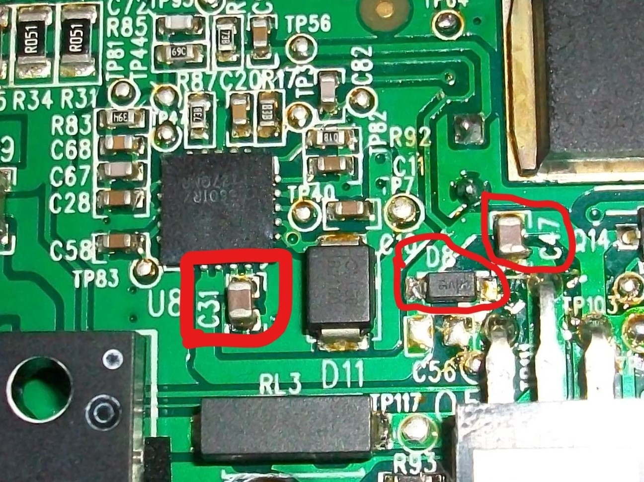
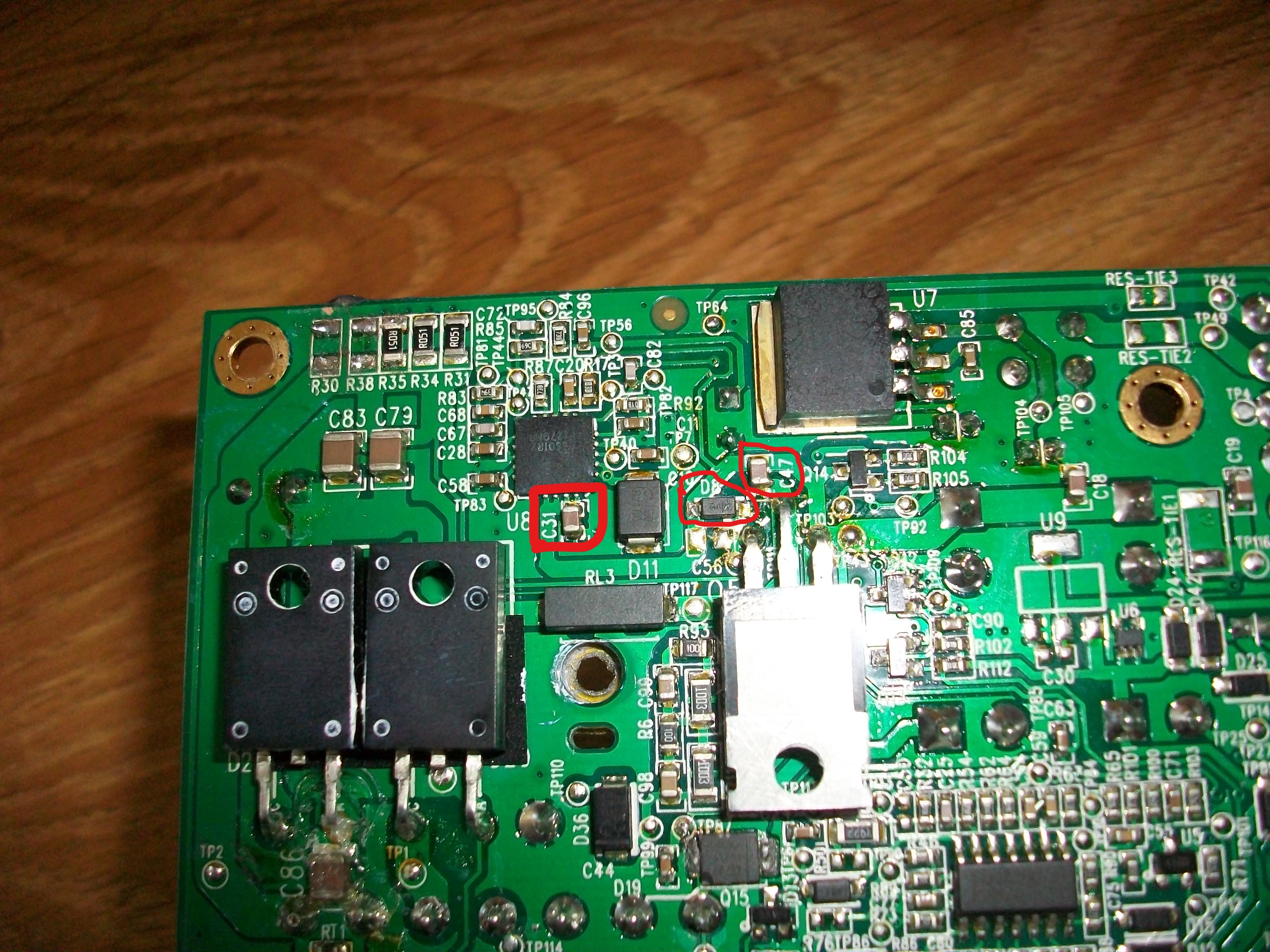
hlwww sir i want to know values on logitech z906 speakers power supply board plzzzzzz help me sir........
1.C31
2.C47
3.D8
-
-
hlwww sir i want to know values on logitech z906 speakers power supply board plzzzzzz help me sir....
1.C31
2.C47
3.D8
-
#66 Reply
Posted by
clwas1
on 08 Sep, 2017 00:06
-
I am new to this forum, but with the same problem, a blown Z906 power supply. In my case, it looks like the two fuses blew out along with the part RV1. The fuses are easy to replace, but does anyone know what a suitable replacement part would be for RV1? The letters on the attached blown out part are:
LF or IF
P150L18
1328
Thanks.
-
#67 Reply
Posted by
Rasz
on 08 Sep, 2017 21:39
-
it looks like the two fuses blew out along with the part RV1. The fuses are easy to replace, but does anyone know what a suitable replacement part would be for RV1?
its a MOV, those things dont blow on a whim, your supply is most likely shorted
-
-
hlwww sir i want to know values on logitech z906 speakers power supply board plzzzzzz help me sir........
1.C31
2.C47
3.D8
-
#69 Reply
Posted by
clwas1
on 08 Sep, 2017 22:46
-
Thanks. That maybe so, but I would like to replace the part if possible. I'll test everything before I switch on the power! What's an MOV and where can I get a replacement?
Thanks again.
-
#70 Reply
Posted by
clwas1
on 14 Sep, 2017 00:57
-
I wanted to post an update. I successfully replaced the two on board axial fuses + the MOV part (RV1). The system is now working again. The MOV actually did it's job when the power surge hit, but it was a pain to find and replace it. For anyone else. the link where I got it is here:
http://www.mouser.com/search/ProductDetail.aspx?r=576-V150LA10APThanks for the posts, it was helpful.
-
#71 Reply
Posted by
a3762341
on 03 Nov, 2017 12:49
-
Hey guys I'm just fix my z906 with other psu (48V 350w),and two AC to dc adapters(12v&5v),but i keep 5v back to original power board and connect the another connector with original power board that zeth9 said.
-
#72 Reply
Posted by
Costy91
on 04 Dec, 2017 16:06
-
Can I have a hand with my logitech z906. It just refuses to turn on. I opened it and you can see in the atached picture what happened. Is it fixable? Thank you
-
#73 Reply
Posted by
ciine
on 06 Dec, 2017 16:20
-
Thanks. That maybe so, but I would like to replace the part if possible. I'll test everything before I switch on the power! What's an MOV and where can I get a replacement?
Thanks again.
Download datasheet for the integrated and for the source and see what values are there.
-
#74 Reply
Posted by
Costy91
on 09 Jan, 2018 15:15
-
Where can I find the datasheet for the integrated and for the source?
-
#75 Reply
Posted by
Tejgla
on 18 Jan, 2018 10:35
-
Hello
I bought a mean well hlg-320h-48a supply and two power supplys to make 230ac to 12vdc (1,2A) and 5vdc (1A). From the amplifiler pcb I got 3.3v and soldered to +3,3v keep alive pin. Everything was fine about 20-25 minutes and after that the system shut down. I turned on again and I get an input 5 and aux error. I did a factory reset but 5 minutes later the system shut down again and I was unable to turn it on again. Hold the "effect" input 1 (6x) and center(3x) blinking.
Somebody can help me?
Thank you.
-
#76 Reply
Posted by
ciine
on 04 Mar, 2018 16:02
-
Voltages of 12, 5, and 3.3 v must be stabilized.
If they are made by the same source and have no stabilization when they increase the volume they fluctuate and is not correct
-
#77 Reply
Posted by
ruminaire
on 19 Mar, 2018 14:46
-
hello,
my rear channel output from subwoofer is having problem, the rear left strangely output -9.x volt, while rear right about +12v.
the front and center channel working normally and giving about +13v.
i open the subwoofer checking the power supply is good, 3.3v, 5v, 12v, 46v all okay when I measure them without connected to controller pcb board. as soon I connected psu to controller, all voltage reading is all wrong, I think I got short circuit somewhere.
i'm looking for sign of burn in component in controller pcb and not found anything strange, no burnt smell too.
then I found rear left positive output (red) is somehow short to ground, the negative output (black) is looking okay. what do you think is wrong here? rear right show no sign of shorting but it's not giving output sound too.
subwoofer and 3 channel front and center is still working by the way, it just rear channel is having problem. if this help, i got Logitech z906 from my friend and there was no center satellite. the problem start after 2 hour or so I put non Logitech z906 center and rear satellites for testing. it was fenda f6000 satellites. I don't know if that causing the amp fry or something because I use non Logitech satellites? is it possible?
the reason I use non Logitech rear speakers was for testing only as it's already in mounting, and I still didn't have mounting for Logitech one. that and for center speaker I couldn't help as this system I got come without it from my friend. and now I'm in regrets.
please help me, I got little knowledge for troubleshooting the circuit. also sorry for my English, I hope I make my question clear.
thanks.
-
#78 Reply
Posted by
a3762341
on 24 Mar, 2018 17:38
-
Hello
I bought a mean well hlg-320h-48a supply and two power supplys to make 230ac to 12vdc (1,2A) and 5vdc (1A). From the amplifiler pcb I got 3.3v and soldered to +3,3v keep alive pin. Everything was fine about 20-25 minutes and after that the system shut down. I turned on again and I get an input 5 and aux error. I did a factory reset but 5 minutes later the system shut down again and I was unable to turn it on again. Hold the "effect" input 1 (6x) and center(3x) blinking.
Somebody can help me?
Thank you.
Hey,you can use mean well's (48V 350W) supply for HV & GND on the main amp board. This is important. I just try this,and getting volume up for a long time without any problem.
-
#79 Reply
Posted by
ciine
on 09 May, 2018 16:24
-
hello,
my rear channel output from subwoofer is having problem, the rear left strangely output -9.x volt, while rear right about +12v.
the front and center channel working normally and giving about +13v.
i open the subwoofer checking the power supply is good, 3.3v, 5v, 12v, 46v all okay when I measure them without connected to controller pcb board. as soon I connected psu to controller, all voltage reading is all wrong, I think I got short circuit somewhere.
i'm looking for sign of burn in component in controller pcb and not found anything strange, no burnt smell too.
then I found rear left positive output (red) is somehow short to ground, the negative output (black) is looking okay. what do you think is wrong here? rear right show no sign of shorting but it's not giving output sound too.
subwoofer and 3 channel front and center is still working by the way, it just rear channel is having problem. if this help, i got Logitech z906 from my friend and there was no center satellite. the problem start after 2 hour or so I put non Logitech z906 center and rear satellites for testing. it was fenda f6000 satellites. I don't know if that causing the amp fry or something because I use non Logitech satellites? is it possible?
the reason I use non Logitech rear speakers was for testing only as it's already in mounting, and I still didn't have mounting for Logitech one. that and for center speaker I couldn't help as this system I got come without it from my friend. and now I'm in regrets.
please help me, I got little knowledge for troubleshooting the circuit. also sorry for my English, I hope I make my question clear.
thanks.
Check the contenders in the rejection filter, on the branch that has shortness at the table, surely one in short
-
#80 Reply
Posted by
scrhall
on 15 Nov, 2018 19:57
-
Hi, I just replaced my damaged power supply with a 48v 7A, with 3 step down to reach the 12v, 5v and 3.3v, everything works perfectly, but the power supply that I put consumes in standby approximately 15w and has a fan always running. The only thing I would like now, would be to turn on the system as soon as power is supplied to the power supply, that way I could control the power on and off from the socket.
Do you know somewhere on the motherboard where you can control the on and off?
https://photos.app.goo.gl/Bjyfycd1qyZmvKYXAhttps://photos.app.goo.gl/PWMrZRtTuWXksmNEA
-
#81 Reply
Posted by
ciine
on 18 Jan, 2019 18:05
-
Yes, at the moment the power play , the pw-on are 3, 3v
You use this 3,3v to command the fan ,or uses a thermistor to command the fan to engage at 50 degrees up
-
-
does the 30-50v hv+ connection require a regulator or just smoothed/filtered dc?
another poster built a linear psu by rewinding a secondary on a transformer sadly he didn't provide much info on how he built it
I have yet to find any info on the hv side some say 35v 10 amp others 48v 70v I would imagine there would be some kind of regulation on this portion
a switching psu is likely easier to buy but a linear psu is simpler to build from spare parts just to see if the amp is functional...
the 12v,5v regulators could likely be found in an old computer psu along with caps and other parts..
there is a possibility with any psu to have "noise" its a debatable topic as fords vs chevy debate will forever be debated...
you can also find dvd player psu produce 12v,5v via a linear psu
I did try to power the 5v and 12v from a separate psu but as ciine mentioned they have to be stable and this option dont work unless you could power both on at the same time and maintain the voltage
-
#83 Reply
Posted by
demail2006
on 03 Jan, 2020 18:21
-
My logitech z906 does not provide any sound from speakers, However input and output to headphones are working fine. I assume all other functions will also work fine.
I checked power supply and voltages. I get all voltage ok i.e. 2x 46 volts and 12 volt and 5 volt is dropping to 4.5 to 4 or below volts. I also have 3.3 volt standby voltage.
I even tried external 5v supply provided by 1 amp mobile charger, not working.
When I check voltage on speakers voltages are all over the place when tested for + and - it shows -7.5 volts some time on all speakers not connected and 0.0 on connected one and sometimes all shows +22, 5, 10 volts it's going all over the place

.
I checked main pcb 100v capacitors and they got 46v on them.
please help in fixing issues where should I start checking for faults.
-
#84 Reply
Posted by
tunk
on 03 Jan, 2020 18:44
-
I don't know what's the problem is, but I think you should start with setting your DMM to Vac.
And maybe feed it with e.g. a 1kHz sine signal.
Edit: if the headphone socket has a (logical) switch, check it.
-
#85 Reply
Posted by
demail2006
on 03 Jan, 2020 21:32
-
-
#86 Reply
Posted by
tunk
on 03 Jan, 2020 22:47
-
First, I don't really have a clue about this.
Do a web search for a 1kHz sine mp3-file and use that as input (from your phone?).
When you insert the headphone are the speakers muted? If so, there's some kind
of switch which does this, and if this is defect ...
-
#87 Reply
Posted by
BISZAK
on 27 Jan, 2021 20:13
-
Hi guys!
Can someone help me about some resistors, because my power supply burnt quite badly, and can't find any of these values
TP29;TP32;TP33;TP35;TP5?;TP97;TP48
these are near the big metal heating panel
Thank you!
-
#88 Reply
Posted by
Dinesh6252
on 14 Apr, 2021 04:47
-
Hello, just a quick question if someone can tell if i can supply 54V on HV+ line since, I have a 54+ that I want to use.
-
#89 Reply
Posted by
gue
on 17 Jul, 2021 18:40
-
Hello, I am new on this board and looked through this thread before but could not quit find my answer, even if someone already mentioned TP32.
I know how to solder but did next to nothing with electronics for quit some time.
I bought the z906 in 2011 and it went 'dead' today. After a very brief sound the lights went out and it smelled burnt. After stumbling across a few YouTube videos I opened the back of the subwoofer and compared to other damaged z906's mine looks 'not too bad' (maybe). Google brought me to this board and I read through this thread. I think the TP32 is broken as I measure "1" i.e., infinity, for resistance (it is a resistor right?), the TP29 has "a" measurement (I have a very cheap multimeter) so seems to be functional. I attached a picture of the backside where the burn marks a visible, other than that I could not (visually) find damaged parts. Be grateful for any tips/hints. Could it be just the TP32? If so, can someone post the specs on it.
-
-
tp are test points, not components.
See also the THT component in that area (opposite side)
-
#91 Reply
Posted by
gue
on 18 Jul, 2021 14:52
-
Ah, ok, TP stands for test point, thanks. On the other side is the component (picture) which looks a bit dark (burnt). I could not yet find other burnt components.
-
-
there are many nerds here ready to help you (not me

); however, you must provide more data, such as the screen printing of the burned component; do some measurement on the power board voltages, voltage arrives at the primary, for example, etc: you will see that someone will help you

-
-
Just a quick note about this resistor failure, it means one of the FETs on the heatsink have partially shorted. The originals are15N60C3 600 volt 15 amps. I think this goes along with the extra stress caused by some of the caps going bad on the output, 2 x 47uf 16 volts C39 C40 and 1 x 470uf 16volt C66, or it could be just one of those things that goes along with an input surge. You should proably also plan on replacing the MOV SL12 0006, I think its 10006 however the actual part has a missing piece, so the 1 is missing on mine. Also the 2 5R6 resistors may also be bad, i replaced them with 3 2 5R at 5W and 1 1R at 5 watts. Hope this helps others. Have a great day everyone, maybe hold the door open for someone if you can. If you can't play a sport, be one.
-
#94 Reply
Posted by
gue
on 27 Oct, 2021 08:40
-
Thanks for the reply. I gave it to a local repair shop. He managed to repair the power supply part but realized also the amp is damaged. At this point I chose to buy another sound system.
-
#95 Reply
Posted by
maxpayne
on 04 Nov, 2021 15:00
-
My Z906 power board died today. The speaker is not turning on anymore. I checked the power connector to the amp board and found, +46V, +12V and +5V, all are okay. However after disassembling the power board, I found the following components defective -
R79, R80, D42, D19 and U6(body marking 8AA). Could you help me to identify those components ? their body is damaged and I was unable to find the value.
Also one secondary transformer winding(marked in the picture) seems damaged as well. Can you tell my for which purpose the winding is used ? like for standby voltage supply ?
-
#96 Reply
Posted by
maj0r1337
on 26 Dec, 2021 22:04
-
hi guys, i also have trouble with my z906 but its not the power supply.
my speakers work fine and the controller also but my subwoofer is dead... not the speaker itself, he clicks when i power on the system. i think its the amp wich is defective. do you know where i should seharch on the board for that defective part? i cant find any damage to any components

best regards
-
#97 Reply
Posted by
maxpayne
on 27 Dec, 2021 04:25
-
My Z906 power board died today. The speaker is not turning on anymore. I checked the power connector to the amp board and found, +46V, +12V and +5V, all are okay. However after disassembling the power board, I found the following components defective -
R79, R80, D42, D19 and U6(body marking 8AA). Could you help me to identify those components ? their body is damaged and I was unable to find the value.
Also one secondary transformer winding(marked in the picture) seems damaged as well. Can you tell my for which purpose the winding is used ? like for standby voltage supply ?
Eventually I looked more into the board. found one of the transformer winding damaged. Also one zener diode, 2 schottkey diodes and one MOSFET (underneath the board, for switching the +45V line). The transformer winding was for generating the 3.3V keep alive voltage. As it was hard to repair a transformer, I just disregard the winding and generated the keep alive voltage from the +5V using the on board SOT 3.3V regulator.
The speaker is now back in life and running successfully from last couple of weeks..
-
#98 Reply
Posted by
KiKiHUN
on 02 Jan, 2022 18:24
-
-
#99 Reply
Posted by
Brzuszek
on 07 Jan, 2022 12:48
-
Hello, to start the amplifier, it needs 3.3v, 5v, 12v and 40v or 46v. How many watts must be
I want to use a power supply from china.
If there is anyone knows the values of the elements.
R8 R12 R95 R119 (The resistors are next to the C1 condenser)
C7 R24 Q16 (U1 system parts)
-
#100 Reply
Posted by
1Turk
on 09 May, 2022 22:17
-
what is power pin voltages ?
Can any write
-
#101 Reply
Posted by
Dinesh6252
on 07 Apr, 2023 01:05
-
Can anyone please tell me If a 54V power supply can be used on the hv+ since i have a 54V power supply? Thanks
-
#102 Reply
Posted by
Deeptarup
on 07 Nov, 2023 09:17
-
HI
I have z906 speaker which is giving an usual problem -- whenever I turn on the speaker its getting off instantly. Its happening for last few days..what could be the problem?