Yep RIFA X2. Well know flame throwers. Hit google images and search for "RIFA X2 explode".
Desolder it, clean the board up with IPA carefully and damage assess. If nothing is damaged, bring the supply up without it still installed and see if it works. That badly burned one is a write off.
I'd advise getting on the cleaning pretty quick as that goop sets like concrete after a couple of weeks.
Hi bd139
Please what do you mean with IPA, iso-propyl-alcohol?
Regards
Physicfan
What is the proactive treatment for this issue?
I have two of these on my bench that I fire up and use at least twice a week.
Proactive treatment is to replace them if they're old. The first visible signs of impending doom are small cracks developing in the transparent/translucent outer casing.
That's all you need to do. The cheap Chinese X2 rated ones are fine as replacements.
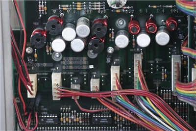
Images of parts of the DSA602:
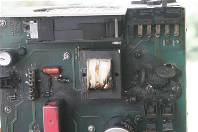
Defective component removed
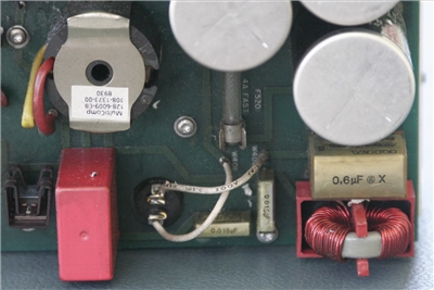
Second same component still intact
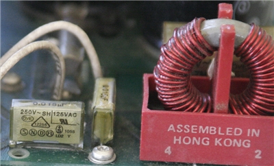
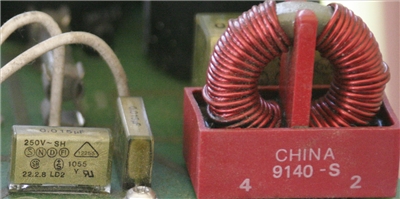
Small filters
Images of parts of the DSA602A:
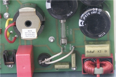
Second same component still intact
Small filters
I am looking forward to your comments
Not sure what the pictures are showing.. two different boards or boards from DSA602 and DSA602A?
Hello Johnny10
The pictures are showing views of boards from DSA602 (3) and DSA602A (2).
The pictures 1,2 and 3 of my last post show different views of the first power supply board of the DSA602.
The pictures 4 and 5 of my last post show the analog views of the same power supply board of the DSA602A.
For me it is remarkable that the same capacitors RIFA 0.6 uF X and RIFA 0.6 uF X2, both on the upper left of the boards, and also ONLY these, are fumed in these different oscilloscopes DSA 602 and DSA 602A, randomly?
I must also admit that this incident was my first encounter with this type of interference suppression capacitors.
Regards
Physikfan
I guess next week I will have to open these two beasts up and do some work.
Phew and they are beasts !
Check your HP kit as well. It's usually full of the flame throwing bastards!
For me it is remarkable that the same capacitors RIFA 0.6 uF X and RIFA 0.6 uF X2, both on the upper left of the boards, and also ONLY these, are fumed in these different oscilloscopes DSA 602 and DSA 602A, randomly?
Unfortunately, these RIFA caps are infamous for blowing up. The only random thing about them is which one will burst into flames next. Change them all before applying power again. Those small 0.015 look like RIFAs, too.
Hi Johnny10
If you will do the job next week
"I guess next week I will have to open these two beasts up and do some work."
please, could you post exactly the capacitors which you will use for the replacement.
You are planning to use new Y2 capacitors (two 0.6uF caps and two 0.015uF caps) for each of your DSA602´s of a certain brand or only high quality capacitors for high voltages around 1000V DC?
By the way, nice lab!
Regards
Physikfan
I am going to start looking for caps this week.
I went to my local surplus store but no x2 or Y caps in his stock.
Will have to look at suppliers.
So far they don't seem too expensive just that I am going to have to order through mail.
Will keep you informed.
Hi Johnny10 and all DSA602 and DSA602A owners
Please which DSA602 and DSA602A owner has already had its device open and
can tell me something about the wiring of this board just next to the power supply?
It is about the two-pole white plug, the third from the left bottom, with the two cables red and brown.
In my DSA602A it is present, in my DSA602 it is missing.
I wonder now, due to a lack of circuit diagram, whether it has to do with the power supply of the floppy disk drive in the DSA602A.
The DSA602A has one, the DSA602 has none.
Best regards
Physikfan
Hi bd139
Please what do you mean with IPA, iso-propyl-alcohol?
Regards
Physicfan
FYI, one other shorthand ---> DNA = denatured alcohol and not the stuff you provide to Ancestry.

No pictures of it but,
A customer was having an issue with a temp controller so they changed it out and wanted me to get calibration data on it. So they hand me a 120vac cut cord the controller and a picture of how it was wired. In the picture there was a black/white wire and everything thing else was red wiring.
I didn't even think and wired the 120vac black and white wires to the same wires as in the picture. Well, that was the normally closed relay and once I plugged into the outlet I tripped the breaker. Needless to say, the unit issues were put to rest since the unit was designed for 24 vdc and 120vac fried everything in it to power on.
Morale of the incident is when a customer tries to help, it never seems to end up good.
OK
So I opened the DSA602A !! Yikes that thing is heavy.
Sent Pic of control rectifier board on DSA602A
How did you get to RIFA chips?
Through back panel?
Hello Johnny10
To remove the power supply module from the DSA602A
the first step is to unscrew 14 screws at the back of the DSA602.
Before you completely remove this power supply module from the DSA602A, the second step is to disconnect the cables that you have shown in your image.
Your second DSA oscilloscope is also a DSA602A?
Regards
Physikfan
Second scope is DSA 602 no floppy drive
Hi Johnny10
Here are links containing access to DSA manuals:
http://w140.com/tekwiki/wiki/DSA600bee.mif.pg.gda.pl/ciasteczkowypotwor/Tek/DSA600-service.pdf
You have posted this nice picture of the DSA602A.
Please could you post also the analog picture of the DSA602?
Regards
Physikfan
OK I pulled out power supply.
Posted pics of both DSA units in previous post.... they look identical to me and the date markers are both from 1991.
Hello Johnny10
Have you finished the replacement of the X2 capacitors?
What kind of capacitors have you used finally?
Regards
Physikfan
No
I was working on getting the front keys on my datron 4000a working.
From another thread you can see that was all I needed to finish.
Success on that front.
Last 4 days prepping for Hurricane Irma.
I am on the East Coast... made it alright.
Next is DSA602A
Did you also change Y caps?
Back in the early days of personal computers (S-100 era) I acquired several very expensive 64K dynamic RAM boards since they were defective. Turns out the factory silk screened the component polarity incorrectly for the main tantalum cap on the minus voltage pwr supply. Plus symbol pointed to negative pwr rail and "-" pointed to ground.

They then went and stuffed the boards to match the indicated polarity. After a bit of usage they all when POOF! Magic smoke went out and the boards were sold for scrap. I installed new caps with the + lead to ground and "-" lead to the minus pwr rail and they all worked!

