-
Hello,
just needed to order a stash of different aluminium parts from a warehouse and thought adding some stuff for a diy yagi antenna construction, to make the shipping price less % of the whole order
I thought it would be kind of handy for me to make a 70cm band antenna (432MHz). So I have looked on different yagi calculators google could find withing a couple of searches. What I am quite surprised is that most of the calculators just throw lengths of the elements and their positions on the boom, but I think none of them did show any info about resulting impedance of the driven element.
Even the popular VK5DJ Yagi Calculator does not show any impedance info, rather just spits dimensions for a folded dipole with a 4:1 balun.
I find that strange for one part the impedance of the folded dipole (guessing) can't be 300 ohm anymore and second even if the dipole would somehow had 300 ohms, 4:1 balun would not cut it, not at least from a 50 ohm coax feedline (resulting in just 200 ohm at the dipole terminals). Or is this what is needed?
I am quite sure that the proximity of the parasitic elements inherently means the impedance of the driven element must be different from a "standard" free air impedance.
As a side note, due to the folded dipole being difficult to make precisely, wouldn't it be possible to use just a half-wave dipole? That one should have normally 73 ohm free air impedance, not sure how could one make a coaxial (or high power capable) balun from unbalanced 50 to balanced ~73 ohms.
In terms of antennas, I am quite a n00b, any hints really appreciated.
Thank you,
Y. -
After much deliberation and not needing a directional antenna I settled on a J-Pole (after member recommendations) for 315 MHz and 432 MHz will be just as easy to make and tune. Yagi just seemed a lot more work given I'm an RF noob too.
Looking back now just a SA and reflection bridge need be used to get a quite reasonable tune.
My battles and success are written up here:
https://www.eevblog.com/forum/rf-microwave/antenna-project-log/
Other antenna investigations:
https://www.eevblog.com/forum/rf-microwave/what-really-is-this-antenna/ -
This, from an expert in the field.
https://www.wa5vjb.com/yagi-pdf/cheapyagi.pdf
Key here is that while they might not squeeze the last fraction of a dB against a carefully tuned and machined antenna, they are very reproducible.
-
In fact it is easy
If your driven element is closed into loop then impedance is 300
if is open dipol type then impedance is 75 ohm and then you don't need asimetric baloon tranformer 4:1.
For 400mhz you can build double biquad antenna and u must use baloon.
-
No, it is not easy.
The dipole more than likely when near parasitic elements in a yagi configuration will have different impedance, than free air one.
Half-wave ("Open") dipole does have free space impedance of 73ohm (close to 75, sure), but still you can't connect that to a unbalanced coaxial 75 ohm cable, not to mention, that 75ohm is not the choice for transmitting, 50 is.
For open dipole with a 50ohm feed line, you would still need a 1.5 : 1 impedance balun (baloon is a different thing). 75 ohm unbalanced coaxial feed line would just get away with a 1:1 balun.
I know, there are many hacks and things that kind of work and kind of don't. I am not interested in those. I am not targeting "the simplest or weirdest antenna build", I just want to make a good quality yagi antenna. Not a slapped-together one, I have lot of those already.
-
Antenna impedance is a complex value. A dipole in free space at resonance have a typical impedance of 73+j42.5 Ohm.
Reactive part is due to nearfield coupling between dipole element parts and non ideal element.
A dipole can be impedance loaded by its nearfield in different ways such as placed near passive radiators and reflectors in a Yagi-Uda structure. This will affect measured impedance.
One effect of mismatch relative coaxial cable is that cable braid becomes a part of the radiating element. This is not necessary causing a lot of losses but will reduce directivity of antenna as a part of radiating element not is "in focus".
Antenna reactive part of impedance must also be handled for best antenna performance. If it is a narrow band antenna can reactive losses be compensated with discrete single component (capacitor/inductor). To further reduce antenna current along outside of coaxial braid can a 1:1 balun be used
and/or a quarter wave sleeve to create a reflect braid current to antenna dipole element
and/or ferrite material around coaxial cable with function to act as a RF resistor, burning effect else traveling outside coaxial braid. It is not optimal for antenna efficiency to burn neither TX or RX power but it will reduce negative impact on antenna radiation pattern and will make microphone less tingeling against lips, if HAM.
Also can it reduce received noise as coaxial cable will more easily pick up local noise along its way to ground then actual antenna, placed longer away from local noise sources.
For best result should antenna element in its actual environment of radiators and directors be tuned such that a not too critical frequency range is near to wished impedance and with low reactive impedance.
There are many variations how to do this, fine tuning dipole length and thickness, add end hats or bottom coils, integrate adjustable impedance adjustments of dipole in dipole structure. Gamma-match is a well known example of a such adjustable tuning.
Another kind of tuning is using small directors as impedance correcting element, placed near dipole element. Varying length and distance of a such element and both reactance and resistance be tuned.
An antenna tuned to 50+j0 Ohm can be connected to an coaxial cable with measured impedance of 50+j0 Ohm without need for a balun. It will not be any reflection along braid.
Cable impedance 50+j0 Ohm is measured if cable have this characteristic impedance and also radio TX/RX have same impedance. It have never happened for me. A radio is often said to be 50 Ohm but impedance is always everything except 50 Ohm and do often differ for RX respective TX. Assume at leasst 50% variation and with capacitive or inductive load.
A diy antenna can not be assumed to have expected impedance given from a simple online Yagi-calculator. Difference can be rather high.
If possible is impedance measurement of final built antenna to prefer to be able to correct any impedance mismatch.
Impedance mismatch at antenna can to a certain degree be measured with a simple VSWR meter. It can however only tell if there is a mismatch, not if it is a reactive or resistive loss or measure any value of impedance in terms of Ohm.
For more precise measurement is a VNA needed that can be impedance calibrated and set with correct timing delay at feeding point of dipole antenna.
A conclusion is that it is very easy to build antennas but very hard to make them work as assumed without measurement tools. Same problem as for building any else kind of RF circuit.
For RF filters and antennas is a VNA what a multimeter is for conventional LF electronics.
Not measure anything and it can still work good. Especially simple dipole antennas in free space will often work good enough in non critical circuits where last dB or absolute max distance is needed.
Even if it is a measured VSWR is as high as 3:1 will max coverage range only be reduced with 25%.
That is within reach for most diy untuned dipoles, with or without balun as long as antenna length is resonable correct and connections between antenna and cable is reasonable well done from RF view.
More critical antennas such as Yagis built for high directivity can easily loose expected performance with several dB even for minor design errors and to get last tenth of a dB in gain relative ideal calculated result will need days of fin-tuning using good measurement tools. -
This guy knows his stuff!
https://www.qsl.net/dk7zb/start1.htm
DK7ZB has a lot of practical designs on his website, apart from his antenna matching information.
By the way, the best way to irritate hams, & in fact most practical users of these antenna is to insist on calling them a "Yagi-Uda".
The common name for them is just "Yagi".
Sorry Mr Uda, but "them's the breaks"! -
>By the way, the best way to irritate hams, & in fact most practical users of these antenna is to insist on calling them a "Yagi-Uda".
It is an interesting opinion worth to comment to avoid that wrong information not is spread.
HAM people are often spreading less correct and oversimplified technical information. It is a reason for it. It is as hobby with a lot of spread in skills and no real need for knowledge required. That can be seen also in your link. No measured gain results for good reasons for any antenna, just ideal values from a simulation software. It is not that hard to measure transmission loss over a distance for an antenna and compare it with a dipole to get a clue about actual gain but nothing. Just a bunch hobby DIY instructions without any concrete measurements what to expect as final result.
And all these quarter wave coaxial transformers, why do they never occur in high quality professional antennas? Examples, antennas with qualified measured data.
A amateur designer of a lot of antenna ideas have maybe limited possibilities to provide data with professional quality, but at least something must he have done, some practical test and found that ideal values not is the best way to describe these antennas real performance? It is possible that there is some measured gain or efficiency measurements but I could not find anything at all.
There are some people that are both HAM and very skilled RF engineers or similar, but opposite is also common.
HAM's do for example often have problem with expressing basic things such as impedance. It is a complex value of resistance and reactance. It can be specified with real and imaginary values or as a vector with an angle in degrees or radians. Both resistance and reactance value must be measured for an antenna to be able to say anything about its impedance.
Measuring both these parameter do normally need a VNA, a often very expensive tool, without reach for hobby-use.
HAMs have therefore much omitted reactance part in its vocabulary as they anyway not is able to measure it. A simple VSWR meter (basically two diodes and a voltmeter) have been assumed best tuning tool and adding coils and capacitors for antenna tuning have been a trial and error process in lack of functional measurement tools.
It is however a bit interesting as previous very expensive tools now is within reach for amateurs, such as simple VNA's. Without requiring to much from the instrument can basic impedance measurements be done for a cost of $100.
Using a VNA in a correct way need a lot of knowledge and a lot of practice and many of these simpler VNA are limited in its functions but they do allows more people to practice and better learn how to use them.
Some will sooner or later find out that a such tool can be used for way more complex jobs then just measure VSWR. They will then for example find that impedance must be correctly expressed to be of any use in calculations or else will they not even be able to use result from the Smith chart which always is the basic impedance representation interface in a VNA.
A professional VNA is still rather expensive tool for good reasons. Besides a lot better measurements possibilities compared to tools for a few hundred bucks, is a such thing as a standard communication bus (IEEE-488) a basic need to be able to do measurement and communication that needs several instrument to be synchronized or as simple as synchronize with a turntable to measure an antenna 3D radiation pattern.
Just as important is that a VNA must be able to export its measured impedance values as S-parameters for further calculations or exchange data with other tools.
File format for simple exchange of data is therefor standardized (Touchstone).
Regarding your irritation that I did wrote "Yagi-Uda", can it be worth to check with the place where the antenna was invented.
The Yagi-Uda antenna array was invented at Tohoku university in Japan.
From university hompage: http://www.tohoku.ac.jp/en/research/index.html
Inventions born at Tohoku University include the KS and NKS steels, the Yagi-Uda antenna, fibre optics, and perpendicular magnetic recording.
Even worse at wikipedia: https://en.wikipedia.org/wiki/Yagi%E2%80%93Uda_antenna
The antenna was invented in 1926 by Shintaro Uda of Tohoku Imperial University, Japan, with a lesser role played by his colleague Hidetsugu Yagi.
Yagi published the first English-language reference for the antenna in a 1928 survey article on short wave research in Japan and it came to be associated with his name.
However, Yagi always acknowledged Uda's principal contribution to the design, and the proper name for the antenna is, as above, the Yagi–Uda antenna (or array).
Wikipedia is not completely correct. It was not invented 1926. The antenna was invented 1924 but development started 10 years before that and first patent application was filed in Japan 1925.
Yagi was a technical writer with less antenna knowledge and did not fully understand professor Uda's design. It can be seen in the US patent claims where he assumed that the shorter directors was related to that radiation pattern could be controlled by feeding higher frequencies to the shorter elements.
Nobody else did understand better so patent application was granted anyway.
Btw. I have been at Tohoku univ. during an antenna job so I have seen the original invented Yagi-Uda antenna which is saved and still in good shape.
You can do a lot to irritate your self less by learning correct naming of one of the most common and well known antenna types. If you prefer to say Yagi, skipping Uda, as many do, a bit rude against mr Uda maybe, but then we now you is a probably a HAM guy and we will still understand what kind of antenna you is thinking about. It is like if you are saying you is riding a Harley, we know what brand it is but you should be aware that you not is using the correct name.
Name of antenna is Yagi-Uda. Write Yagi if you prefer, just as Harley, we know what you mean. It is however a number of places you never can use it. In white papers and in patent applications for example. Such papers will be returned.
Blaming me for using "Yagi-Uda" with excuse "We HAM amateurs have decided to omit Uda as it not is commonly used by us in our untechnical and sloppy language and therefore should others neither do so, if they should avoid to irritate us", is that so clever to write?
-
Why so much hate? I have even tried to name the antenna correctly in the thread title.
I do not own any VNA (sure, pretty expensive instrument just for home toying), neither do I own any of the "simple china" ones everyone has hype over. I rather go and beg on places, where they have proper VNAs (up to 3GHz) to get a proper measurement.
So what do the professional antennas use, for impedance matching? I'd guess there is just an RF transformer (great, but not much for transmitting above a couple watts), or a spooled thin teflon coax to make the classical hairpin balun. I do not see many options past these two, that could be fitted in the small space available. -
No problem with your title, you can call it whatever you want as long as it is somewhat understandable what kind of antenna it is about, but if a unskilled beginner wrongly tells me what name to use for a classic antenna as he else will become irritated at me, is a bit too hilarious.
It can be pretty hard to design your own antenna and balun without proper tools. A Yagi-Uda is as complicated as an antenna can be. You want as beginner to build a precise designed ladder without tools in a dark room.
When using a VNA for designing antennas and baluns is VNA used as a design tool during whole development phase.
It is not something that you measure final result with as a kind of design confirmation.
It do not differ much from when designing a RF stage. Much tuning and design adjustments must be done based on measurements and not seldom must design take a few steps backward if intended goal not i reached. Knowing when to take these steps backward without tools is not possible.
Transformer exist for any power level. More then 100 kW is no problem but we keep the biggest coils in steel cages so that they not tries to knock down the house due to fast changes in power or antenna load. Such wild thing have actually happen.
Simplest is to design a dipole such that it is a perfect conjugate match relative radio impedance+antenna cable.
Then is no additional balancing element needed. Different kind of baluns can ensure better dipole balance and ferrite tubes can absorb power that is reflected.
A balun can improve impedance matching by transforming an impedance for better fit of antenna relative radio and it can make it harder for reflektions to reach cable braid at cost that it also affect antenn impedance.
An optimal effective antenna is conjugate matched but various baluns can be added to for example allow wider frequency range.
A Yagi antenna, what kind of balun to select is much a question about frequency, needed frequency range and type of dipole.
If you look at a professional antenna is balun part often self-described.
Some baluns can be more complex to understand.
Bicone antennas are designed to be very wideband. Antenna element must be designed to be impedance stable over a wide range at expected impedance. Same for balun part that must have wider frequency range then what a quarter wave transformer allows for.
A such balun can be seen here: http://www.gtemcell.com/wp-content/uploads/2012/02/DSC02335.jpg
This is a kind of balun very common in many kinds of Yagi-Uda antennas: https://encrypted-tbn0.gstatic.com/images?q=tbn:ANd9GcSmRjQyXCOF7QoPZSoxkaSDjUiuHHIOTOgrudU558EXZrwim9hM
Size differs with frequency. It is a cheap and simple design that is "good enough" and easy to design for conjugate match.
Also professional antennas us quarter wave transformer in several ways. This one is popular as it can be designed for very precise performance with aid of a simple tuning and because of that used as reference when measuring other antennas.: http://www.antennamagus.com/images/Newsletter2-1/Roberts-balun-large.png
Especially for higher frequencies can it be an advantage to design dipole and sometimes a whole Yagi-Uda antenna diretly at PCB: https://www.scribd.com/doc/73556375/Printed-Dipole-Antenna-With-Integrated-Balun
Main problem is if you want to design a high performing antenna without doing any measurements.
It will fail. Big.
I have designed antennas as professional for 30 years and I will fail if trying to design an Yagi-Uda without using tools.
A less experienced will fail bigger.
It is no absolute need for an VNA and it is in any case needed time to learn how to use it. It is very easy to measure but it is sometimes complex to measure correct.
VNA and measurement cable, when to notice or take action to avoid that they maybe will extend antenna ground plane resulting in false impedance readings, and what actions to do are such examples.
Measure with correct port forwarding is another common problem.
Without VNA do trial and error method remain. It is not nessary wrong and it is possible to reachgood result but it will take a factor 100 longer time comparing to use a VNA.
Design a simple oscillator with controlled impedance, sama as intended for antenna, and connect directly to antenna without cable or balun. Place a receiver 10 meters away in antenna directions and measure received signal level. Use a cable to extend signal reading so that you can read it while adjusting antenna.
Now tune extremly systematic. Paper and pen and tune in small steps. For impedance is it two unknown variables that should be adjusted for optimal result and it can take some time to get a feel for what is what.
When setting oscillator impedance without tools, do I use three resistors in similar fashion as when designing resistive attenuators. Allow for a 5-6 dB attenuation and your designed impedance.
That gives you a stable TX impedance without need for tool to measure impedance.
When antenna is final optimized , replace oscillator with intended balun and connect oscillator either directly at balun, now adjusted for assumed radio impedance+cable impedance, and tune the balun, if it is a tunable version or else can it be needed to continue to tune at the antenna.
If none of above seems doable for you, you want to design something fast and simple, with some directive gain, you accept that it will be few dB loss, then can a biquad be a possible solution. It is a very uncritical antenna where 8 dBi gain is reachable with a measuring tape as the only tool and basic skill in doing nice soldering and effective connections from RF view. If VSWR meter is used can antenna height adjust impedance. Adjust by brutal bending with you fingers. Is much tuning needed is it something wrong in the design. Find out and redo.
If you want to know more about innards of the antennas and antenna-shapes, do as I do, reverse engineer every antenna within reach and investigate why thing looks as they do. Most basic antenna shapes and baluns are technically described in books like https://www.wiley.com/en-us/Antenna+Theory%3A+Analysis+and+Design%2C+4th+Edition-p-9781118642061
That book is in antenna world the only book you need.
-
So what do the professional antennas use, for impedance matching? I'd guess there is just an RF transformer (great, but not much for transmitting above a couple watts), or a spooled thin teflon coax to make the classical hairpin balun. I do not see many options past these two, that could be fitted in the small space available.
Usually the matching is integrated into the antenna structure; for example a helical is often matched using a tapered copper foil strip at the feedpoint. For yagi-uda antennas the feedpoint impedance is usually near 1/4 the free space impedance of the dipole, so using a folded dipole as the driven element usually gives close to 50 ohms match already.
-
No problem with your title, you can call it whatever you want as long as it is somewhat understandable what kind of antenna it is about, but if a unskilled beginner wrongly tells me what name to use for a classic antenna as he else will become irritated at me, is a bit too hilarious.
I was in the Radio transmission business for more than 40 years before I retired, & have seen, & tested more antennas than I care to remember.
The antenna designed by Mr Yagi & Mr Uda was called a "Yagi" by every professional I ever met in that time.
We only have your own chest beating to vouch for your great antenna design skills.QuoteIt can be pretty hard to design your own antenna and balun without proper tools. A Yagi-Uda is as complicated as an antenna can be. You want as beginner to build a precise designed ladder without tools in a dark room.
Yet, thousands of Yagis are built by Amateurs & others every year.
Yes, maybe they aren't perfect, but they are good enough.QuoteWhen using a VNA for designing antennas and baluns is VNA used as a design tool during whole development phase.
It is not something that you measure final result with as a kind of design confirmation.
It do not differ much from when designing a RF stage. Much tuning and design adjustments must be done based on measurements and not seldom must design take a few steps backward if intended goal not i reached. Knowing when to take these steps backward without tools is not possible.
Transformer exist for any power level. More then 100 kW is no problem but we keep the biggest coils in steel cages so that they not tries to knock down the house due to fast changes in power or antenna load. Such wild thing have actually happen.
Steel cages will interact with any any RF coil.QuoteSimplest is to design a dipole such that it is a perfect conjugate match relative radio impedance+antenna cable.
Then is no additional balancing element needed. Different kind of baluns can ensure better dipole balance and ferrite tubes can absorb power that is reflected.
Twaddle!
Dipoles are balanced antennas, & coaxial cables are unbalanced feeders-- no amount of "conjugate matching" will change that.
A balun will convert between balanced & unbalanced --- that is where it gets its name from!Quote
A balun can improve impedance matching by transforming an impedance for better fit of antenna relative radio and it can make it harder for reflektions to reach cable braid at cost that it also affect antenn impedance.
An optimal effective antenna is conjugate matched but various baluns can be added to for example allow wider frequency range.
That is not the function of a balun!Quote
A Yagi antenna, what kind of balun to select is much a question about frequency, needed frequency range and type of dipole.
If you look at a professional antenna is balun part often self-described.
Some baluns can be more complex to understand.
Bicone antennas are designed to be very wideband. Antenna element must be designed to be impedance stable over a wide range at expected impedance. Same for balun part that must have wider frequency range then what a quarter wave transformer allows for.
Then the quarter wave transformers in TV transmission antenna arrays don"t work?QuoteA such balun can be seen here: [url]http://www.gtemcell.com/wp-content/uploads/2012/02/DSC02335.jpg[/url]
This is a kind of balun very common in many kinds of Yagi-Uda antennas: [url]https://encrypted-tbn0.gstatic.com/images?q=tbn:ANd9GcSmRjQyXCOF7QoPZSoxkaSDjUiuHHIOTOgrudU558EXZrwim9hM[/url]
Size differs with frequency. It is a cheap and simple design that is "good enough" and easy to design for conjugate match.
Also professional antennas us quarter wave transformer in several ways. This one is popular as it can be designed for very precise performance with aid of a simple tuning and because of that used as reference when measuring other antennas.: [url]http://www.antennamagus.com/images/Newsletter2-1/Roberts-balun-large.png[/url]
Especially for higher frequencies can it be an advantage to design dipole and sometimes a whole Yagi-Uda antenna diretly at PCB: [url]https://www.scribd.com/doc/73556375/Printed-Dipole-Antenna-With-Integrated-Balun[/url]
Main problem is if you want to design a high performing antenna without doing any measurements.
It will fail. Big.
I have designed antennas as professional for 30 years and I will fail if trying to design an Yagi-Uda without using tools.
A less experienced will fail bigger.
It is no absolute need for an VNA and it is in any case needed time to learn how to use it. It is very easy to measure but it is sometimes complex to measure correct.
VNA and measurement cable, when to notice or take action to avoid that they maybe will extend antenna ground plane resulting in false impedance readings, and what actions to do are such examples.
Measure with correct port forwarding is another common problem.
Without VNA do trial and error method remain. It is not nessary wrong and it is possible to reachgood result but it will take a factor 100 longer time comparing to use a VNA.
Design a simple oscillator with controlled impedance, sama as intended for antenna, and connect directly to antenna without cable or balun. Place a receiver 10 meters away in antenna directions and measure received signal level. Use a cable to extend signal reading so that you can read it while adjusting antenna.
Now tune extremly systematic. Paper and pen and tune in small steps. For impedance is it two unknown variables that should be adjusted for optimal result and it can take some time to get a feel for what is what.
When setting oscillator impedance without tools, do I use three resistors in similar fashion as when designing resistive attenuators. Allow for a 5-6 dB attenuation and your designed impedance.
That gives you a stable TX impedance without need for tool to measure impedance.
When antenna is final optimized , replace oscillator with intended balun and connect oscillator either directly at balun, now adjusted for assumed radio impedance+cable impedance, and tune the balun, if it is a tunable version or else can it be needed to continue to tune at the antenna.
If none of above seems doable for you, you want to design something fast and simple, with some directive gain, you accept that it will be few dB loss, then can a biquad be a possible solution. It is a very uncritical antenna where 8 dBi gain is reachable with a measuring tape as the only tool and basic skill in doing nice soldering and effective connections from RF view. If VSWR meter is used can antenna height adjust impedance. Adjust by brutal bending with you fingers. Is much tuning needed is it something wrong in the design. Find out and redo.
If you want to know more about innards of the antennas and antenna-shapes, do as I do, reverse engineer every antenna within reach and investigate why thing looks as they do. Most basic antenna shapes and baluns are technically described in books like [url]https://www.wiley.com/en-us/Antenna+Theory%3A+Analysis+and+Design%2C+4th+Edition-p-9781118642061[/url]
That book is in antenna world the only book you need. -
Quote
I was in the Radio transmission business for more than 40 years before I retired, & have seen, & tested more antennas than I care to remember.
The antenna designed by Mr Yagi & Mr Uda was called a "Yagi" by every professional I ever met in that time.
You have never read or written a white paper or a patent application related to antennas where this antenna is referrred?
Basic antenna bible, Balani Antenna theory, should be known by any professional as a minimum. Open it at chapter 10 and read.QuoteWe only have your own chest beating to vouch for your great antenna design skills.
No meaning to boast but I do not like your way doing insinuations about me.
For that reason have you have got PM about my patent portfolio for a wide range of antennas. My antenna design software is used in most bigger RF labs developing cell phone antennas or other embedded antenna. You will get a link to its homepage.
Do expect similar portfolio from you. Fair deal?QuoteSteel cages will interact with any any RF coil.
I am sure you have seen them, common in old shortwave stations, always in steel cages and sometimes with motorized tuning equipment mounted at the cage. Commonly known as antenna loading coil and often used at bigger commercial shortwave transmitter stations. Typical 100 mm solid copper wire winded as a coil. Example of a such old coil under delivery Today would that amount of copper cost just as much as all other equipment together.
These coils could cause a lot of mechanical power if heavy modulated. We are talking about 100kW magnetic loss only in coil. A such transmitter was always ramped up slowly to not destroy its coils.QuoteTwaddle!
Long experience and not knowing this kind of stuff?
Dipoles are balanced antennas, & coaxial cables are unbalanced feeders-- no amount of "conjugate matching" will change that.
A simplified example: A resistor is a balanced load, comparable with a well balanced dipole.
Assume you have a ideal coaxial able with characteristic impedance 50 Ohm, feed by a 50 Ohm radio and solder a 50 Ohm resistor at coaxial cable end using real short wires.
Will it be any reflections along cable braid? No it is not possible. It is much comparable with adding a termination load at coaxial cable.
Will it be any practical change how resistor and cable current is flowing if placing a ideal 1:1 balun between cable and resistor? No.
Can the resistor be replaced with any else 50 Ohm resistive load, such as a well matched dipole without causing any changes in load sensed by coaxial cable? Yes.
Will it be any unbalanced current causing reflections along cable braid? Still no.
You get it now?QuoteThat is not the function of a balun!
In most of today very compact electronic and embedded antennas do we seldom have the luxury to avoid this.
<boastmode on>One of my currently most selling antennas (~10k/month) is the groundplane part of the balun for low frequencies while it is a conventional ground for the upper frequencies.
Works very well and is class leading, markets best performing antenna in its class. It is an antenna for IoT in need of maximal coverage whatever frequency.<boastmode off>
You will get a link in PM to that antenna as well so that you not insinuate that it is made up.QuoteThen the quarter wave transformers in TV transmission antenna arrays don"t work?
That belongs almost to way too basic knowing to not even comment if you have long experience about antennas.
They do work to some degree. For UHF band is a such transformer typical centered at 630MHz and must then cover additional +/- 25% (470-800MHz). It will create a rather big phase error at band edges and poor balance as a quarter wave at 630MHz not any longer is a quarter-wave at bandedges. Count with some losses and a balun up to 90 degrees out of phase. Good enough to sell to consumers.
UHF Yagi-Uda for improved TV reception have been sold in two versions. One for lower half of UHF band and one for upper UHF band.
Upper frequency part is in many countries now reserved for cell phones and UHF for TV have become more narrow.
A real wide band antenna usable over a frequency decade such as some bicone antennas or logperiodic antennas can not use a quarterwave transformer as already at 2*f0 have it become a halfwave transformer which not is usable. -
I've been ham for last 40+ years, and I made my share of antennas.
When ever you see calculations, whether the length of element or impedance, they are based on it being in free space. Simplistic calculations also assume element/wires are infinitely thin and has zero resistance. In reality, none of these assumptions are true. Reasonably created and erected half wave dipole will present close to 50 ohm impedance rather than theoretical 73 ohms.
Multi-element antennas such as Yagi-Uda or Cubical Quad are even more complex. There is boom, mast, nearby element, thickness of element, parasitic capacitance, tower, building, ground, etc, etc, etc, will make non-negligible impact. End result is, you either accept imperfect but good enough solution or spend days or weeks simulating, adjusting, and testing.
Feed point impedance usually gets lower as more element are added. That's why you see folded dipole design often. It's easier to match.
We can argue this until EEVBLOG crashes but end result is always the same. Make it and test it. That's all you can do. -
A simplified example: A resistor is a balanced load, comparable with a well balanced dipole.
Assume you have a ideal coaxial able with characteristic impedance 50 Ohm, feed by a 50 Ohm radio and solder a 50 Ohm resistor at coaxial cable end using real short wires.
Will it be any reflections along cable braid? No it is not possible. It is much comparable with adding a termination load at coaxial cable.
Will it be any practical change how resistor and cable current is flowing if placing a ideal 1:1 balun between cable and resistor? No.
Can the resistor be replaced with any else 50 Ohm resistive load, such as a well matched dipole without causing any changes in load sensed by coaxial cable? Yes.
Will it be any unbalanced current causing reflections along cable braid? Still no.
You get it now?
Excuse me sir,
The differential impedance may be matched, you are quite correct. (We can assume a dipole cut and loaded for 50 ohms resistive at resonance, for sake of argument.)
But what of the impedance from the element to ground (or to space at infinity, if nothing else)? It is not infinite, is it?
If it be finite, then is there not some impedance from ground to each terminal of the antenna? And if the antenna and its surroundings are symmetrical, then would those impedances not be equal?
Therefore, you would have an equivalent circuit of a Thevenin voltage source (the transmitter via coax), connected to the antenna, to ground?
And, you would have a nonzero voltage on that voltage source's common terminal, no?
So if the voltage source is not a balanced line (twisted pair, twin lead, etc.), if it is unbalanced such as coax, there would be a common mode wave (shield currents), no?
Tim -
Hi Tim,
I can not fully understand what you is thinking about but most of my antennas are embedded antennas +GHz range.
When handheld do Earth ground not exist in my calculations as earth is in infinite distance of antenna nearfield.
Situation is a bit different for many radio-amateurs placing horizontal or vertical dipole antennas in a garden with its height at a fraction of actual wavelength above ground.
That reminds me a bit about situation in picture below.
It shows a dipole feed by an unbalanced coaxial cable.
If height above ground been high had it been perfectly fine to feed this balanced dipole with an unbalanced coaxial cable.
Due to near and uneven distance from ground is dipole in picture not any longer in balance. Common mode current will flow outside of cable shield.
It is shown in right picture that a common mode choke will reduce the problem.
I have borrowed below picture and some text from: https://interferencetechnology.com/antenna-fundamentals/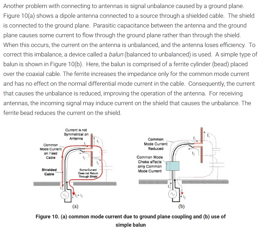
I have a bit of similar problem for some of my antennas, that a temporary measurement coaxial cable must leave antenna/PCB plane perpendicular to antenna orientation in a "cold" location of PCB to not affect existing antennas and and its internal feed.
This is an example of how a measurement cable is routed in an early stage of development of an cellphone antenna:
Did these picture somewhat address what you was thinking about? -
Quote
I was in the Radio transmission business for more than 40 years before I retired, & have seen, & tested more antennas than I care to remember.
The antenna designed by Mr Yagi & Mr Uda was called a "Yagi" by every professional I ever met in that time.
You have never read or written a white paper or a patent application related to antennas where this antenna is referrred?
Basic antenna bible, Balani Antenna theory, should be known by any professional as a minimum. Open it at chapter 10 and read.
I have read such things, but I was really referring to general usage amongst EEs, Technicians, etc working with such antennas.
Mr Uda definitely was greatly wronged by the widespread dropping of his name by people referring to his antenna.
This is not uncommon, however, do you always refer to "Eccles-Jordan flip-flops", or do you, like most of us, just say "flip-flops"?
How about "Foster Seeley discriminators", or when referring to the ionosphere, the "Oliver-Heaviside layer"?Quote
No, I'm not going down that rabbit hole!QuoteWe only have your own chest beating to vouch for your great antenna design skills.
No meaning to boast but I do not like your way doing insinuations about me.
For that reason have you have got PM about my patent portfolio for a wide range of antennas. My antenna design software is used in most bigger RF labs developing cell phone antennas or other embedded antenna. You will get a link to its homepage.
Do expect similar portfolio from you. Fair deal?
You can no doubt bash me with all your patents, but the fact remains, that your postings on this thread do include errors in a lot of areas where I do have knowledge.QuoteQuoteSteel cages will interact with any any RF coil.
I am sure you have seen them, common in old shortwave stations, always in steel cages and sometimes with motorized tuning equipment mounted at the cage. Commonly known as antenna loading coil and often used at bigger commercial shortwave transmitter stations. Typical 100 mm solid copper wire winded as a coil. Example of a such old coil under delivery Today would that amount of copper cost just as much as all other equipment together.
These coils could cause a lot of mechanical power if heavy modulated. We are talking about 100kW magnetic loss only in coil. A such transmitter was always ramped up slowly to not destroy its coils.
I think you will find that most such coils are not made from solid copper wire, but from hollow copper tubing.
The coil in the pix you linked to is one of that type.
The frame around such coils is certainly designed to hold the coil rigidly.
Even without your "mechanical power", the coil could collapse under its own weight.
Also, on all such coils I have seen, that frame is made from non metallic materials, due to the high losses inherent with having "shorted turns" linked to the inductor.
I have direct experience with MF & HF transmitters & coupling units up to 50kW, &, in no case were they "ramped up" slowly.
I have also visited a 250kW HF site when they were turning the Tx on, & again, they were not "ramped up".Quote
If you unbalance a balanced antenna, it tends to look as if it is a top loaded vertical operated against earth, with outer shield of the coax making up most of the antenna.QuoteTwaddle!
Dipoles are balanced antennas, & coaxial cables are unbalanced feeders-- no amount of "conjugate matching" will change that.
Long experience and not knowing this kind of stuff?
A simplified example: A resistor is a balanced load, comparable with a well balanced dipole.
Assume you have a ideal coaxial able with characteristic impedance 50 Ohm, feed by a 50 Ohm radio and solder a 50 Ohm resistor at coaxial cable end using real short wires.
Will it be any reflections along cable braid? No it is not possible. It is much comparable with adding a termination load at coaxial cable.
Will it be any practical change how resistor and cable current is flowing if placing a ideal 1:1 balun between cable and resistor? No.
Can the resistor be replaced with any else 50 Ohm resistive load, such as a well matched dipole without causing any changes in load sensed by coaxial cable? Yes.
Will it be any unbalanced current causing reflections along cable braid? Still no.
You get it now?
This "phantom " antenna can radiate , interfering with the desired radiation, adversely changing the radiation pattern.
Most of the time at HF, Amateurs get away without using baluns, but in the worst case scenario may have
what they refernto as "RF in the shack".
This is in no way incompatible with the cable being correctly matched.QuoteQuoteThat is not the function of a balun!
In most of today very compact electronic and embedded antennas do we seldom have the luxury to avoid this.
<boastmode on>One of my currently most selling antennas (~10k/month) is the groundplane part of the balun for low frequencies while it is a conventional ground for the upper frequencies.
Works very well and is class leading, markets best performing antenna in its class. It is an antenna for IoT in need of maximal coverage whatever frequency.<boastmode off>
You will get a link in PM to that antenna as well so that you not insinuate that it is made up.QuoteThen the quarter wave transformers in TV transmission antenna arrays don"t work?
That belongs almost to way too basic knowing to not even comment if you have long experience about antennas.
They do work to some degree. For UHF band is a such transformer typical centered at 630MHz and must then cover additional +/- 25% (470-800MHz). It will create a rather big phase error at band edges and poor balance as a quarter wave at 630MHz not any longer is a quarter-wave at bandedges. Count with some losses and a balun up to 90 degrees out of phase. Good enough to sell to consumers.
What part of "TV transmission" don't you understand?
This refers to the massive antenna arrays on top of towers, on top of mountains.
Most of my experience has been with antennas designed to cover a single VHF or UHF TV channel, so the errors are fairly minimal.
These certainly use quarter wave transformers.
Wideband antennas have become more common in recent years, but do not normally cover such a wide bandwidth as you quote.
They are certainly not simple devices, & I have no "in depth" experience of them.Quote
UHF Yagi-Uda for improved TV reception have been sold in two versions. One for lower half of UHF band and one for upper UHF band.
In Australia, such receiving antennas commonly include elements for both bands on the one boom.
Yes, they interact, but the designers allow for this.QuoteUpper frequency part is in many countries now reserved for cell phones and UHF for TV have become more narrow.
A real wide band antenna usable over a frequency decade such as some bicone antennas or logperiodic antennas can not use a quarterwave transformer as already at 2*f0 have it become a halfwave transformer which not is usable.
Indeed, but the OP was asking about "Yagi-Uda" antennas, which are not wideband antennas.
Bicone antennas do not offer the amount of gain available from parasitic antennas, & log periodic antennas, although high gain, are both complex & large. -
Why so much hate? I have even tried to name the antenna correctly in the thread title.
I do not own any VNA (sure, pretty expensive instrument just for home toying), neither do I own any of the "simple china" ones everyone has hype over. I rather go and beg on places, where they have proper VNAs (up to 3GHz) to get a proper measurement.
So what do the professional antennas use, for impedance matching? I'd guess there is just an RF transformer (great, but not much for transmitting above a couple watts), or a spooled thin teflon coax to make the classical hairpin balun. I do not see many options past these two, that could be fitted in the small space available.
If you don't have a VNA, even more so I recommend Kent Britain's Cheap Yagi paper that I mentioned before https://www.wa5vjb.com/yagi-pdf/cheapyagi.pdf
The key point of these is that they are easily reproducible: if you've ever done much antenna work, much of the prescribed publications seem to be based on unicorn technology that might have worked once, but are not reproducible because some detail or other is missing.
These deal with both the matching and balun aspects discussed above. The driven element is integrated with the balun. It's based on his own patent here, and it's worth a read: Yagi antenna having matching coaxial cable and driven element impedances
I don't know if you've ever played with NEC or its derivatives, but if you have you'll know it's the epitome of the squidgy balloon analogy. You make a small change to optimise for, say, front-to-back ratio, and out will pop a side lobe, the gain drops, the bandwidth changes, and/or the impedance sails off into the blue yonder. -
you must look here:
http://www.iw5edi.com/technical-articles/6-element-for-432-mhz -
you must look here:
http://www.iw5edi.com/technical-articles/6-element-for-432-mhz
Gamma match: b!tches to tune!
-
A good mix of theory and practical advice can be found here at DG7YBN's wonderful site:
http://dg7ybn.de/Building/Building.htm
-
I think it is fair to say I've done what you could call antenna design in the past. Can't really chip in on the entire balun-business since the near field of my antennas is expressed in millimeters. I've never been able to use a VNA as a design tool since I can't just go about changing my antenna designs by hand, they are too small for that. As a result, I have noticed I have a different approach to many things than most - not better, not worse, just different.
Of course, near-field and far-field are just things we like to come up with to make our life easier. There is no hard line where it suddenly stops influencing the antenna - I have seen this in cases where metal objects hundreds or even thousands of wavelengths away from the antenna impacted antenna impedance to the point where the circuit performance was influenced significantly.
As to the matching: The way I have understood matching of dipole antennas and similar is always as a resonating element - when you think about it, you have a current wave that is 0 at the ends and maximum in the middle, and a voltage standing wave that is opposite - the voltage is highest at the ends and lowest (well, 0) in the middle.
You can then just choose how far along you end up feeding this entire structure. The V/I ratio at that location determines the impedance.
Needless to say, this is a simplification, and parasitic elements, the fact that you can't have ideal standing waves, and the fact that your antenna is never exactly the right length, all cause errors here. And yes, if you feed a dipole exactly in the middle, you will indeed see that magic impedance people keep talking about - but if you shift those feed points a bit, you will influence that impedance, and you can actually play around with it to better match your transmission line (this is what inserts are doing in the case of microstrip-fed patch antennas)
I think in the case of a yagi, since the elements should all be designed in such a way to co-resonate to some extent, you don't see them in the impedance that much. Hence the impedance is still similar to that of a dipole. (could be totally wrong, I have never designed a yagi)The key point of these is that they are easily reproducible: if you've ever done much antenna work, much of the prescribed publications seem to be based on unicorn technology that might have worked once, but are not reproducible because some detail or other is missing.
Not to mention all of the 'we added a slot here and 'tada' better performance. Oh but we forgot to mention we kinda let our EM solver optimize over 12 different parameters for 2 weeks to get this and we have no clue why it works but here is a plot of the currents on the ground because I guess everyone puts them in their papers so we probably should too!'
Regarding the feelings expressed by some here towards HAMs: I can understand where you are coming from. This is the same with all somewhat technical hobbies: Unfortunatly a lot of people are not experts, and just do stuff because they are told or because that is how it has always been done, and use poor terminology, etc. I have learned to somewhat accept this, and instead of fighting it, trying to help and perhaps explain more clearly. The only point when I really can't restrain myself is when HAMs (or makers or whatever) talk like they are all engineering experts and know everything or worse still make statements like 'why go to school when I can make these things at home'. There is a few of those I see here on the forum and on youtube etc, and to be blunt, I usually just think: "well if it is so easy and you don't need school, howcome you are the technician and I'm the one designing the things you are a technician for?"
Just to be clear: I have a great amount of respect for the practical and hands-on knowledge technicians and similar have. It just bothers me that sometimes, they don't seem to respect the theoretical and design knowledge I have spent years building up.
kinda don't know where I was going with this but whatever, do with it as you please. -
I think it is fair to say I've done what you could call antenna design in the past. Can't really chip in on the entire balun-business since the near field of my antennas is expressed in millimeters. I've never been able to use a VNA as a design tool since I can't just go about changing my antenna designs by hand, they are too small for that. As a result, I have noticed I have a different approach to many things than most - not better, not worse, just different.
You are wrong, the impedance of the yagi driven element is affected by the presence of the other elements, & by the spacing of such elements both away from the DE & between themselves.
Of course, near-field and far-field are just things we like to come up with to make our life easier. There is no hard line where it suddenly stops influencing the antenna - I have seen this in cases where metal objects hundreds or even thousands of wavelengths away from the antenna impacted antenna impedance to the point where the circuit performance was influenced significantly.
As to the matching: The way I have understood matching of dipole antennas and similar is always as a resonating element - when you think about it, you have a current wave that is 0 at the ends and maximum in the middle, and a voltage standing wave that is opposite - the voltage is highest at the ends and lowest (well, 0) in the middle.
You can then just choose how far along you end up feeding this entire structure. The V/I ratio at that location determines the impedance.
Needless to say, this is a simplification, and parasitic elements, the fact that you can't have ideal standing waves, and the fact that your antenna is never exactly the right length, all cause errors here. And yes, if you feed a dipole exactly in the middle, you will indeed see that magic impedance people keep talking about - but if you shift those feed points a bit, you will influence that impedance, and you can actually play around with it to better match your transmission line (this is what inserts are doing in the case of microstrip-fed patch antennas)
I think in the case of a yagi, since the elements should all be designed in such a way to co-resonate to some extent, you don't see them in the impedance that much. Hence the impedance is still similar to that of a dipole. (could be totally wrong, I have never designed a yagi)
In the website I linked, https://www.qsl.net/dk7zb/6m/212.htm
DE impedances of 12.5, 18.0 & 28.0 Ohms are referred to, (with matching methods described)---all a far cry from approx 73.0 Ohms for a dipole in free space.
Most simple dipoles are not "in free space", the closer they approach the Earth's surface, the more the impedane drops, so that the wire dipoles commonly used by Hams are often a good match for 50.0 Ohm coaxial cable.
If the dipole impedance is affected in this way, is it surprising that parasitic elements small fractions of a wavelength away from the DE of a yagi will affect that element?Quote
Many Hams are Engineers with similar qualifications to yourself, & with extensive experience with the design, testing & construction of antennas.The key point of these is that they are easily reproducible: if you've ever done much antenna work, much of the prescribed publications seem to be based on unicorn technology that might have worked once, but are not reproducible because some detail or other is missing.
Not to mention all of the 'we added a slot here and 'tada' better performance. Oh but we forgot to mention we kinda let our EM solver optimize over 12 different parameters for 2 weeks to get this and we have no clue why it works but here is a plot of the currents on the ground because I guess everyone puts them in their papers so we probably should too!'
Regarding the feelings expressed by some here towards HAMs: I can understand where you are coming from. This is the same with all somewhat technical hobbies: Unfortunatly a lot of people are not experts, and just do stuff because they are told or because that is how it has always been done, and use poor terminology, etc. I have learned to somewhat accept this, and instead of fighting it, trying to help and perhaps explain more clearly. The only point when I really can't restrain myself is when HAMs (or makers or whatever) talk like they are all engineering experts
Many of the rest of us have worked with antennas of various kinds over decades, so maybe, just maybe, do know a little about such devices.Quoteand know everything or worse still make statements like 'why go to school when I can make these things at home'. There is a few of those I see here on the forum and on youtube etc, and to be blunt, I usually just think: "well if it is so easy and you don't need school, howcome you are the technician and I'm the one designing the things you are a technician for?"
Where do you get the idea that technicians don't go to school?
Without a reasonable amount of technical knowedge, we would not be able to do our job!
I very much doubt I have ever worked on anything you designed, but I have encountered many silly design blunders on the part of EEs, ones which with a few minutes of reflection, or perusing other EE's designs would have been avoided.
Techs do see a lot of other designs, & can usually have a good handle on which designs are poor, & which aren't.QuoteJust to be clear: I have a great amount of respect for the practical and hands-on knowledge technicians and similar have. It just bothers me that sometimes, they don't seem to respect the theoretical and design knowledge I have spent years building up.
I, similarly, have a great deal of respect for EEs, but expect of them a higher level of knowledge, & will "call them out" on it when they are demonstrably wrong on factual matters.Quote
kinda don't know where I was going with this but whatever, do with it as you please. -
You are wrong, the impedance of the yagi driven element is affected by the presence of the other elements, & by the spacing of such elements both away from the DE & between themselves.
In the website I linked, https://www.qsl.net/dk7zb/6m/212.htm
DE impedances of 12.5, 18.0 & 28.0 Ohms are referred to, (with matching methods described)---all a far cry from approx 73.0 Ohms for a dipole in free space.
Most simple dipoles are not "in free space", the closer they approach the Earth's surface, the more the impedane drops, so that the wire dipoles commonly used by Hams are often a good match for 50.0 Ohm coaxial cable.
If the dipole impedance is affected in this way, is it surprising that parasitic elements small fractions of a wavelength away from the DE of a yagi will affect that element?
The reason I was thinking the impedance change might not be very large is because often the coupled elements resonating at the same frequency can have that effect, and I thought that the distance between elemeents was also a fixed fraction of a wavelength (as I said - not designed any yagi-uda antennas myself). Having worked on things like frequency-selective surfaces and meta-materials, I've kinda gotten used to metals just 'dissapearing' at your target frequency and things behaving like they are not there.
And the antennas and dipoles I do design are electrically far from the earth so their impedance is not influenced by it. I wasn't aware that the impedance changed that much at HAM frequencies and sizes, learned something new today.QuoteQuoteRegarding the feelings expressed by some here towards HAMs: I can understand where you are coming from. This is the same with all somewhat technical hobbies: Unfortunatly a lot of people are not experts, and just do stuff because they are told or because that is how it has always been done, and use poor terminology, etc. I have learned to somewhat accept this, and instead of fighting it, trying to help and perhaps explain more clearly. The only point when I really can't restrain myself is when HAMs (or makers or whatever) talk like they are all engineering experts
Many Hams are Engineers with similar qualifications to yourself, & with extensive experience with the design, testing & construction of antennas.
Many of the rest of us have worked with antennas of various kinds over decades, so maybe, just maybe, do know a little about such devices.
I never said that none of them have similar qualifications. I said that there a lot that are not experts. Perhaps, not being a HAM myself, I have a very skewed perception of what ratio of HAMs are not experts, because I only see those I run into online on certain forums etc.QuoteQuote
Where do you get the idea that technicians don't go to school?
and know everything or worse still make statements like 'why go to school when I can make these things at home'. There is a few of those I see here on the forum and on youtube etc, and to be blunt, I usually just think: "well if it is so easy and you don't need school, howcome you are the technician and I'm the one designing the things you are a technician for?"
Without a reasonable amount of technical knowedge, we would not be able to do our job!
Ofcourse, I did not literally mean they never go to school. Perhaps this is also a matter of interpretation of the term 'technician' in different locations, but where I live, a technician is usually someone with a bachelors degree, where the degree focused little on theoretical background. The technicians I have run into (again, likely not a fair sample of the population) tend to say that all that theory taught in schools is useless, and that engineers don't know what they are doing, etc.
I'm not going to say all engineers are experts and know better, because I know a lot that are not, me included (as I skillfully demonstrated with my yagi example). I am fascinated when I work with people on the metalworking floors with all the practical insights they bring to the table.QuoteI very much doubt I have ever worked on anything you designed, but I have encountered many silly design blunders on the part of EEs, ones which with a few minutes of reflection, or perusing other EE's designs would have been avoided.
Techs do see a lot of other designs, & can usually have a good handle on which designs are poor, & which aren't.
Indeed, it would be highly unlikely you worked on anything I designed - I can count on my fingers the amount of people who have. And I agree with you - techs can bring a lot of insight and knowledge to the table, something which often is lacking in the design process.QuoteQuoteJust to be clear: I have a great amount of respect for the practical and hands-on knowledge technicians and similar have. It just bothers me that sometimes, they don't seem to respect the theoretical and design knowledge I have spent years building up.
I, similarly, have a great deal of respect for EEs, but expect of them a higher level of knowledge, & will "call them out" on it when they are demonstrably wrong on factual matters.
As you did above, for which I thank you.
EDIT- fixed quotes because dealing with so many /quote and quote things gets messy fast.