-
Hi everybody,
I recently purchased an inexpensive EIP 545B on eb (one of the devices recently sold from Israel).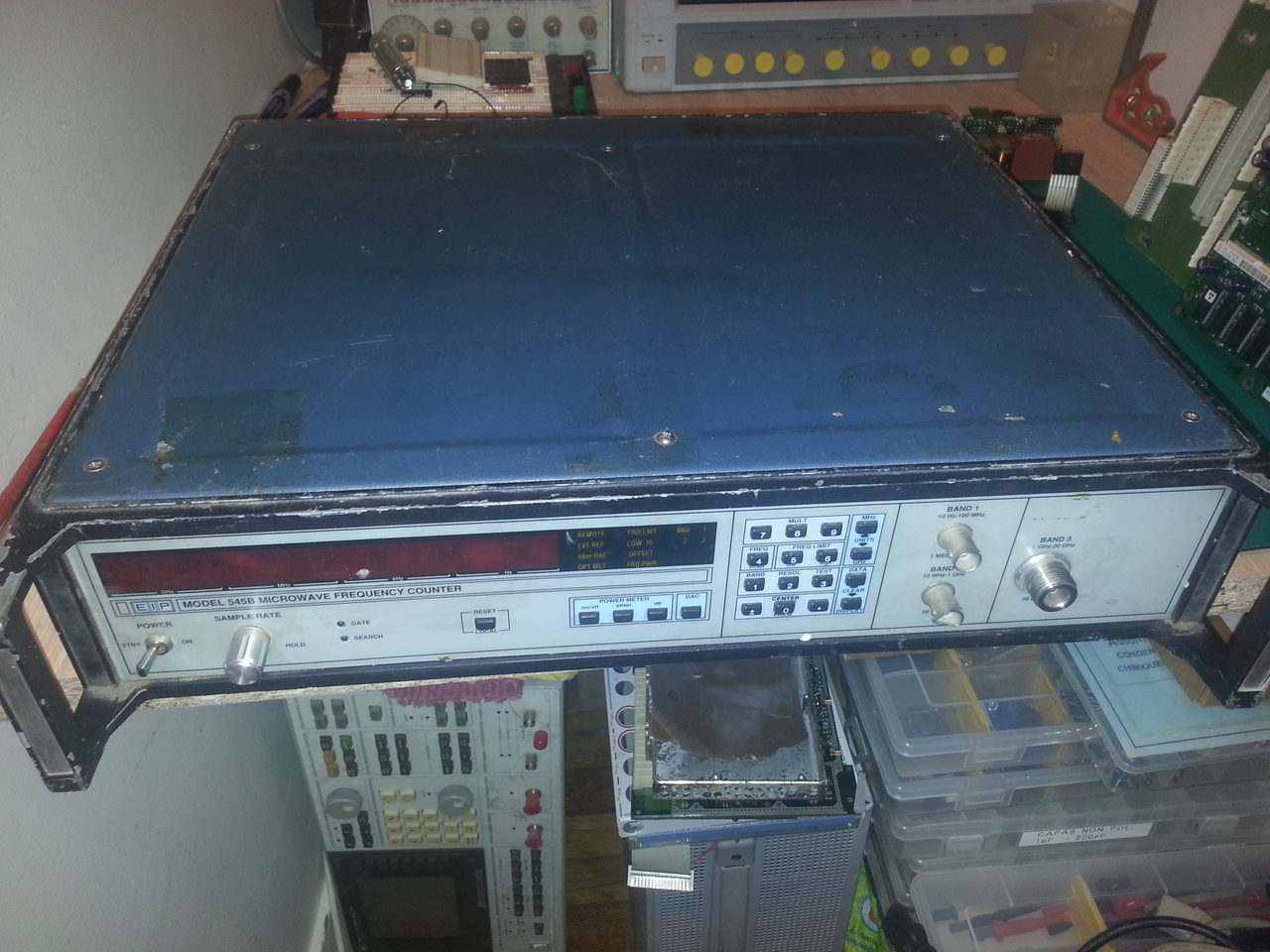
I received a few days ago, and the unit was, as adevrtised, not powering up, but also very dirty, with a bit of rust.
But after a good cleaning, the device seems to work
Now, I'd like to try to modify it to install the Power Meter (Option 2). This has been done by http://www.qsl.net/n/n9zia/vision/ and reproduced several times y SimonDialogs http://www.simonsdialogs.com/2014/09/eip-545a-microwave-counter-power-meter-upgrade/, but only for the 545A model, not the 545B I have.
Both models looks very similar, but not completely, for example, the GPIB board is different: the GPIB address is set via the test number '90' on the B model, whereas on the A model, the "test" 90 is used to configure the YIG calibration curve (it's on test 91 on the B model).
[edit] CPU boards are pretty different also[/edit]
So there are differences in firmwares, which makes me think I won't be able to simply use the EPROM images for the A model.
Has anyone ever tried this procedure on a 545B?
Has anyone have a 545B with option 2 and is willing to dump the EPROMs and make the files available somewhere?
Thanks,
David
PS: for a few more details on the repair of the unit, see my blog post
-
I've been digging a bit this power meter option, and I'm a bit puzzled by the modification made by WB4BPP (aka J. L. Trantham) on http://www.qsl.net/n/n9zia/vision/
Looking at the service manual for both 545A and the 578B (for which the Service Manual is also available and since it has the same CPU board than the 545B, it's probably a better source; the A107 board seems identical on all the versions), I cannot find anything related to the added EPROM on A107.
The differences of the schematics between the version with and without the Power Meter option only consists in the addition of U12 (8bit DAC) and CR3 (Schottky diode) and the removal of the "direct path" resistors R40 and R39 (as described in WB4BPP procedure).
So I wonder what these extra chips are used for (the U19, U20 and U21).
No doubt however that this option 2 must be "activated" somehow in the software, so I still need the main CPU's EPROM content for a 545B with option 2...
David
-
A closer look at these schematics, on the left are 2 tables with the unused references (Ref. Des. Not Used) and the power rails for each chip, and sure enough, U12, U19, U20 and U21 (as well as CR3) are listed as unused on the board without option 2 and added in the power rails in the version with option 2.
So It seems that they are not drawn on the schematic but needed nonetheless...
If I have the courage, I'll reverse ing. this missing part of the schematic, for the sake of understanding :-) -
In fact, in the service manual is this description:Quote
The POWER METER PROM (Option 02 only) contains a logic comparator (U21), a 2K x 8 PROM (U20), and a bus driver (U19).
The logic comparator is connected to the microprocessor address bus, and is configured to decode the 2K address range from 4000 Hex to 47FF Hex.
The comparator output drives the chip select of the PROM and the bus driver.
The PROM contains the Power Meter program as well as the power correction factors.
Bus driver U19 is used as a buffer for driving the microprocessor data bus
so maybe a modified A107 board is enough, without the need for a modified firmware of main CPU board... -
I've been looking a bit at the ROM dumps provided by GBPPR, as well as the EPROM dumps I just made from my unit, and I am pretty sure a modified A107 board will be enough to activate the power meter (no need for extra ROM images on the CPU board).
Also, the instructions they give for the modification talk about the calibration data, but not in details. In fact, the service manual says:QuoteThe power meter contains 690 correction factors. stored in PROM.
The 150 "power vs power" correction factors compensate for variations from
square law in the detector and power meter circuits. They are divided into
three tables. The first table corrects variations below 10 GHz. The second
corrects variations between 10 and 20 GHz. The third corrects variations above
20 GHz.
The 540 "power vs frequency" correction factors compensate for variations in
the detector output at different frequencies. "Power vs frequency" corrections
cover 0-27 GHz every 50 MHz. ' The power meter is calibrated at the factory
using specialized automatic test equipment.
Recalibration in the field is not recommended.
These values are stored at the very beginning of the EPROM. And looking at the calibration data of the unit used to extract the EPROM content for this Option 2 provided on GBPPR, it's clear that it has been calibrated only in the range 0-18GHz since from address 0x1FE, the same value (0x1A) is repeated again and again till the end of this calibration table (0x1FE is 150 (0x96) + 360 (0x168), and 360 because there are 360 50MHz steps in the 0-18GHz range).
I've ordered the parts I am missing to try this mod (probably next year :-) )
-
Has anyone ever tried this procedure on a 545B?
Hi,
54xA Opt.02 circuit doesn't work on 'B' model, the firmware part present in the Opt.02 EPROM is a extension firmware for the 54xA basic firmware and must be the same FW revision.
54xB firmware has already the option parts included, but it is normally disabled, the activation code reside in the CPU card EEPROM memory with the calibration table.
-
Hi,
54xA Opt.02 circuit doesn't work on 'B' model, the firmware part present in the Opt.02 EPROM is a extension firmware for the 54xA basic firmware and must be the same FW revision.
Yes I was a bit worried of such painful incompatibilities.54xB firmware has already the option parts included, but it is normally disabled, the activation code reside in the CPU card EEPROM memory with the calibration table.
Do you have tried yourself? I have not found anything (for now) in the manuals (the ones I could find) that would allow me to guess such a thing. For example, the 575B/578B service manual (ref. 5580032) also mention that "The PROM [on A107] contains the Power Meter program as well as the power correction factors."
Also, the A107 board in both manuals (545A and 575B) is referenced as 2020197-0X (with X from 1 to 8 depending on the combination of 10MHz ref and power measurement capabilities).
I also realized that the service manual for the 545A do explain the calibration procedure of the power meter in details (which the SM of the 575B does not).
David
-
Do you have tried yourself?
No, I have serviced professionally these counters 20 and more years ago.QuoteI have not found anything (for now) in the manuals (the ones I could find) that would allow me to guess such a thing. For example, the 575B/578B service manual (ref. 5580032) also mention that "The PROM [on A107] contains the Power Meter program as well as the power correction factors."
EIP manuals, not the revisited Phase-Matrix ones available, are extremely confusing in the 'A' to 'B' transition, see the CCN number in first page, in case of 545 models this transition was occurred between CCN# 2009 to 2010 and for 548 between 2309 to 2310, BUT the CCN# 2009 545A (2309 548A) is the same hardware as the 54xB (new boards), the old hardware ends with CCN# 2008 (2308).QuoteAlso, the A107 board in both manuals (545A and 575B) is referenced as 2020197-0X (with X from 1 to 8 depending on the combination of 10MHz ref and power measurement capabilities).
A107 board has the same P/N in old and new HW, the suffix change between two version and if Opt.02 is present or not, also for the 10MHz high stability options. Major change was for the CPU board A105 from P/N 2020195-xx to 2020215-xx, and various modification on other boards.
Some years ago I've helped a friend of mine with a 538 counter, my friend was desperately trying to obtain band 3 to work, he has modified the Converter Control board A108 to add the two multi-turn resistive trimmers and relative components missing in respect to old version manual... no joy. I have found that the instrument was an 538B HW with wrong front panel (538A does not exist), previously exchanged by someone
Restored the A108 board removing added components and executed the software calibration with success, sensitivity on band 3 was in specs Quote
QuoteI also realized that the service manual for the 545A do explain the calibration procedure of the power meter in details (which the SM of the 575B does not).
Yes, the procedure is briefly described, but it is not part of standard calibration of these counters, only the manufacturer has the system bench for this power meter calibration.
Years ago I have tried to recalibrate this option on request, with partial success because of insufficient power at 26GHz from the generator.
-
EIP manuals, not the revisited Phase-Matrix ones available, are extremely confusing in the 'A' to 'B' transition, see the CCN number in first page, in case of 545 models this transition was occurred between CCN# 2009 to 2010 and for 548 between 2309 to 2310, BUT the CCN# 2009 545A (2309 548A) is the same hardware as the 54xB (new boards), the old hardware ends with CCN# 2008 (2308).
Sorry, I made a typo, read CCNs for 545x as 2208, 2209, 2210 not as 20xx, for 548x are correct.
Small gift:
http://www.ko4bb.com/getsimple/index.php?id=download&file=EIP_PhaseMatrix/EIP_545_548/EIP_545A_Service_Manual.pdf
This manual is for CCNs 2209/2309, usable for your 545B, CPU board is the new p/n 2020215, some layouts are not updated as the potentiometers on A108, but schematic seems to be correct.
-
No, I have serviced professionally these counters 20 and more years ago.
That's a pretty good reason to have better clues than average Joe :-)Small gift:
http://www.ko4bb.com/getsimple/index.php?id=download&file=EIP_PhaseMatrix/EIP_545_548/EIP_545A_Service_Manual.pdf
This manual is for CCNs 2209/2309, usable for your 545B, CPU board is the new p/n 2020215, some layouts are not updated as the potentiometers on A108, but schematic seems to be correct.
Yes that's one of the manuals I have found (ko4bb is such a bless), I'm also referring to this 57XB one (CCN 1809/2009) in which the CPU board as well as the GPIB board (for example) seems to be exactly the same as the one I have in my unit. I give the example of the GPIB board because with this one, there are no switches to configure the address, this is achieved by 'test 90' config menu (the YIG calibration menu begin 'test 91'), which is what is described in the 57XB manual and matches my unit.
So my assumption is that the 57XB is the same unit as the 54XB one, with the ref loop (A103) and phase lock (A104) boards populated (and probably an adapted firmware).
-
Fun fact: in fact, the power meter is working "out of the box". When I activate it, it display the triple E for a few seconds, then display a power (obviously completely uncalibrated) with a "resolution" of 3dB, since the second AD7526 (U12) is not present.
So I've installed an AD7526 in U12 socket, a FH1100 equivalent diode (a QSCH1245) and removed R39, et voilà! the power meter now works with the 0.1dB resolution!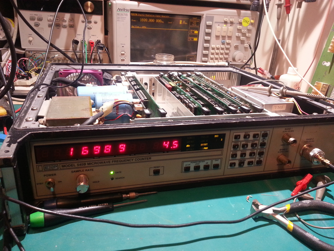
Now i need to figure out where the calibration curves are stored in the memory. I don't think it's located at the same address as it was on the 545A (0x4000 in the EPROM that can be installed on A107) since the ROM on the CPU board do have content in this 0x4000->0x47FF mem area.
It might even be located in the EEPROM.
I still have a few issues I need to fix:
- I've replaced the CR4 zener diode on A107; it was dead (open), but the sensibility remains too low on band 3 (I can sometimes "catch" a signal at -15dBm or so, but it's unstable). The reference voltages on pin 2 of U14 (LM393 comparator) is now a stable -100mV as described somewhere in the service manual, but the signal detection circuitry is still not working properly. I need to double check the capacitors on this A107 board, since a quick in-place check with a DER DE-5000 LCR meter showed some strange results for some of them (surprisingly, not the tantalum ones, but I'll check theses again with a lead desoldered from the board).
- When I power the device, it's set with a 200MHz offset and only 5 digits of resolution. I guess this is the part of the "SPECIAL WB68" version of the firmware I have, but I find it quite annoying.
- Replace the bent BNC connector for band 2.
- And run a deep check / calibration of the unit.
I've started to (partially) disassemble the firmware to find where I need to change these initial values. Dawn it's been a looong time since I've played with 6800 assembly code! I was also trying to figure out how to activate the power meter, but this is now magically fixed :-)
I'll write a follow up on my blog with the things I've understood in the disassembled firmware when I'm done.
David
-
I still have a few issues I need to fix:
- I've replaced the CR4 zener diode on A107; it was dead (open), but the sensibility remains too low on band 3 (I can sometimes "catch" a signal at -15dBm or so, but it's unstable). The reference voltages on pin 2 of U14 (LM393 comparator) is now a stable -100mV as described somewhere in the service manual, but the signal detection circuitry is still not working properly. I need to double check the capacitors on this A107 board, since a quick in-place check with a DER DE-5000 LCR meter showed some strange results for some of them (surprisingly, not the tantalum ones, but I'll check theses again with a lead desoldered from the board).
Have you checked the calibration on the YIG bandpass filter? If it's out of adjustment, the signal won't get through to the rest of the system or will be badly attenuated. I have a unit that seems to be made of pieces from multiple systems. The YIG filter was about as far out of adjustment as it could be!
Ed
-
Have you checked the calibration on the YIG bandpass filter? If it's out of adjustment, the signal won't get through to the rest of the system or will be badly attenuated. I have a unit that seems to be made of pieces from multiple systems. The YIG filter was about as far out of adjustment as it could be!
Yes I've been thinking something like this may also happen. I'll try to check a bit if the YIG calibration is reasonably OK, at least up to the frequencies I can check for now with the equipment I have.
Ed
David
-
Now i need to figure out where the calibration curves are stored in the memory. I don't think it's located at the same address as it was on the 545A (0x4000 in the EPROM that can be installed on A107) since the ROM on the CPU board do have content in this 0x4000->0x47FF mem area.
It might even be located in the EEPROM.
Just realized HighPrecision wrote a few posts back the PM calibration table is in the EEPROM... doh! Whatever, I still need to find where.
I've found the tests vector table in the firmware, and there is no other (undocumented) test than the ones listed in the service manual (1 up to 11, 90 and 91). Could have been a 92 or any other value to enter a PM calibration menu but it seems no such menu exists... So one have to burn the values in the EEPROM somehow. -
- When I power the device, it's set with a 200MHz offset and only 5 digits of resolution. I guess this is the part of the "SPECIAL WB68" version of the firmware I have, but I find it quite annoying.
Special WB68 is a BAND 3 Low end frequency extension to 0.6GHz (600MHz) with reduced specs for sensitivity and power meter dynamic range.
Frequency offset and resolution setting have not to do with this special option, in the EEPROM there are saved the instrument power-on defaults.Just realized HighPrecision wrote a few posts back the PM calibration table is in the EEPROM... doh! Whatever, I still need to find where.
As I said the power meter calibration is NOT part of the standard calibration procedure, there is no related TEST xx for this.
I've found the tests vector table in the firmware, and there is no other (undocumented) test than the ones listed in the service manual (1 up to 11, 90 and 91). Could have been a 92 or any other value to enter a PM calibration menu but it seems no such menu exists... So one have to burn the values in the EEPROM somehow.
The EEPROM on CPU board is allocated from 0x0800 to 0x0FFF
Power meter calibration table start at 0x0810
YIG DAC calibration table start at 0x0C00, but I have no idea if the special option WB68 start at this location (shifted data ?).
You can use TEST 10 to modify the EEPROM locations, or via GPIB with TA10 command, obviously the write-protect switch should be disabled.
I suggest to save the entire EEPROM before any attempt to change data.
Edit: typos
-
Thanks a lot for all these informations...
0x0810 was on the list of possible "culprits", but I was not near a definitive conclusion yet. Quite a time saver!Special WB68 is a BAND 3 Low end frequency extension to 0.6GHz (600MHz) with reduced specs for sensitivity and power meter dynamic range.
Frequency offset and resolution setting have not to do with this special option, in the EEPROM there are saved the instrument power-on defaults.
I noticed I could go quiter lower the 1GHz on band 3, haven't thought it might be thanks to the WB68 special version.As I said the power meter calibration is NOT part of the standard calibration procedure, there is no related TEST xx for this.
The EEPROM on CPU board is allocated from 0x0800 to 0x0FFF
Power meter calibration table start at 0x0810
YIG DAC calibration table start at 0x0C00, but I have no idea if the special option WB68 start at this location (shifted data ?).
I had these ones from the service manual, yes. And it does not look like the location has moved somewhere else.You can use TEST 10 to modify the EEPROM locations, or via GPIB with TA10 command, obviously the write-protect switch should be disabled.
I suggest to save the entire EEPROM before any attempt to change data.
I already have dumped the whole memory: EPROM + EEPROM (which I will make available on my blog as soon as I have time to write part 2), which is what I've disassembled (the hard part being to locate the constant/data areas... for now, I still have many places where the disassembled code is just garbage due to a CONST area not properly handled).
But no way I enter the calibration values using TEST10! :-)
Another question, maybe I missed this in the service manual, but is there a procedure to check wheter the YIG calibration is correct?
I was thinking about how I can check this (to address my sensibility problem), and I'm not sure what's the best way of doing this verification.
Don't think I can force the YIG to stay centerered at a given freq, without scanning (then inject a know signal and measure the power ouput from A203. Can I? Setting the low/high freq limits to the same value maybe?
David
-
Another question, maybe I missed this in the service manual, but is there a procedure to check wheter the YIG calibration is correct?
I was thinking about how I can check this (to address my sensibility problem), and I'm not sure what's the best way of doing this verification.
Don't think I can force the YIG to stay centerered at a given freq, without scanning (then inject a know signal and measure the power ouput from A203. Can I? Setting the low/high freq limits to the same value maybe?
David
I had to go digging to find it. It's been 5 years since I did this. It's in Section 7 of the manual and it's called "Converter Calibration". My unit started out with a sensitivity of ~ -19 dBm @ 1 GHz. It was so far out of adjustment that the adjustment procedure didn't work. I did more digging and I've got a couple of pages of notes that I can transcribe if necessary. I ended up with a sensitivity that matched the spec of -30 dBm up to at least 11.5 GHz. That's the highest frequency I could generate.
Ed -
Another question, maybe I missed this in the service manual, but is there a procedure to check wheter the YIG calibration is correct?
A quick method only to verify if the YIGF is correctly centered, is to inject a small bipolar current into feedback node of U3 OP-Amp on A108 board, in example: a potentiometer between +12V and -12V, the wiper connected with a reasonable high value resistor in series to the (-) input of Op-Amp. -
A quick method only to verify if the YIGF is correctly centered, is to inject a small bipolar current into feedback node of U3 OP-Amp on A108 board, in example: a potentiometer between +12V and -12V, the wiper connected with a reasonable high value resistor in series to the (-) input of Op-Amp.
Thanks a lot. Pretty obvious once one does look at the schematics of the YIG driver... I'll give a try ASAP.
David -
Thanks a lot. Pretty obvious once one does look at the schematics of the YIG driver... I'll give a try ASAP.
This test is intended to be done in 'search mode' of the counter (no signal detected) for lowest power level to start count, counter firmware execute a fine tune of the YIG filter at first signal acquisition.
Another weak point maybe the YIG current sense resistor (the big one on A108) is out of tolerance.
-
Another weak point maybe the YIG current sense resistor (the big one on A108) is out of tolerance.
Just did a quick check and it's bang on. It would have been too easy :-)
-
Special WB68 is a BAND 3 Low end frequency extension to 0.6GHz (600MHz) with reduced specs for sensitivity and power meter dynamic range.
Frequency offset and resolution setting have not to do with this special option, in the EEPROM there are saved the instrument power-on defaults.
After digging more in the disassembly of the firmware, and comparing the RAM content juste after booting the and after having changed these settings, it appears that these default values **are** hardcoded in the firmware. So, special really means special: it's most probably a very specific crafted firmware for a specific customer...
I "dumped" the RAM using TEST10 via GPIB (with a simple python script).
Now, I need to try to 'fix' this firmware, fix my sensitivity problem, and calibrate the device...
-
Informations about WB68 are very scarce, all I have is this:Code: [Select]
WB-68 B3 .6GHZ to 20 GHZThat's all, this option is possible ONLY on 545B and not on a 548B, the extra space for YIG DAC calibration (to 26.5GHz) is used for this low end extension, probably data shift as I said.
600 MHZ to 1 GHZ 0 to -20 dBm
1 GHZ to 20 GHZ +5 to -20 dBm
BCD remote programming (this is a special on a 545B)
GP-IB (option 08)
          instrument configurated with BCD interface. GP-IB board
          and rearpanel cable physically located in unit.
          BCD to GP-IB and vice versa can be done within 15 min.
This probably mean also that the Microwave Convertor is a special version for this WB68 option, my informations on A203 testing are pratically useless. -
Code: [Select]
instrument configurated with BCD interface. GP-IB board
and rearpanel cable physically located in unit.
BCD to GP-IB and vice versa can be done within 15 min.
I was wondering why I have this BCD board in a blank slot with the device, now I know!
-
I've been investigation a bit more this evening the sensibility problem of my 545B. I haven't been able to improve anything injecting a small current on the negative input of the log amplifier driving the YIG.
I've also tried a quick calibration of the YIG, without noticeable effect either.
Then I've passed (again for some of them) the troubleshooting tree from the service manual, and I've found something wrong:
when locked on a (strong enough) signal on band 3, the IF sits at roughly 127.9MHz instead of 125MHz as described in the manual, for which the troubleshooting tree concludes that "VCO or LOCK CIRCUITRY on A108 BAD".
So I've probed most of the passive components on A108 involved in the lock circuitry of the VCO, and every looks OK so far. I've also removed all the chips to clean (with a bit of Deoxit) the DIP sockets. It's probably useless but cannot hurt.
Tomorrow I'll try to probe a bit the several test points of this section of the circuit to see if I can find something strange, but I'm afraid the problem might be in A201 in which I would have preferred not to put my nose...
David