-
I now have the parts and the PCBs, but not enough time to assemble yet.
Have you assembled and tried one yet?
I'm currently designing an adapter PCB for this same connector, and as far as I can tell, your connector is arse-about.
You would need to mount it to the bottom of the PCB shown in reply #61.
Or is it me that has it wrong?
All these have DIO1 at top-left when looking into the connector with the wide side at the left. And that would also go to the top-left pad on your PCB, but your DIO1 is at the bottom-left!?
I was just about to send my design to JCLPCB after a final check, but now I'm confused....
No haven't assembled mine yet. Nor did I check the connector pin-out before I sent my Gerbers out.
I started by copying other PCB designs. If I am wrong, so are they. I have checked the pin numbers on the connectors I have. My PCB is OK. Pin 1 marked on the connector puts it on the bottom left.
The boards I have are for lead-less devices. A little challenging to solder, but I have a hot air station.
I have redesigned my PCB to use a leaded flat pack type package for the MCU. The PCB is just a few mm deeper, but still very small. I have not had this PCB version made.
-
My PCB is OK. Pin 1 marked on the connector puts it on the bottom left.
Yes, same on my connector. I was following signal names rather than pin numbers.
Two of the links in my previous post appeared to be views of cable plugs looking into the mating side, but these are piggy-back, and the views were looking into the female side of them, it seems. (Or looking through the adapter to the instrument connector)
Someone else had similar confusion, but provided a definitive diagram:-
https://www.eevblog.com/forum/projects/ar488-arduino-based-gpib-adapter/msg3379350/#msg3379350
Thanks for helping clear this up.
(Now back to my orginal PCB version for JLCPCB) -
Out of curiosity, what about the AR488 by WaveyDipole? Why would you not use that and the Uno R3 shield @artag designed so you can plug a 24 pin IDC cable on into the shield and attach up to 10 GPIB devices using IDC Centronics coonnectors.
There is a very long thread about it on this forum.
In any case, the price of name brand GPIB adapters that aren't fakes is ridiculous. So another design is always useful. Thank you.
Have Fun!
Reg -
If this works OK I might be interested in one Darren, but I can only scrape together $88,666.42, I hope that is enough.
-
If this works OK I might be interested in one Darren, but I can only scrape together $88,666.42, I hope that is enough.
I wouldn't normally accept that amount for payment.
I usually require at least a 10% deposit.
-
I'm using xyphro’s UsbGpib adapter on Linux (Debian) and it works perfectly fine as a usbtmc interface. I haven't used it with any NI / proprietary tools and wrote some python using python-usbtmc https://github.com/python-ivi/python-usbtmc
The python-usbtmc project has a udev rules sample file, I updated it to use the vendor id for the usbtmc device and update the group to dialout. So no need to run things as root. If I need to add some real time graphing, I can use python's matplotlib.
e.g.
#!/usr/bin/python3
import usbtmc
import time
# DMM 34401A
instr = usbtmc.Instrument(0x03eb, 0x1041)
print(instr.ask("*IDN?"))
print(instr.ask("SYST:ERR?"))
print(instr.ask("MEAS:VOLT:DC?"))
-
I'm using xyphro’s UsbGpib adapter on Linux (Debian) and it works perfectly fine as a usbtmc interface. I haven't used it with any NI / proprietary tools and wrote some python using python-usbtmc https://github.com/python-ivi/python-usbtmc
I haven't even begun to look at code but I will definitely bookmark that link. I will need to start by learning Python. -
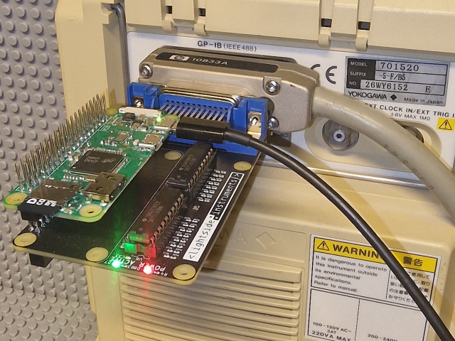
Check the gpib4pi board released in 2023. It provides GPIB interface solution based on linux-gpib toolchain and its bitbang driver. It is 100% open-source hardware (OSHWA certified NO000003 - https://certification.oshwa.org/no000003.html ). It has a standard IEEE-488 compliant SN75160/1 drivers. You can set up a wireless LAN/GPIB gateway with a Raspberry Pi Zero W described in this application note https://www.hackster.io/lightside-instruments/wireless-lan-gpib-gateway-with-open-source-hardware-6e0af8
-
Check the gpib4pi board released in 2023. It provides GPIB interface solution based on linux-gpib toolchain and its bitbang driver. It is 100% open-source hardware (OSHWA certified NO000003 - https://certification.oshwa.org/no000003.html ). It has a standard IEEE-488 compliant SN75160/1 drivers. You can set up a wireless LAN/GPIB gateway with a Raspberry Pi Zero W described in this application note https://www.hackster.io/lightside-instruments/wireless-lan-gpib-gateway-with-open-source-hardware-6e0af8

Hi
I am committed to the USB-GPIB adapter. I have modified the pcb design (twice) and figured out what software mods I need to make for my two LED version. The pcbs and parts are waiting for me to put them together.
-
Out of curiosity, what about the AR488 by WaveyDipole? Why would you not use that and the Uno R3 shield @artag designed so you can plug a 24 pin IDC cable on into the shield and attach up to 10 GPIB devices using IDC Centronics coonnectors.
There is a very long thread about it on this forum.
In any case, the price of name brand GPIB adapters that aren't fakes is ridiculous. So another design is always useful. Thank you.
Have Fun!
Reg
The initial question in this thread was to find an adapter which can be accessed through the Visa API. The AR488 doesn't do that - it emulates the Prologix USB adapter, which communicates over a serial-over-USB emulation.
I guess it's possible to write a Visa interface for Prologix but I don't know that anyone's done that. Or modify the python interface to use Prologix instead of Visa, but then you end up with a Python API which is another ratsnest of incompatibility.
It's also possible, with some reassignment of pins, to make the xyphro software work with AR488 hardware. However, the xyphro software makes better use of the Atmega's pins : some are not available on the Arduino boards which results in inefficiences such as having to bit-address some ports instead of byte-address. IIRC I laid out the Arduino Pro Micro pcb to work as well as possible (eg write the 8 bit data port in only two writes) but the original xyphro assignment is better.
-
Could you post your version of the code for Arduino Pro Micro? I'd like to try it, without having to make a custom PCB.
-
The initial question in this thread was to find an adapter which can be accessed through the Visa API. The AR488 doesn't do that - it emulates the Prologix USB adapter, which communicates over a serial-over-USB emulation.
I guess it's possible to write a Visa interface for Prologix but I don't know that anyone's done that. Or modify the python interface to use Prologix instead of Visa, but then you end up with a Python API which is another ratsnest of incompatibility.
I use my AR488 adapters with pyvisa exclusively and they work great. Here's an example for reading DC voltage from an HP 34401A:Code: [Select]import pyvisa
from sys import platform
rm = pyvisa.ResourceManager('@py')
if platform == "linux" or platform == "linux2":
# Linux
multimeter = rm.open_resource('ASRL/dev/ttyUSB0::INSTR')
elif platform == "darwin":
# macOS
multimeter = rm.open_resource('ASRL/dev/cu.usbmodem101::INSTR')
elif platform == "win32":
# Windows, COMx = ASRLx
multimeter = rm.open_resource('ASRL19::INSTR')
multimeter.write('++rst')
multimeter.close()
sleep(2)
multimeter.open()
multimeter.baud_rate = 115200
multimeter.timeout = 5000
multimeter.write_termination = '\n'
multimeter.read_termination = '\n'
multimeter.write('++addr 22')
multimeter.write('++auto 2')
multimeter.write('++eos 2')
multimeter.write('++eoi 1')
multimeter.write('*RST')
multimeter.write('*CLS')
print(multimeter.query('*IDN?'))
multimeter.write('CONF:VOLT:DC 10,0.001')
try:
while(True):
print(multimeter.query('READ?'))
except KeyboardInterrupt:
multimeter.write('*RST')
multimeter.write('*CLS')
multimeter.write('++loc')
multimeter.close()
rm.close()It's also possible, with some reassignment of pins, to make the xyphro software work with AR488 hardware. However, the xyphro software makes better use of the Atmega's pins : some are not available on the Arduino boards which results in inefficiences such as having to bit-address some ports instead of byte-address. IIRC I laid out the Arduino Pro Micro pcb to work as well as possible (eg write the 8 bit data port in only two writes) but the original xyphro assignment is better.
I'm wondering if the opposite is true, i.e. that you can use AR488 software with the xyphro hardware by changing up the pin assignments. I've been playing around with xyphro adapters and I like the form factor. I'd be interested in trying to get the AR488 firmware running on the xyphro adapter... -
you have to remap some pins ...
-
Looking at the schematics for the xyphro vs the Arduino Pro Micro, I think it is possible to run AR488 on the xyphro adapter but I think it requires a custom Arduino board definition. Two of the pins the xyphro uses as data lines are used as the RX and TX LEDs on the Pro Micro, so I think you'd need an Arduino board definition that remapped those to other pins to be able to flash AR488 on the xyphro hardware.
I might give it a shot if I have enough time to kill one day... -
I have assembled one USB-GPIB adapter and I am now trying to load the firmware.
I have an Aliexpress usbasp programmer. I am running avrdude on Ubuntu.
I have successfully run the following commands:Code: [Select]avrdude -P usb -c usbasp -p m32u4 -e -Uefuse:w:0xcb:mavrdude -P usb -c usbasp -p m32u4 -e -U flash: "FLASH.BIN" -vvvv
avrdude -P usb -c usbasp -p m32u4 -e -Uhfuse:w:0xd8:m -Ulfuse:w:0xff:m
avrdude -P usb -c usbasp -p m32u4 -U flash:w:BootLoader.hex
These commands are based on instructions earlier in this thread and they return messages of success.
For the benefit of others:
-P the port
-c programmer type
-p MCU type
-e erase first. Necessary before programming.
seeCode: [Select]/etc/avrdude.confandCode: [Select]man avrdudeor/and
https://www.nongnu.org/avrdude/user-manual/avrdude_3.html#Option-Descriptions
for full details.
I am now stuck on what to do next. I understand this is a copy command, but I can't figure out what my destination should be. I was expecting another avrdude command at this point.Code: [Select]cp TestAndMeasurement.bin /run/media/baettig/GPIBUSBBOOT/FLASH.BIN# verify with md5sum, umount, unplug
-
I am now stuck on what to do next. I understand this is a copy command, but I can't figure out what my destination should be. I was expecting another avrdude command at this point.
Code: [Select]cp TestAndMeasurement.bin /run/media/baettig/GPIBUSBBOOT/FLASH.BIN# verify with md5sum, umount, unplug
Did you see the note re. Linux on the README ?QuoteOn Linux, there is a bug with the LUFA mass storage that means it is required to use
Code: [Select]dd if=TestAndMeasurement.bin of=/mnt/FLASH.BIN bs=512 conv=notrunc oflag=direct,sync -
Yes, I did not see the note.
Did you see the note re. Linux on the README ?Code: [Select]dd if=TestAndMeasurement.bin of=/mnt/FLASH.BIN bs=512 conv=notrunc oflag=direct,sync
The dd command is one I only use as the option of last resort.
I think the root of my problem is a dumb assumption. I assumed that the initial firmware would be all loaded via the programmer.
I now see that the process requires the programming of the the boot loader via the ISP connector, followed by copying the firmware via the usb connector.
OK so I have connected Win10 (dual-boot PC) to the usb-gpib usb-C connector. I see:Code: [Select]GPIBUSBBOOT(D:)
EEPROM.BIN 1KB
FLASH.BIN 24KB
So that looks like it is working.
Then I tried copying TestandMeasurement.bin via the usb connector and got the error message in the attached image.
FLASH.BIN is taking up all the space.
For me, it makes no sense to re-program via the USB port.
To enable the boot loader to load new firmware, I need to remove the enclosure and short two pins on the ISP connector. Then download the firmware via the usb connector using the data destroyer dd command or Win10 copy.
If I re-program the firmware via the ISP connector, I need to remove the enclosure and plug in my usbasp programmer using the benign avrdude program.
To use the usb connector really requires an externally accessible push switch to short the ISP pins without removing the enclosure. I did look at this option when designing my PCB but did not include one. I think I will add that option on the pcb (fit for but not with).
I have make progress. I have confirmed:
the ISP works,
the usb-C works,
the MCU works.
but I have not yet been able to load the usb-gpib firmware. I am still doing something wronng.
-
In theory, you could use the arduino style bootloader and just program directly from USB without shorting any pins. I'm not sure why the flash bootloader was chosen

-
In theory, you could use the arduino style bootloader and just program directly from USB without shorting any pins. I'm not sure why the flash bootloader was chosen
Right now I am just trying to get the firmware installed and running. I plan to modify the software to run the two status LEDs because two LEDs is always better than one. -
I am thinking if I don't install (delete) FLASH.BIN, I will have enough space for the usb-gpib firmware. My understanding of the software is that the FLASH.BIN code is only called if the 2 pins on the ISP connector are shorted.
-
Code: [Select]
avr-size --mcu=atmega32u4 --format=avr TestAndMeasurement.elf
AVR Memory Usage
----------------
Device: atmega32u4
Program: 9190 bytes (28.0% Full)
(.text + .data + .bootloader)
Data: 241 bytes (9.4% Full)
(.data + .bss + .noinit)
I shouldn't take a lot of space. I followed the instructions on getting the bootloader flashed, unplug and plug usb back in, short pin 4 & 6 of the ISP header (MOSI & GND) for abour 3 seconds and the bootloader should appear as a flash drive. Mount it and then copy the file acrossCode: [Select]sudo mount /dev/sdb /media/avr
sudo dd if=TestAndMeasurement.bin of=/media/avr/FLASH.BIN bs=512 conv=notrunc oflag=direct,sync
sudo umount /media/avr
This works as advertised for me. -
For me the problem is that the FLASH.BIN file is taking up 24kB of 32kB memory, so no room for the measurement app file.
-
what is the FLASH.BIN file ?
There are 2 artefacts, the bootloader.hex and the TestAndMeasurement.bin files. The bootloader is programmed through the avrdude command as described in the readme.
Once the bootloader presents the device as a flash drive, you copy the TestAndMeasurement.bin file to the drive and name it FLASH.BIN, that way the bootloader can program the flash once the file is written.
avr-size tells me TestAndMeasurement.elf is about 9K, should not be anywhere close to 20k+
-
FLASH.BIN appears way back in reply No.41. I missed the bit about renaming it.
I will do what you have done and that should work. -
Hi
I didn't do what you said. I tried something else.
I started by copying the TestAndMeasurement.bin file to FLASH.BIN. Same file, different name.
For all of the commands below, the USB-GPIB adapter was connected to a usbasp programmer via the ISP connector.
I ran this command in Linux:Code: [Select]>$ avrdude -P usb -c usbasp -p m32u4 -e -U flash:w:FLASH.BIN
and got the following messages in response:Code: [Select]avrdude: warning: cannot set sck period. please check for usbasp firmware update.
avrdude: AVR device initialized and ready to accept instructions
Reading | ################################################## | 100% 0.00s
avrdude: Device signature = 0x1e9587 (probably m32u4)
avrdude: erasing chip
avrdude: warning: cannot set sck period. please check for usbasp firmware update.
avrdude: reading input file "FLASH.BIN"
avrdude: input file FLASH.BIN auto detected as raw binary
avrdude: writing flash (9312 bytes):
Writing | ################################################## | 100% 5.40s
avrdude: 9312 bytes of flash written
avrdude: verifying flash memory against FLASH.BIN:
avrdude: load data flash data from input file FLASH.BIN:
avrdude: input file FLASH.BIN auto detected as raw binary
avrdude: input file FLASH.BIN contains 9312 bytes
avrdude: reading on-chip flash data:
Reading | ################################################## | 100% 4.74s
avrdude: verifying ...
avrdude: 9312 bytes of flash verified
avrdude: safemode: Fuses OK (E:F3, H:D8, L:FF)
avrdude done. Thank you.
After this, the status LED started flashing on the GPIB adapter. So this looks like success.
I like writing this sort of thing into Linux shell scripts to reduce the chance of error. I have 4x more adapters to build and program. A script means I can exactly reproduce a complex command sequence.
My script looks like this:Code: [Select]#!/bin/bash
# uploads usb-gpib firmware to usb-gpib adapter.
# version 1.2 13 Nov 2023
avrdude -P usb -c usbasp -p m32u4 -e -Uefuse:w:0xcb:m
avrdude -P usb -c usbasp -p m32u4 -e -Uhfuse:w:0xd8:m -Ulfuse:w:0xff:m
avrdude -P usb -c usbasp -p m32u4  -U flash:w:BootLoader.hex
# -> yields
# avrdude: safemode: Fuses OK (E:CB, H:D8, L:FF)
# copy the TestAndMeasurement.bin file to FLASH.BIN. Probably not necessary, but it worked.
# This command loads the firmware.
avrdude -P usb -c usbasp -p m32u4 -e -U flash:w:"FLASH.BIN"
# run this command to read and verify the firmware
avrdude -P usb -c usbasp -p m32u4 -U flash:v:"FLASH.BIN"
At the end of running these commands, the status LED slowly flashed on the usb-GPIB adapter. So it all appears to have worked.
I then tried shorting the two ISP pins to try and get the adapter to appear as a drive, but that didn't work.
The final test I haven't done is to try controlling a device. I have a HP 3478A multi-meter. I just need to find some software compatible with the adapter. One I tried was looking for a COM port.