-
Forgive me if this not the correct section for the following question but I'm not sure where else I should post it. Mods, please feel free to move it if needed.
Considering a DMM, which reads a value of 0.1Ω when the probes are sorted. If we do a continuity test on a device and we measure 0.3Ω, can we assume that the actual resistance between the two points is 0.2Ω? i.e 0.3Ω minus the resistance of the probes (0.1Ω)?
And if so, what's the benefit of a 4W multimeter? -
1) yes
2) to avoid the problem encountered in 1) -
It is OK to subtract the reading one gets from just shortening the probes. That is about the best one can do with 2 wire ohm mode, though the resitance to subtract may not be that constant - it can vary with the quality of the contact, though one may not see this with 0.1 ohm resolution.
The 4 wire ohm mode avoids the contact and cable resistance problem, with no need to the contact resistance to be stable. -
Considering a DMM, which reads a value of 0.1Ω when the probes are sorted. If we do a continuity test on a device and we measure 0.3Ω, can we assume that the actual resistance between the two points is 0.2Ω? i.e 0.3Ω minus the resistance of the probes (0.1Ω)?
No, because there will be two extra resistances between the points of the probes and the circuit.And if so, what's the benefit of a 4W multimeter?
It takes the resistance of the probes completely out of the equation.
nb. You can also do it with two multimeters and a current source, you don't need a special 4W meter.
-
No, because there will be two extra resistances between the points of the probes and the circuit.
Well, one extra point of contact anyway.
You're right of course, there's an extra unknown (or unknowns) but in practice who would not just subtract the 0.1Ω either mentally or using the meter's "rel" function (if it has one, though all but very low end DMMs do). -
It might be worth pointing out that a normal DMM which only offers 2-wire measurement is not a great instrument for measuring 200 milli-ohms anyway, as Fungus hints the errors caused by contact resistance mean your accuracy will be about a single digit (OK, that might suffice for some applications).
As ever, what are you trying to measure, and why? -
As ever, what are you trying to measure, and why?
Continuity between PE and different points of the enclosure. -
4W measurements (Kelvin type) separate current and sense path.
That means that sense path is high impedance and measures voltage so any resistance (including contact resistance) has little influence.
On the other hand, as current source, 4W meters use constant current source, that will force certain constant current even if wiring and contact resistance in that current contour varies and is not stable. So you have stabilized current and separate voltage path.
Copper wires have quite high thermal coefficient. If you do 2W measurement by shorting wires, then measuring resistor, by the time you measure resistor things change... It is not stable.
4W measurement technique helps with measurements, compensates in changes and differences in cables etc etc... By the time you need to measure something below, say 10Ω, influence from cables is quite visible. Below 1Ω, influence form cables can be greater than DUT..
To put it colloquially, with 2W measurements your meter calibration is valid at multimeter sockets. With 4W calibration is (almost) valid (assuming correct good quality cabling and connection) at point of measurement, I.E at cable probes connected to DUT...
It is not exactly like that (metrology guys will kill me for this oversimplification) but it illustrates the difference.
4W purpose is to try to achieve that.
-
Continuity between PE and different points of the enclosure.
It's not so useful to know with high accuracy. If the chassis is mains connected (as you have PE), PE is meant to be able to conduct mains voltage and short circuit current. Appropriate wiring for high current should be used. PE wire must be secured to chassis with a strong screw, preferably using a star washer that bites into the metal.
But if you have any kind of conductivity that your DMM can show (such as under 1 ohm), it will probably be fine. Of course, depending on application, you might want all parts of the chassis to have good connection between them (for shielding, EMI, ESD etc.). But again, you just want good conductivity, but the exact value isn't a big deal. -
Continuity between PE and different points of the enclosure.
It's not so useful to know with high accuracy. If the chassis is mains connected (as you have PE), PE is meant to be able to conduct mains voltage and short circuit current. Appropriate wiring for high current should be used. PE wire must be secured to chassis with a strong screw, preferably using a star washer that bites into the metal.
But if you have any kind of conductivity that your DMM can show (such as under 1 ohm), it will probably be fine. Of course, depending on application, you might want all parts of the chassis to have good connection between them (for shielding, EMI, ESD etc.). But again, you just want good conductivity, but the exact value isn't a big deal.
Well, usually there are some requirements that have to be met. Maximum of 100mΩ between the PE and any part of the enclosure, if I'm not mistaken. -
AFAIK you need a special tester for that which uses high AC currents (up to tens of Amps). At least if you want to adhere to standards.As ever, what are you trying to measure, and why?
Continuity between PE and different points of the enclosure. -
You could have a tiny wire or connection somewhere measuring 100 mΩ, but it won't last the short circuit current that PE is designed for. So it depends on your application. If it's for hobby use, use visually good wire connection, trust your DMM and use double fused IEC socket and you are good to go. If this is for some commercial application, it gets complicated...
-
My meter has resolution down to 1 milliohm but I doubt that I can get accurate reading of a 0.2 ohms resistance.
-
On some better meters the REL function works in ohms as well. While this helps take the lead resistance out of the measurement, it does not help with contact resistance to the DUT. Even with a 4W Kelvin arrangement, you still need to ensure clean, low resistance contact otherwise you will still be making inaccurate measurements.
-
For the normal case of measuring say a low value current shunt, you'd do a four wire measurement by feeding a current, for example from a bench supply, through the resistor and measure the voltage across the resistor at its terminals (separate connections for voltage and current). Then divide the voltage by the current, and you get the resistor. For very low value resistors it helps to use a larger current, like 1A, to increase resolution.
For earthing resistance measurements there will likely be specific standards in your local electrical code. I wouldn't assume a random DIY solution would be sufficient there. -
Considering a DMM, which reads a value of 0.1Ω when the probes are sorted. If we do a continuity test on a device and we measure 0.3Ω, can we assume that the actual resistance between the two points is 0.2Ω? i.e 0.3Ω minus the resistance of the probes (0.1Ω)?
And if so, what's the benefit of a 4W multimeter?
If your meter uses a 1mA test current (typical but not universal) then a resistance of 0.3R will result in a voltage of 300µV. So how well your meter can measure the difference between 0.1R and 0.3R depends on both the ability of the meter to resolve the 200µV difference and on any small contact resistance you introduce in the circuit when you change the position of the leads from shorted together to measuring your resistance. You would want to do this a few times each way to see how repeatable your measurements are. If they seem reliably repeatable, it wouldn't be all that unusual for decent 4.5-digit meter (or better) to be able to resolve those measurements to at least 1 digit. However it is often a tricky and error-prone process. Using a better meter and 4W kelvin-clip leads you can usually get 2-3 digits accuracy because you eliminate the effects of varying contact resistance and voltage drop in the leads. -
Also, with many DMM test leads, you can see a noticeable shift in resistance depending on the pressure you exert on the probes, which limits your repeatability for 2W ohms.
-
If you are trying to measure for safety then you need to use high current and measure voltage drop.
A simple way to generate high current is with a toroidal transformer and a single turn (OR small number of turns) adequately rated conductor wire through the core and connected to the measurement points. Ideally with a variac to adapt the primary voltage from 0 to 230V and a clamp meter to measure the current. Measure AC voltage across the measurement points directly (Not using the current injection connections.) AC voltage/AC current = resistance.
Use a hefty transformer to avoid burning it out.
You can get better accuracy using a current shunt adequately rated in the current loop and measure the voltage drop across the shunt.
You need to check the standard you are using to see what current you need and also the allowable resistance.
Be aware that the current can be high enough to melt cable, so ramp up the variac slowly from 0V. Also keep testing time short.
I did suggest using a Robin digital loop tester, but on checking there seems to be too much variation for it to be useful.
I am assuming you know how to do this safely. If not sure don't attempt it. -
For the normal case of measuring say a low value current shunt, you'd do a four wire measurement by feeding a current, for example from a bench supply, through the resistor and measure the voltage across the resistor at its terminals (separate connections for voltage and current). Then divide the voltage by the current, and you get the resistor. For very low value resistors it helps to use a larger current, like 1A, to increase resolution.
For earthing resistance measurements there will likely be specific standards in your local electrical code. I wouldn't assume a random DIY solution would be sufficient there.
DIY absolutely won't. For it to be done right you need to use proper certified earth continuity tester... I believe it is called PAT tester..
Currents used would be up to 25 A.. -
The OP will be doing precompliance testing, or production testing or simply checking his equipment is OK.
DIY can solve this, see my earlier post. Again this does involve mains wiring and high current. If you do not know how to do this safely don't.For the normal case of measuring say a low value current shunt, you'd do a four wire measurement by feeding a current, for example from a bench supply, through the resistor and measure the voltage across the resistor at its terminals (separate connections for voltage and current). Then divide the voltage by the current, and you get the resistor. For very low value resistors it helps to use a larger current, like 1A, to increase resolution.
For earthing resistance measurements there will likely be specific standards in your local electrical code. I wouldn't assume a random DIY solution would be sufficient there.
DIY absolutely won't. For it to be done right you need to use proper certified earth continuity tester... I believe it is called PAT tester..
Currents used would be up to 25 A.. -
AFAIK you need a special tester for that which uses high AC currents (up to tens of Amps). At least if you want to adhere to standards.As ever, what are you trying to measure, and why?
Continuity between PE and different points of the enclosure.
Don't know how things are on that side of the moat, but here in the UK the PAT regulations have become ISITEE regulations and high current testing of the PE is no longer required, my guess is due to the overwhelming majority of stuff not even having a PE these days, and also that so many testers are battery powered and just can't deliver the higher currents that mains powered ones used to do.
-
These days, it's permissible to use proper electrical insulation / continuity testers for limited PAT testing, but BS7671 still requires a minimum of 200mA test current for PE - enclosure continuity.
-
The meter I'm using is a Brymen BM869s but as it has mentioned even a 4W meter isn't suitable for this job.
Probably a hi-pot tester is the appropriate instrument for such measurements but unfortunately I can't afford one at the moment (they seem to go for over 1k) and secondly I don't feel very confident to use one as I've never done it before. AFAIK, you have to somehow discharge the DUT after the test and I have no idea how to do this. Also, although I appreciate the DIY recommendation I don't feel competent to to do it myself.
So, I was wondering whether a PAT tester would be sufficient. For some reason it's almost impossible to buy one in EU. It seems to be a UK thing. Searching around I found this one (which will set me back a bit over 500 euro) but I don't know anything about its quality and whether it makes sense to buy one. For example in a youtube video there's the following comment:
"I would love to know how this even qualifies as a PAT tester, it has a FAIL threshold of two Meg on a class one device according to the manual, yet the official threshold is one Meg. On a class two device it has a fail threshold of four Meg, when the the official threshold is two Meg, this all seems so very wrong when other testers are correctly calibrated, and this one seems to pass items other machines would fail."
https://www.firststopsafety.co.uk/product-page/memorypat-tester-with-display-and-memory -
The meter I'm using is a Brymen BM869s but as it has mentioned even a 4W meter isn't suitable for this job.
Probably a hi-pot tester is the appropriate instrument for such measurements but unfortunately I can't afford one at the moment (they seem to go for over 1k) and secondly I don't feel very confident to use one as I've never done it before. AFAIK, you have to somehow discharge the DUT after the test and I have no idea how to do this. Also, although I appreciate the DIY recommendation I don't feel competent to to do it myself.
So, I was wondering whether a PAT tester would be sufficient. For some reason it's almost impossible to buy one in EU. It seems to be a UK thing. Searching around I found this one (which will set me back a bit over 500 euro) but I don't know anything about its quality and whether it makes sense to buy one. For example in a youtube video there's the following comment:
"I would love to know how this even qualifies as a PAT tester, it has a FAIL threshold of two Meg on a class one device according to the manual, yet the official threshold is one Meg. On a class two device it has a fail threshold of four Meg, when the the official threshold is two Meg, this all seems so very wrong when other testers are correctly calibrated, and this one seems to pass items other machines would fail."
https://www.firststopsafety.co.uk/product-page/memorypat-tester-with-display-and-memory
Are you confusing earth continuity tester (that tests that grounding wiring is low enough resistance) with an insulation meter (HI Pot that tests that insulation is proper i.e. very high resistance)?
That tester has both of these functions. It can test insulation leakage from live to ground with 500V applied, and separately with 150mA it can test that housing is connected to earthing on plug with low enough resistance..
As for insulation test, more is better .. few MΩ is already very low resistance... If instrument threshold is 4MΩ and standard is 2MΩ it means tester is more rigorous than standard, which means it errors on the safe side... Which means it will show failed on some marginal devices that would PASS on strictly calibrated devices.
Problem is that even 4 MΩ is actually very bad insulation on most devices outside industrial environments.. 100W toroidal transformers i tested recently had resistance between primary/secondary in GΩ ranges. One that was outside in damp, salty, environment for 5+years was more than 50 MΩ still... -
Please can you explain what you are trying to do?
If low resistance PE to case and do not need to test to specification and have a power supply, Set current limit on power supply to 1A, connect the points you wish to test. Then measure the voltage drop with the Brymen. Thus use Ohms law to calculate resistance. Wire it 4 wire, which means that you connect to the measuring points, not to the power supply leads or clips. You can measure the power supply current as well to improve accuracy.The meter I'm using is a Brymen BM869s but as it has mentioned even a 4W meter isn't suitable for this job.
Probably a hi-pot tester is the appropriate instrument for such measurements but unfortunately I can't afford one at the moment (they seem to go for over 1k) and secondly I don't feel very confident to use one as I've never done it before. AFAIK, you have to somehow discharge the DUT after the test and I have no idea how to do this. Also, although I appreciate the DIY recommendation I don't feel competent to to do it myself.
So, I was wondering whether a PAT tester would be sufficient. For some reason it's almost impossible to buy one in EU. It seems to be a UK thing. Searching around I found this one (which will set me back a bit over 500 euro) but I don't know anything about its quality and whether it makes sense to buy one. For example in a youtube video there's the following comment:
"I would love to know how this even qualifies as a PAT tester, it has a FAIL threshold of two Meg on a class one device according to the manual, yet the official threshold is one Meg. On a class two device it has a fail threshold of four Meg, when the the official threshold is two Meg, this all seems so very wrong when other testers are correctly calibrated, and this one seems to pass items other machines would fail."
https://www.firststopsafety.co.uk/product-page/memorypat-tester-with-display-and-memory -
The meter I'm using is a Brymen BM869s but as it has mentioned even a 4W meter isn't suitable for this job.
Probably a hi-pot tester is the appropriate instrument for such measurements but unfortunately I can't afford one at the moment (they seem to go for over 1k) and secondly I don't feel very confident to use one as I've never done it before. AFAIK, you have to somehow discharge the DUT after the test and I have no idea how to do this. Also, although I appreciate the DIY recommendation I don't feel competent to to do it myself.
So, I was wondering whether a PAT tester would be sufficient. For some reason it's almost impossible to buy one in EU. It seems to be a UK thing. Searching around I found this one (which will set me back a bit over 500 euro) but I don't know anything about its quality and whether it makes sense to buy one. For example in a youtube video there's the following comment:
"I would love to know how this even qualifies as a PAT tester, it has a FAIL threshold of two Meg on a class one device according to the manual, yet the official threshold is one Meg. On a class two device it has a fail threshold of four Meg, when the the official threshold is two Meg, this all seems so very wrong when other testers are correctly calibrated, and this one seems to pass items other machines would fail."
https://www.firststopsafety.co.uk/product-page/memorypat-tester-with-display-and-memory
Are you confusing earth continuity tester (that tests that grounding wiring is low enough resistance) with an insulation meter (HI Pot that tests that insulation is proper i.e. very high resistance)?
That tester has both of these functions. It can test insulation leakage from live to ground with 500V applied, and separately with 150mA it can test that housing is connected to earthing on plug with low enough resistance..
As for insulation test, more is better .. few MΩ is already very low resistance... If instrument threshold is 4MΩ and standard is 2MΩ it means tester is more rigorous than standard, which means it errors on the safe side... Which means it will show failed on some marginal devices that would PASS on strictly calibrated devices.
Problem is that even 4 MΩ is actually very bad insulation on most devices outside industrial environments.. 100W toroidal transformers i tested recently had resistance between primary/secondary in GΩ ranges. One that was outside in damp, salty, environment for 5+years was more than 50 MΩ still...
Heating elements in ovens/hobs etc can have quite low insulation resistances from cold, due to absorbed moisture. If it has a resistance of 100k or so it's a pass, and you're supposed to run it for a while before testing it again. I did fail one once and refused to turn it on; the measured insulation resistance was zero... don't think turning it on would have been a great idea. Was in a secondary school home ec lab... -
Please can you explain what you are trying to do?
If low resistance PE to case and do not need to test to specification and have a power supply, Set current limit on power supply to 1A, connect the points you wish to test. Then measure the voltage drop with the Brymen. Thus use Ohms law to calculate resistance. Wire it 4 wire, which means that you connect to the measuring points, not to the power supply leads or clips. You can measure the power supply current as well to improve accuracy.
I build a fair amount of diy audio stuff with linear power supplies and I would like to be able to test for safety. Some of these devices are being used by other people too. -
It's not often you see Class I audio gear, normally it's Class II..? At least in domestic settings, obviously pro grade stuff that goes on stage and tour will have a PE.
It does sort of sound like a PAT/ISITEE machine is what you need, if you're making Class I devices. An installation tester will do an insulation resistance test, but it won't be able to test the PE with any significant current. If you're making Class II devices, any insulation tester would be fine, I should think. -
It's not often you see Class I audio gear, normally it's Class II..? At least in domestic settings, obviously pro grade stuff that goes on stage and tour will have a PE.
It does sort of sound like a PAT/ISITEE machine is what you need, if you're making Class I devices. An installation tester will do an insulation resistance test, but it won't be able to test the PE with any significant current. If you're making Class II devices, any insulation tester would be fine, I should think.
As far as I'm concerned, almost all pro audio equipment has PE and in most cases it's class I. Definitely all the gear I make.
Don't quote me on this one, but I believe some PAT testers can be plugged on the mains and provide a significant higher current than the battery powered ones (?).
Tt least according to this video (3:40) but this specific model seems to be discontinued.
-
It's not often you see Class I audio gear, normally it's Class II..? At least in domestic settings, obviously pro grade stuff that goes on stage and tour will have a PE.
It does sort of sound like a PAT/ISITEE machine is what you need, if you're making Class I devices. An installation tester will do an insulation resistance test, but it won't be able to test the PE with any significant current. If you're making Class II devices, any insulation tester would be fine, I should think.
As far as I'm concerned, almost all pro audio equipment has PE and in most cases it's class I. Definitely all the gear I make.
Don't quote me on this one, but I believe some PAT testers can be plugged on the mains and provide a significant higher current than the battery powered ones (?).
Tt least according to this video (3:40) but this specific model seems to be discontinued.
Yes, the mains powered units can push up to 30A or so. Battery ones probably don't do any better than a couple of hundred mA, but I never use those so couldn't say for sure.
Do you need a new unit? There's plenty on the used market, though I expect shipping on a mains one would be a bit dear; they're all quite heavy due to their big transformers.
If you do have to buy new, Seaward, Kewtech, Martindale, Megger, are all quite expensive brands. Not sure if Robin are still around, but I believe Uni-T make these now, and there are probably other Chinese tier 2 brands at it. -
This topic is too big, to write it down in one sentence, because anyone should have a pat tester: I couldn't believe it myself, how many electrical things in my household are rubbish and does not stand the simple PE test - and here comes another one, which I have used daily so far with my computer, as it runs without a problem: My first DJMixer!
Just as an example: This DJMixer, which is Class 1, does not stand the PE test, thus it is not save to use any longer and needs a check up!
Good to see, that both of my pat testers are showing the same values:
The Metratester 5+ (the black power outlet is only for testing purposes without mains, the white is with mains)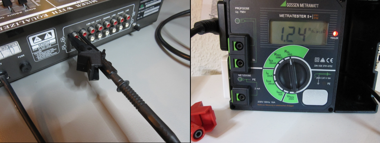
The Secutest Pro gives you two possibilities: The "Red Ring" is for one of several automatic test sequences such as the EN62368 for instance with saved limits, here: less than 100mOhm. When the result is above the limit and therefore not shown in green but red, you have to abort the test and cannot go any further (if you want to pay an extra sum, GMC sells you the ability to bypass this, to go any further). I could change the limit, to bypass this, but does not want to, as it is not save and correct to do so...
However, the "Green Ring" is the manual test of the Secutest Pro, which can be compared with the "Metratester 5+" itself. No measured value is coloured in "green" or "red", but simply "white" and you have to estimate the result on your own or whether you want to test any further...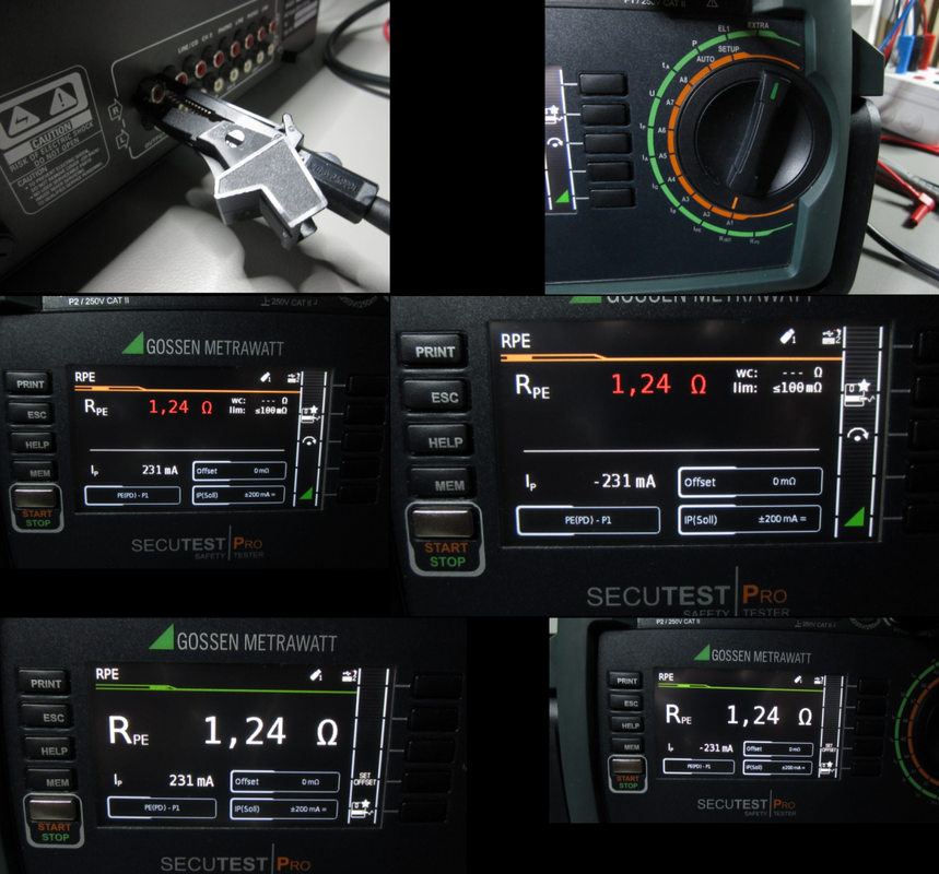
There are special European Norms for testing Audio-Equipment EN62368 and EN62911 (production line) together with the known EN50678 (after repair) and EN50699 (recurrent tests):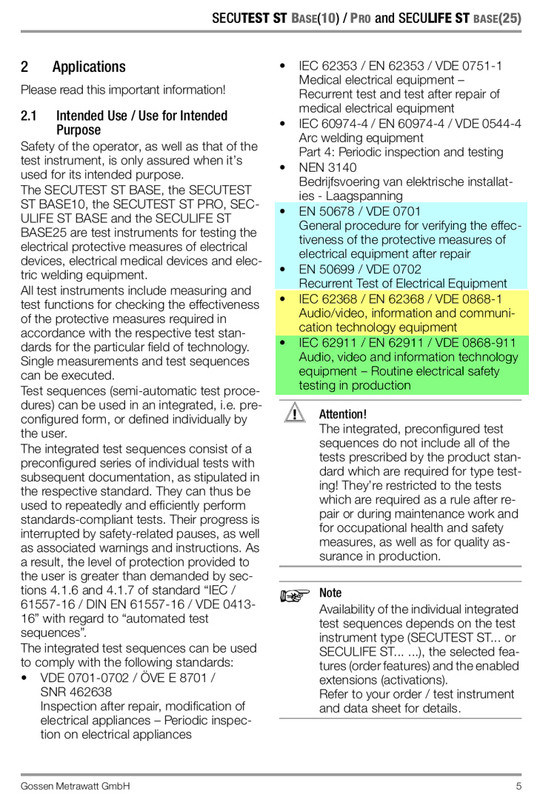
The "Gossen Metrawatt Metratester 5+" is simple to use and has all you need. I was also able to play with a Fluke 6500-2 (therefore I know the differences to the Fluke 6200-2), I owned a "Benning ST 725" (which is and has several clones), which I sold a month ago and finally bought a used "Gossen Metrawatt Secutest Pro" for my private use, as I love testgear...
PS and only as a short note: My "Secutest Pro" has a successor called "Secutest ST Pro", with the newest "European Norms" already included, but as I paid for the update "EN50678/EN50699/EN62368/EN62911" to also use automatic sequences, mine is now identical to the ST-Version, so that I only refer to my unit, as there are too many other things to consider with locked and unlocked Firmware-Features as mentioned above to bypass a negative test for example...
However, the most important things are:
1. different countries may have different limiting values, allthough the test equipment is the same brand and model
2. some pat testers have no automatic test sequence (Metratester 5+) and other units have both possibilities (Secutest Pro)
3. some pat testers can only measure with 500V (Fluke 6200-2), but other units are also able to measure with 250V (Fluke 6500-2, Benning ST 725) or the way you want from 50V to 500V (Secutest Pro), to treat sensitive components with care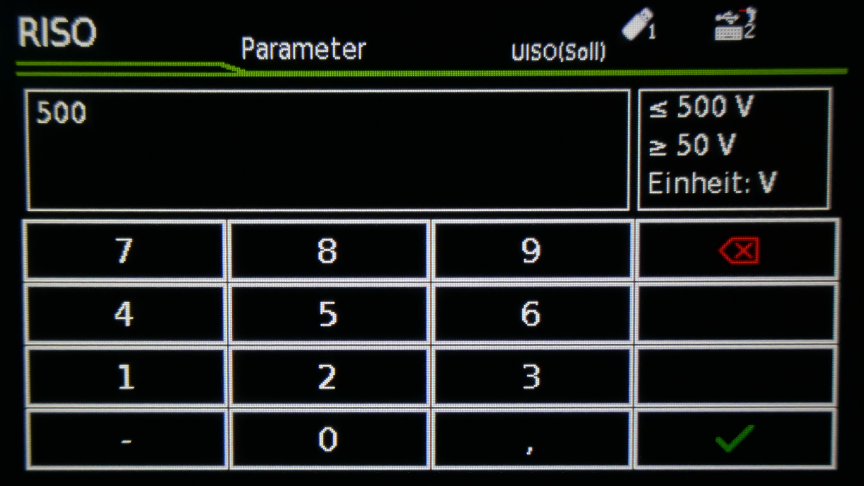
4. any pat tester has to measure with at least +200mA (Benning ST 725), but only some units are also able to measure with 10A (Fluke 6200-2, Fluke 6500-2) and some are also able to measure with +200mADC, -200mADC, +/-200mADC, 200mAAC and 10AAC (Secutest Pro)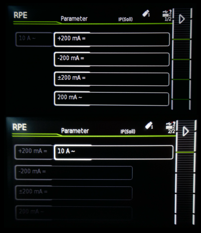
5. some units have no internal clock (Fluke 6200-2), others have (Benning ST 725) and other units even have a build in database to save and document any measurement for later usage and documentation with time and date and serial number of any equipment and so on... (Fluke 6500-2, Secutest Pro)
6. with an additional piece of software IZYTRON.IQ, you can even build your own personal test sequence the way you like (Secutest Pro)
Cheers!
-
As my DJMixer is +30 years old, I was surprised, that the power cord with its poor quality, togteher with a bad earthing point, was the reason for the bad PE resistance test. After solving these issues, I can now show the rest of the EN62368 testing procedure, since the value is now smaller than 100mOhm...
Manual measurement of R PE - showing no limit: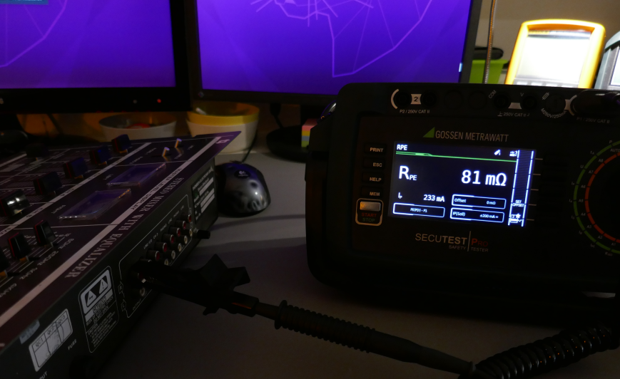
..., before starting the auto test sequence EN62368, so that you know, that it will most likely succeed...
R PE - now with limit: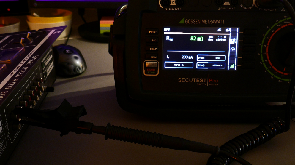
I PE AC NL & DC NL: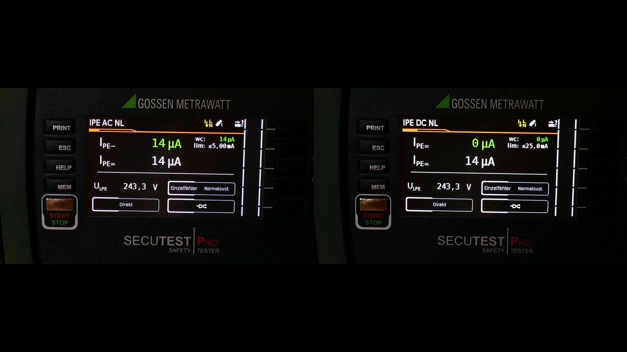
I PE AC LN & DC LN: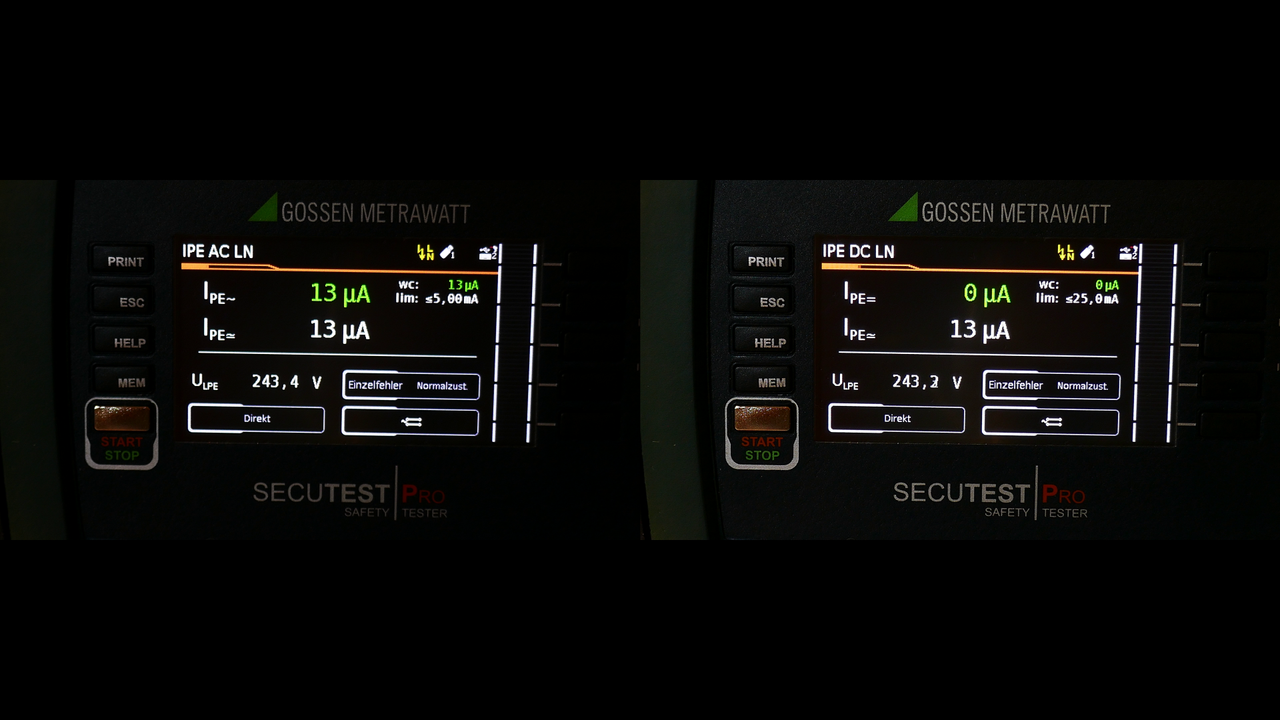
Function test: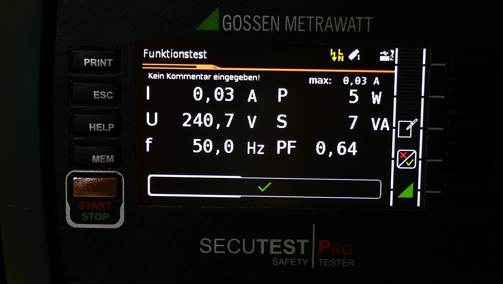
Summary of the result: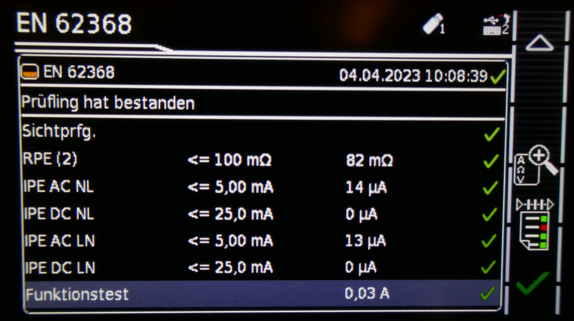
Cheers!
-
Thank you PushUp

Very informative post.
However, I'm afraid that all the recommended options are a bit out of my budget for the time being....
I keep looking for a decent and more affordable solution though. -
Yes, money is always the decisive factor! However, even more important is the wording: Don't save at the wrong end! "In german we say: Nicht am verkehrten Ende sparen!"
My example: As I wanted to save money I bought the cheap ZD-915 desoldering station from a german reseller for about 80 Euro. You cannot expect any build quality for this price, BUT you should at least expect promised material with 0.75mm² copper inside, to ensure safety. I have never ever seen such a bad PE resistance for such a short length of power cord shipped with this package...
With this power cable it is impossible to pass any test and this does prove, that any sticker, which should guarantee safety is bullshit! The cable is marked 0.75mm², but this cannot be the case with 315mOhm: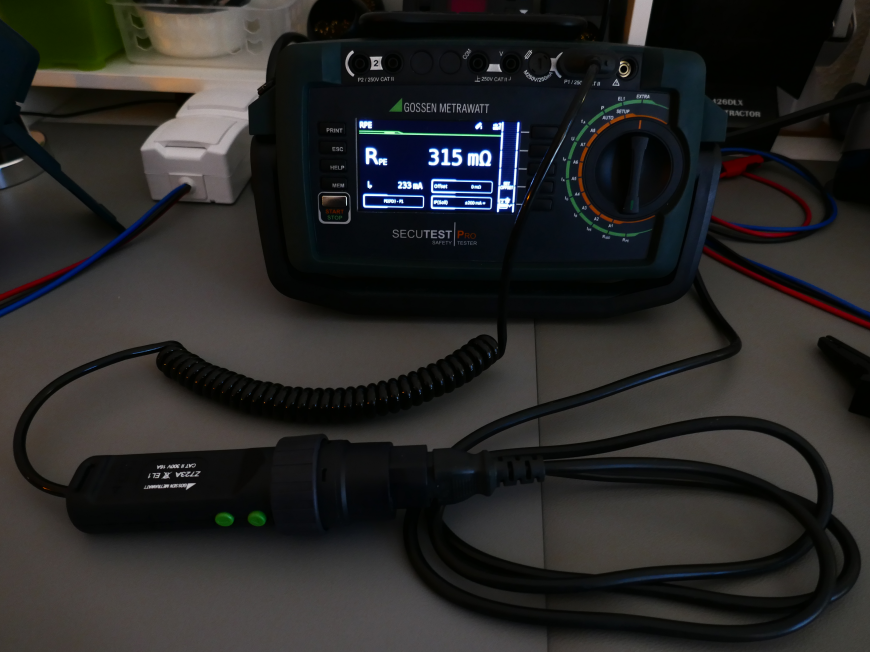
When something goes wrong, it is always a chain of unhappy circumstances, but when it happens, you would like to be on the safe side!
This power cord is from my Weller Solder Station and has the same length and thickness, but only 72mOhm: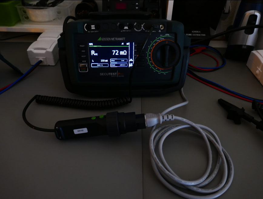
A cheaper possibility to be on the safe side, is to use an Insulation Tester. However, this testgear measures with +300mA (here: 312,1mA) in the low Ohm setting, so that I don't know, if this is still OK, when it comes to a problem or an accident with your audio equipment: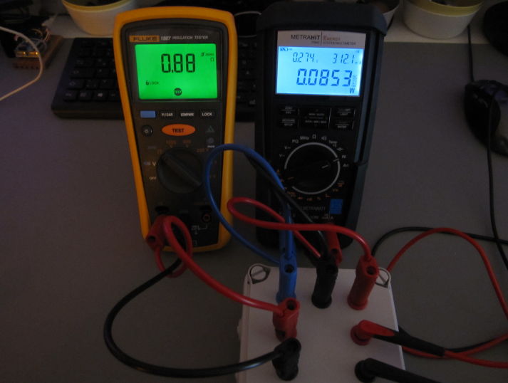
My piece of copper is so thick, that is has a good connection inside the plug and does not play any role as I wiggled around to get a good connection point. Compared to the 315mOhm from above 320mOhm is a good hint, that the values are at least plausible and therefore right: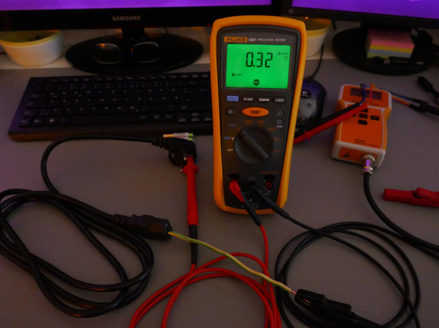
...and just as a comparison, that it is always better to build your own power cables with 1.5mm² thickness: This testing cable is 6m long, has a switch, a power outlet, 1m long testleads and several wago inside, together with the usual spring connection points and has only 74mOhm: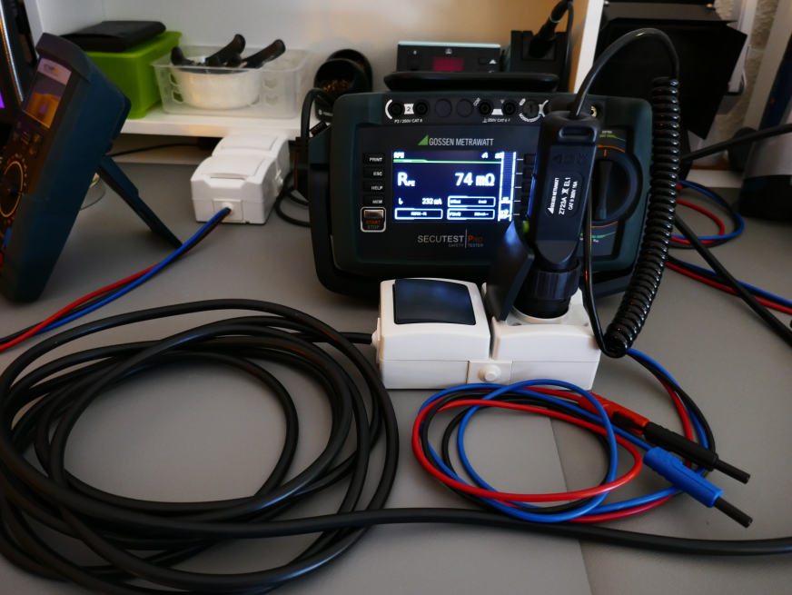
Cheers!
-
With this power cable it is impossible to pass any test and this does prove, that any sticker, which should guarantee safety is bullshit! The cable is marked 0.75mm², but this cannot be the case with 315mOhm:
So it is 0.75mm² or not ? Measuring resistance of the cable and calculating resistivity of copper, but what if it is aluminium or iron or other cheaper metal, but still 0.75mm² ? -
As long as the measured values are within its limit, it is fine, which is obviously not the case in my example. Some pat tester such as my already sold "Benning ST 725", gives you even a hint, when you measure PE resistance of a cable (it is the same cable from my desoldering station, as I keep it as a bad example) and you are over 300mOhm (here: 320mOhm, by the way it is the same value as shown by the Fluke 1507): in this case "table" means, that there is something totally wrong...
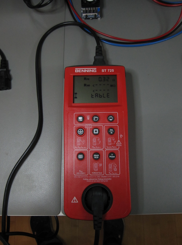
...and you should check the list of values, as there are no exceptions allowed, when you want to be on the safe side, because 300mOhm is the limit and worst scenario, which means, that you always and forever have to be way under this value and should not pass 150mOhm in the extreme case: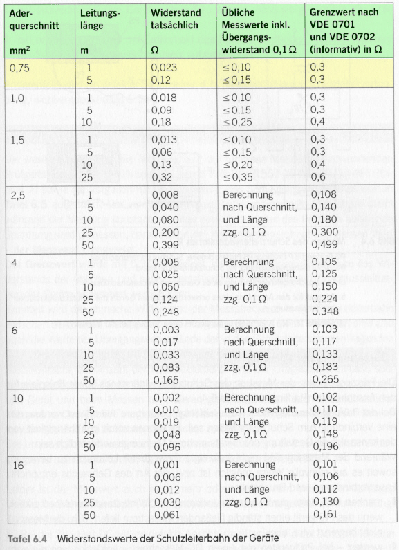
When length and thickness would also give a good value and they are within its limit, the producer will obviously choose the cheapest possible material.
However, as far as my measurements are concerned, most chinese producer even don't pay attention to safety issues and when your house burns down due to overheating, it is your problem, as long as you or your family will survive the fire.
My example and measurements do prove, that this becomes totally normal, so that it is up to you, to check any cable and/or testgear before using it - the safeyt stickers are useless and that is why I wrote in my first post, that anybody should have or at least use a pat tester!
This cable, for instance, was from my first 15 Inch Eizo Monitor and I have never ever seen such a good value of 50mOhm anymore, which underlines my observation...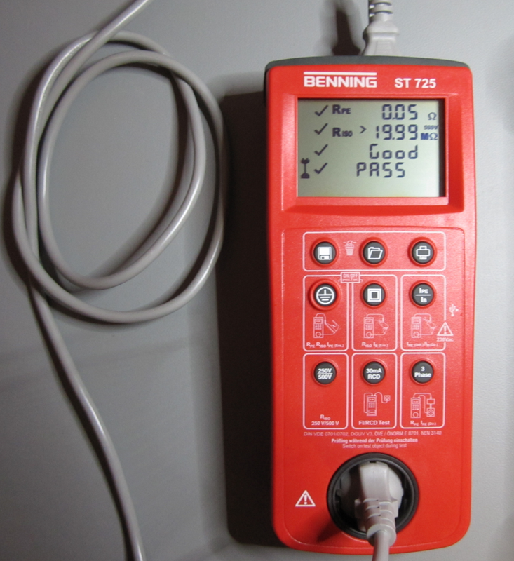
Cheers!
-
I have always been using a Gossen Metrawatt Secutest for my VDE 701/702 requirements.
Nice to see some other instruments here for the same purpose.
Thanks for the many pictures.