-
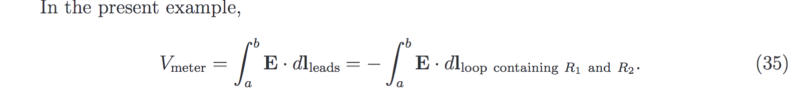
I have been, and I have to admit I'm quite perplexed with it. In particular equation 35 doesn't seem correct to me. For example, if we assume a point in time where I = 1mA, R1 = 100ohm, R2 = 900ohm, R = 1Mohm and I1 ≈ 0 (as he states) then he seems to be saying 0V = -1V. If someone can help clear this up for me I'd appreciate it.
[Edit 1: fix typos]
I agree equation 35 does not look correct, maybe it is a typo. He seems to have left out the EMF term. Perhaps by E he is refering to EV as in equation 18. -
I agree equation 35 does not look correct, maybe it is a typo. He seems to have left out the EMF term.
It's not a crime and it does not make it a typo. Dr.Lewin omits EMF vector potential terms all the time. Everybody does. Even mhz himself: -
Int E•dl in the wires is 0V (no E fields in perfect conductors, or next to none in real conductors in which case we approximate to 0) and in the resistor is equivalent to I*R (if not then what do you think the contribution of Int E•dl through the resistor is?).
Faradays law? ... Maybe? From your blog BTW:
That is Faraday's law yes, how would you use it to calculate the contribution of the line integral of E•dl through the resistor?QuoteYour response contradicts several of the things McDonald says in his paper, namely that the voltmeter will read 0V (not 0.125V) and that I1 = 0 is misleading/incorrect. So now who should I believe, you or McDonald?
Anybody else wanna take a crack at this?QuoteI do not contradict with McDonald. You do. I will repeat again what he says: "the result Vmeter = 0 is appealing in that we might naïvely expect the “voltage drop” to be zero between points along a good/perfect conductor." He even shows equation (34) how to calculate voltage between a-b points.
You said "Voltmeter shall show 0.125V."
McDonald said "the result Vmeter = 0 ..."
I believe what you meant to say is that Vab = 0.125V (based on your use of equation 34), despite the fact that the Voltmeter shows 0V.
At any rate, I'm asking about equation 35 not 34*. You're fixating on the arc a-b when equation 35 doesn't include that arc in either of its path integrals (as shown in my color coded annotation).
I asked a question in the previous post. "what do you think the contribution of Int E•dl through the resistor is?" You seemed to disagree with me that it is equal to I*R.
*admittedly, equation 34 is confusing to me as well but I suspect I'm not going to follow McDonald there without a much deeper reading of this paper, rather than having it explained to me here.
Edit1: attempt at fix quotesing -
That is Faraday's law yes, how would you use it to calculate the contribution of the line integral of E•dl through the resistor?
Why you suddenly introduce resistor here? We talk about Maxwell's equations and Faradays law. Note that wire segment a-b does not contain any resistor.QuoteYou said "Voltmeter shall show 0.125V."
Yes. I demonstrated you how to calculate voltage between a-b in case angle is 45 degrees. McDonald provides only formula, not actual calculation. Where's your problem to understand that?QuoteMcDonald said "the result Vmeter = 0 ..."
If you cannot comprehend that McDonald says that it is naïve to expect that voltmeter will show 0V, then our discussion is finished here and now. When you confirm that you can read - we may continue.
-
That is Faraday's law yes, how would you use it to calculate the contribution of the line integral of E•dl through the resistor?
Why you suddenly introduce resistor here? We talk about Maxwell's equations and Faradays law. Note that wire segment a-b does not contain any resistor.
I didn't suddenly introduce it. It's inside one of the path integrals in equation 35 which is what I've been talking with you about for these past several posts. I now see that you were still referring to the arc a-b and using equation 34 when you said "Oh, my... You use Ohms law to claim that voltage between a-b is 1V? "
"
I'm fully able to plug the same numbers into equation 34 as you are. You keep responding to my questions about equation 35 with equation 34. I've already conceded that I don't understand McDonald's development to arriving at that equation, and I'm not particularly interested in discussing it here without a chance to do a deeper read of his paper. I have been talking about equation 35 for these past several posts and it's now clear that you've been ignoring them and persisting at talking about equation 34. We're not even talking about the same thing.QuoteQuoteYou said "Voltmeter shall show 0.125V."
Yes. I demonstrated you how to calculate voltage between a-b in case angle is 45 degrees. McDonald provides only formula, not actual calculation. Where's your problem to understand that?QuoteMcDonald said "the result Vmeter = 0 ..."
If you cannot comprehend that McDonald says that it is naïve to expect that voltmeter will show 0V, then our discussion is finished here and now. When you confirm that you can read - we may continue.
"our discussion is finished here and now"
Sounds good to me.
-
I didn't suddenly introduce it. It's inside one of the path integrals in equation 35 which is what I've been talking with you about for these past several posts. I now see that you were still referring to the arc a-b and using equation 34 when you said "Oh, my... You use Ohms law to claim that voltage between a-b is 1V?
"
I'm fully able to plug the same numbers into equation 34 as you are. You keep responding to my questions about equation 35 with equation 34.
Equation 34 is derivative of equation 35. They essentially both are explaining EMF voltage at given time of observation between points a & b. Thou there's enough data only for equation 34 to calculate anything. Note that Dr.Lewin also declares "EMF equals 1V" and do not actually calculate it (EMF voltage) using Maxwell's equation. So your questions about equation 35 and field inside resistors when it is defined that EMF is 1V and current flowing in the loop 1mA is... kinda pointless. You shall go straight to equation 34 and calculate it - as I did it already. Result was not 0V.
[edit] BTW integral E.dl between points a & b does not have resistor in the path, your equation is incorrect in result:"QuoteI have been talking about equation 35 for these past several posts and it's now clear that you've been ignoring them and persisting at talking about equation 34. We're not even talking about the same thing.
It is clear that you did not even understand that those two are essentially the same Quote
Quote"our discussion is finished here and now"
Sounds good to me.
I am glad that we can agree at least about something.
-
To not repeat a certain arrangement i will also answer this for both definitions of voltage:
A) For definition "Voltage is the integral of all forces pushing on electrons along a given path connecting two points":
The inductors L2 L3 L4 L5 have zero voltage across them at all times (Zero resistance). Any EMF voltage induced in the wire by the magnetic field is instantly countered by the charge separation of electrons.
B) For definition "Voltage is the difference in charge density between two points" (This is what real life voltmeters show)
The inductors L2 L3 L4 L5 have a voltage drop that sums up to the same voltage as the total voltage drop on the resistors. This voltage in the wire is caused by charge separation pushing electrons towards one end of a wire, resulting in more electrons on one end hence higher voltage on one end.
Thank you for very good explanation of vector versus scalar potentials. I admire your patience explaining underlying basics to those who learn physics just by memorizing equations. -
Where does definition B come from? Charge density and Voltage don't even have the same units. [C/m3] vs [J/C]
Yes the units don't quite match up because they are not the same thing.
It comes from removing the effects of external fields. As you have seen in this thread circuit meshes don't handle external fields. The components that make up a mesh model act as if they have zero physical size (This includes all wires being 0m long). This means that no matter how strong a magnetic or electric field the circuit is exposed for there will never be any observable field gradient across a component. A loop with a area of 0 m2 can't have EMF induced in it no matter what you do.
So when external fields have no effects the only thing remaining pushing electrons around is the internal electric field caused by charge separation and this is basically different charge density between two points.
This section of the Wiki page for voltage explains the conflicting definitions:
https://en.wikipedia.org/wiki/Voltage#Definition
The kind of voltage i am talking about in definition (B) is what they call "Definition via decomposition of electric field". You can read up on the details by flowing the links. It uses a different way of treating the magnetic field to make charge separation via EMF visible as a voltage. This solves all the multiple result ambiguities of definition (A) and always gives a single number for every point in the circuit. By doing this it also causes a voltage to appear on a wire when in a changing magnetic field.
This is the source of argument for most of the recent posts in this thread. The answer to the above diagrams depends on what definition you are using.I disagree. You can split the total mutual inductance M of the loop into two strings of as many inductors as you want in spice. The value you measure in spice will not be the actual scalar voltage potential between the ends of the resistors (which is approximately zero as measured by the voltmeter). Lumping can't be done in this kind of circuit in spice without creating false outcomes.
Well i was comparing my spice simulation results to experimental data made on youtube and on my own bench, they seamed to match pretty closely. So it does appear to work fine for circuits discussed here. If it is wrong then it looks like it takes a different or more complex circuit to cause it to break. Lumping is very commonly used even in RF circuits, its just a matter of lumping it correctly.
Do note that SPICE like all other circuit analysis uses the second definition (B) for voltage. The equation used for that is seen on the Wiki article above.I see now that you're trying to model the mutual inductance of the "outer loop" i.e. the path formed by the two measurement loops, but not going through R1 and R2. You've arranged the coupling dots in a way that the inner inductors and outer inductors cancel each other out in a way that satisfies there being no flux coupling in the two measurement loops.
Yes the coupling dots are very important. The dots indicate that both loops are going clockwise around the center. So if you go around the loop you will always see them pointing the same way. If the dot points the other way that would signify the wire turning around and going counterclockwise, its allowed to do that if it wants and will still give correct results, however this circuit does not have the wire changing direction around the loop so they all point the same direction.
You have indeed identified correctly how this model works. Because the wire going to the resistor and the wire going to the voltmeter flow the same path this means they get the same voltage induced in them. Since you need to go clockwise to get to the circle midpoint and then back counterclockwise to get back to the meter the voltages are opposite in sign and they subtract out. This is called bifilar winding and is widely used for removing inductance when its not desired.
If you use the second definition (B) of voltage and as described in the Wiki article use the "magnetic vector potential" to think about the magnetic field you will find the exact same behavior in the real life circuit.
Its just a different way of thinking about it. Results are identical in the end, just how you get to them is slightly different. -
Is it still OK to use a voltmeter? Or is every measurement suspect now?
-
I disagree with the thread title.
Walter Lewin used to be a master. Then he started flinging poo at good people.
So i vote we take Master status from him.
A mark of distinction of those who criticize Lewin is their utter and declared inability to teach Maxwell.
-
A mark of distinction of those who criticize Lewin is their utter and declared inability to teach Maxwell.
To be fair, he did issue an apology video. Don't know if it's already been linked to here.
-
Is it still OK to use a voltmeter? Or is every measurement suspect now?
It depends. Definitely you shall know what you are doing and how exactly your voltmeter measure voltages and how it may impact results. Sometimes you may want to use electrometer instead of voltmeter. -
Is it still OK to use a voltmeter? Or is every measurement suspect now?
Those meter measurements were always suspect in certain situations.
-
To be fair, he did issue an apology video. Don't know if it's already been linked to here.
Yes it was mentioned here "many pages of posts" ago. Dr.Lewin is one of greatest physics teachers known, he deserves all the titles received.
Punishment shall be proportionate. MIT may revoke his emeritus title, harassed women may seek justice in the court, but come on - removing all his life's work, his courses and lectures from all MIT teaching platforms is way too much. MIT punished not only Dr.Lewin but many, many students. Luckily we have youtube and hopefully social justice warriors of MIT will not do anything about it. We shall not burn scientist with all his books/works/videos just because he made some mistake in his life. -
Is it still OK to use a voltmeter? Or is every measurement suspect now?
Those meter measurements were always suspect in certain situations.
During lightning storms, I guess... -
Is it still OK to use a voltmeter?
That's a very good question. And trying to answer it is the path to understanding Maxwell and his dreaded equations.QuoteOr is every measurement suspect now?
Why would Nature lie to you? -
Regarding McDonalds 'paper' (has that been published on a peer reviewed paper?), let me quote this comment George Hnatiuk from a youtube discussion
QuoteI found several errors in the "Lewin's Circuit Paradox" paper back in June to which I alerted Dirk and company and the paper has since been edited with NEW errors introduced and some of the older ones still present. It is very sloppy work at best and nothing I would expect from a university staff member.
Ok. Fair enough. Nobody's perfect. That's why peer review practice is so important and McDonald do error corrections. Could you provide (link to) Dr.Lewin's paper regarding subject, supposedly peer-reviewed?QuoteAs I said before, you should try to analyze how the lumped circuit simplifications come about before tackling non-lumped circuits like Lewin's ring.
As I said - when you read McDonald's paper you will see that Dr.Lewin's circuit can be analyzed as circuit of lumped elements. If you disagree, then prove opposite - tell where and how McDonald is wrong. [edit] Robert H. Romer in his paper do lumped analysis as well BTW.
-
EMF source equation alone does not describe system of EMF source *and* load. In the inner loop of Dr.Lewin's experiment E fields can be expressed as E = E.coloumb + E.induced. Wire loop is responsible for E.induced, we can say it is EMF source. As resistance of the wire is very small compared to resistors we ignore it so all the E.coloumb field is located in the resistors - those are load. In Laymans terms: EMF generated by the wire is dissipated in the resistors. Now question - what's the summary field (integral E.dl ) of the loop E = E.coloumb + E.induced? Before you answer remember energy conservation law - that all the energy generated by wire loop is dissipated in the resistors.
-
Ok. Fair enough. Nobody's perfect. That's why peer review practice is so important and McDonald do error corrections. Could you provide (link to) Dr.Lewin's paper regarding subject, supposedly peer-reviewed?
Why, it's Romer's paper - it's funny you did not realize it, considering you are mentioning it in this very post. I can even cite a book that has the very same analysis - I mean literally quotes Romer - but I'll keep that to myself for the moment. You would not read it anyway, like you did not read Ramo Whinnery Van Duzer.QuoteAs I said - when you read McDonald's paper you will see that Dr.Lewin's circuit can be analyzed as circuit of lumped elements. If you disagree, then prove opposite - tell where and how McDonald is wrong.
Maybe you are misunderstanding McDonald as well.QuoteIn the inner loop of Dr.Lewin's experiment E fields can be expressed as E = E.coloumb + E.induced. Wire loop is responsible for E.induced, we can say it is EMF source. As resistance of the wire is very small compared to resistors we ignore it so all the E.coloumb field is located in the resistors - those are load.
Nah, the *resulting* field is all located in the resistor. E_coulomb kills E_induced in the wires giving a resultant E field compatible with j = sigma E.
-
Why, it's Romer's paper - it's funny you did not realize it
It's not. Dr.Lewin's lecture(s) do not follow Romer's paper by any stretch of imagination, you shall know it (maybe). Are you absolutely sure you want to go down this rabbit hole? QuoteQuote
As I said - when you read McDonald's paper you will see that Dr.Lewin's circuit can be analyzed as circuit of lumped elements. If you disagree, then prove opposite - tell where and how McDonald is wrong.
Maybe you are misunderstanding McDonald as well.
Instead of pointing out where McDonald is wrong you come-up with this BS? BTW John W. Belcher in his paper do lumped analysis as well.QuoteE_coulomb kills E_induced in the wires
Right. In short:itsum is zero. End of discussion.
-
Romer's paper is about the very same experiment made by Lewin, and it reaches the very same conclusions.
How is that? I do not find Romer mentioning birds in his conclusions. Do you mean conclusion "Faraday's law is very fascinating and puzzling"? Yes, they both are puzzled about Faraday's law - We all are. Especially when it is interpreted by Dr.Lewin. Ok, kidding. L(di/dt) is not that puzzling and it works well. Please name those "very same conclusions" you are talking about. I am excited to hear them.QuoteSo, since real life voltmeters have (to my knowledge) no way to tell the E_coulomb and the E_induced apart but only see the effect of the resulting total field, it makes little sense to ascribe to the [difference in the values of the] scalar potential any meaning besides that of the voltage measured along a very special class of paths.
TL;DR. Are you suggesting that voltmeter can be used to measure electric field? Question did not mention voltmeters, nor expected voltage as an answer: "what's the summary field (integral E.dl ) of the loop E = E.coloumb + E.induced?" You did not gave clear answer. Is it zero or not?
p.s. Of course all electrons are the same, no matter they were moved by electromagnetic induction, chemical reaction or just static electricity.
p.p.s Yes, I am sarcastic - because when I ask you simple question, you are making evasive moves like scammer who is caught. -
And he didn't start with "Hello, hello, hello!" as well. Then they must have found completely different results.
As an argument I was referring to scientific paper having peer review and corrections. All you have in return is youtube video with introduction "Hello, hello, hello", no written content and no peer review? Whatta crooked mirrors world you are living in?!QuoteWhat I see is that they both find that the voltage is dependent on the path, and that when placed on the outside of the loop the voltmeters - applied to the very same two points - give different and opposite phase reading.
What?!! Your whole proof is two voltmeters showing different signs?QuoteQuote"what's the summary field (integral E.dl ) of the loop E = E.coloumb + E.induced?" You did not gave clear answer. Is it zero or not?
Here's the answer, assuming that with 'summary' you mean circulation along the circuit's path: the circulation of E_total (integral of (E_coloumb + E_induced) . dl along the circuit's path is equal to minus the time derivative of the flux of B linked by said path.
Yes, it's Faraday's law.
So you refuse to name number because you either do not know it of refuse to acknowledge it being zero? -
Please do yourself and anybody else a favor: get hold of a copy of "Fields and Waves in Communication Electronics" by Ramo, Whinnery and VanDuzer and read the first four pages of chapter 4 (The electromagnetics of circuits)...
I guess you really like that book. It was my textbook in college 37 years ago for "Electromagnetic Fields and Waves" EECS117A, B, and C. The teacher was Theodore Van Duzer.
Gee, that was before Dr. Lewin first performed his SUPER DEMO. My education was lacking. -
To be fair, he did issue an apology video. Don't know if it's already been linked to here.
Yes it was mentioned here "many pages of posts" ago. Dr.Lewin is one of greatest physics teachers known, he deserves all the titles received.
Punishment shall be proportionate. MIT may revoke his emeritus title, harassed women may seek justice in the court, but come on - removing all his life's work, his courses and lectures from all MIT teaching platforms is way too much. MIT punished not only Dr.Lewin but many, many students. Luckily we have youtube and hopefully social justice warriors of MIT will not do anything about it. We shall not burn scientist with all his books/works/videos just because he made some mistake in his life.
Woah
What happened here?
Was he involved in some sexual scandal or something?
Edit?: found it:
https://www.insidehighered.com/news/2015/01/23/complainant-unprecedented-walter-lewin-sexual-harassment-case-comes-forward
I didn't know they removed all his lectures from their openMIT channel
-
Was he involved in some sexual scandal or something?
He became of #metoo target, due to his own human error. As I already said - I do not agree. Such issues shall be resolved in/by court, not by directorate of MIT - by literally burning all his work, by punishing his students, not actually punishing himself. [edit] AFAIK it was by consent - hot pics in exchange for passed exams.