-
Now got this into a cookie box and the results are quite good: noisefloor improved by a factor ~2 down to ~115nVpp/10min (there is no difference between input shorted and 33mF cap @8V)
The noise floor with input shorted and circuit turned off is <50nVpp, scope distributes ~35nVpp.
This means a third of noisefloor is not from circuit - perhaps worth checking with DMM @ <= 0.01 PLCs and accurate to <<0.1mV?
For input I salvaged CAT5 patch cable and put together each 4 from different pairs - this should be quite good for shielding electric and magnetic fields and is flexible.
The shield is directly soldered to input low and cookie box, output BNC is isolated from shield/cookie box to omit ground loop (recommend this article about shielding/guarding)
The cookie box should be tinplate as used in hf-circuits, as it shields electric and magnetic fields and is solderable (other metals like copper or alu do not shield [LF] magnetic fields quite good).
It's time to get serious, but for now other projects are demanding
First need to get bigger cookie box for putting measured circuit and noiseamp together and apply holes for the cables...
Here are a couple of measurements, as it turned out a 9V block is really noisy (~4,8µVpp) in comparison with 8x mignon ready to use (~200nVpp):
-
Hello,
I got my hands on one of Pipelie's LNA's and made some measurements of some LTZ1000's.
I did a more in-depth write-up here: https://github.com/cellularmitosis/logs/blob/master/20180324-ltz1000-1f-noise/README.md
I had a question about loading the LTZ circuit. When discharged, the 1000uF input capacitor in the LNA appears as a 2k load to the LTZ, which would initially draw 3.5mA (decreasing to 1mA after about 3 seconds). Is it safe to draw this current from an LTZ? My intuition says yes, because a zener regulates a load by diverting current away from itself, so there is actually 3.5mA less current flowing through the LTZ during this period.
A variation on that question: if the LTZ nominally has about 4mA flowing through it, would there be any adverse effects of attempting to draw more than 4mA from the circuit?
Edit: initially my noise floor wasn't usable. using my aluminum dutch oven trick solved that.
-
Hello,
my intuition says draw not more than 2mA from a unbuffered LTZ.
Since the current regulation loop will need some time to step up.
By the way: the 2K are not the only path where a current can flow.
(So did you really measure the current?)
There is a 510 Ohms via a diode to UBAT (3.7V) to protect the input of the amplifier.
Fortunately there are no clamping diodes between the inputs of the ADA4528.
(otherwise there would be a addinonal path with around 1K to ground).
I have aged my unbuffered LTZs several times by transient pulses where the static load is below 2 mA.
I always use 3K6 in series while charging the input capacitor of my LNA.
If you want to try it: keep an eye on the heater output voltage (with the scope).
Or alternatively to the temperature setpoint. (carefully).
with best regards
Andreas
-
@cellular,
don't believe you have such a bunch of LTZ's now.
Your measurements are very interesting.
Would you plan to measure some buffered ones, maybe TEKO used? Don't have one of this LNA's in the moment.
I see, you took some Genrad tempco measurements with selfmade copper wire compensation resistors with promising results too. Awesome
-
Hello,
I got my hands on one of Pipelie's LNA's and made some measurements of some LTZ1000's.
I did a more in-depth write-up here: https://github.com/cellularmitosis/logs/blob/master/20180324-ltz1000-1f-noise/README.md
I had a question about loading the LTZ circuit. When discharged, the 1000uF input capacitor in the LNA appears as a 2k load to the LTZ, which would initially draw 3.5mA (decreasing to 1mA after about 3 seconds). Is it safe to draw this current from an LTZ? My intuition says yes, because a zener regulates a load by diverting current away from itself, so there is actually 3.5mA less current flowing through the LTZ during this period.
A variation on that question: if the LTZ nominally has about 4mA flowing through it, would there be any adverse effects of attempting to draw more than 4mA from the circuit?
Edit: initially my noise floor wasn't usable. using my aluminum dutch oven trick solved that.
Thanks for sharing the test result of the noise performance of LTZs.
and BTW, when testing unbuffered LTZ, it's wise to use your power supply to charge the input Capacitor to 7V (or equal to the voltage of LTZ) before you connect the LNA to your unbuffered LTZ.
-
I had a question about loading the LTZ circuit. When discharged, the 1000uF input capacitor in the LNA appears as a 2k load to the LTZ, which would initially draw 3.5mA (decreasing to 1mA after about 3 seconds). Is it safe to draw this current from an LTZ?
I think you can't draw current from LTZ, but you will draw current from the amplifier ( LT1013). and it won't damage the lt1013 or LTZ, and you have to wait much longer until LTZ Circuits stabilize from “heavy current output” situation. -
Ill add a 10v Buffered LTZ1000A to this thread,
0.1x prob setting with 10,000x gain LNA. So divide the displayed voltage by 1,000. Here, 1.8uV P-P or 307nV RMS over 14 seconds.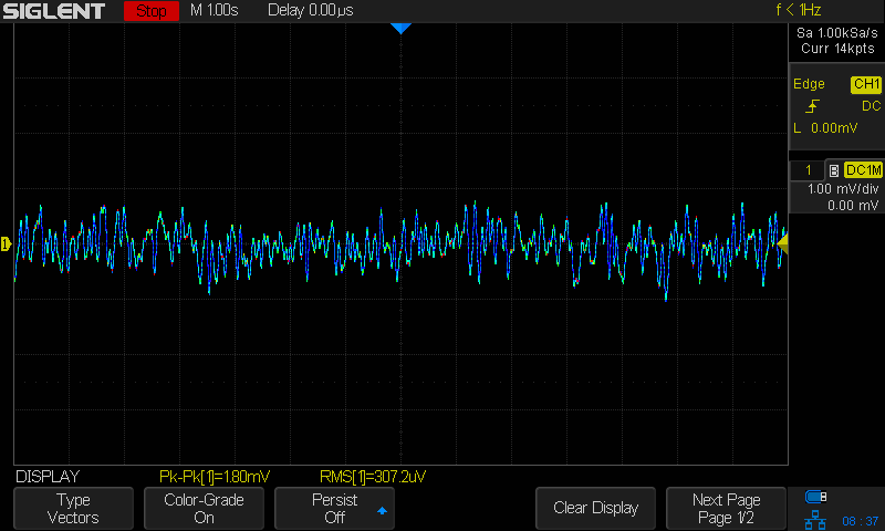
Noise floor with the reference powered off, 220nV P-P or 94nV RMS;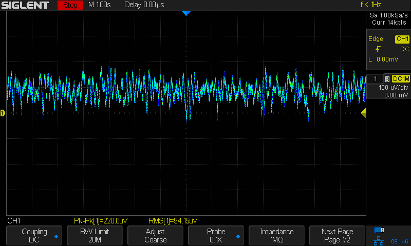
The setup;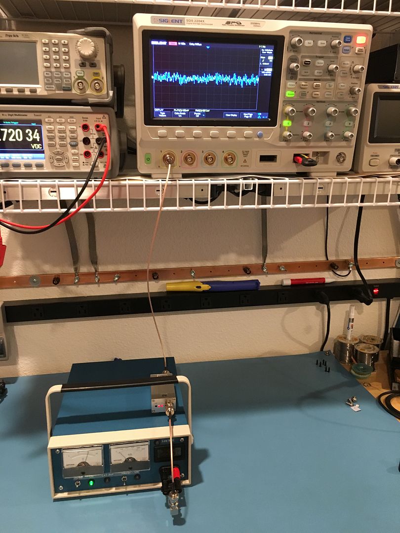
-
and it won't damage the lt1013 or LTZ,
Hello,
I would not sign that.
If you draw too much current out of the unbuffered reference the temperature setpoint goes to infinite.
The heater of the LTZ will cook the reference -> quickly ageing and a much larger drift for the next ~6 months.
I tried this accidently several times on my unbuffered references.
The last events where LTZ#1 by -2ppm at day 860 and
LTZ#2 by -5 ppm at day 1220.
with best regards
Andreas
-
I wonder if we can engineer some diode clamping to limit the max heater set-point?
-
One could definitely add some protection to the heater. A simple one could use something like a divider on the output and a TL431 to check if the voltage is in a reasonable range before enabling the heater.
Another option would be just to limit the power to the heater - this might limit the lower temperature range a little (but who cares about sub zero environment) and make the warm up a few seconds slower.
Both cases would not be a perfect protection, but it should limit possible damage. -
Just a quick note.
With an LTZ1000A device and 15V on the collector of the heater transistor, the chip could heat up 300 deg C above ambient, worst case. If the heater transistor collector voltage is limited to 8V the worst case temperature rise is approximately 80 deg C above ambient. The actual temperature rise will depend on heater resistance, length of LTZ leads, PCB trace size, local airflow and several other things. A small Zener in series with the heater transistor collector can go a long way to prevent damage to the expensive chip.
The LTZ1000 chip does not get that hot because it has better heat conduction between the chip and the case.
I usually run a separate power supply for the heater transistor until I'm finished developing a circuit. -
Just a quick note.
With an LTZ1000A device and 15V on the collector of the heater transistor, the chip could heat up 300 deg C above ambient, worst case. If the heater transistor collector voltage is limited to 8V the worst case temperature rise is approximately 80 deg C above ambient. The actual temperature rise will depend on heater resistance, length of LTZ leads, PCB trace size, local airflow and several other things. A small Zener in series with the heater transistor collector can go a long way to prevent damage to the expensive chip.
The LTZ1000 chip does not get that hot because it has better heat conduction between the chip and the case.
I usually run a separate power supply for the heater transistor until I'm finished developing a circuit.
if the 15V was applied to the output of LTZ long enough, it will destroy the LTZ. that happens on my 4950, did I mention it before?
anyway, the cause of this is the tantalum on 15V power rail short, and the Analog switch that shares the same 15V damage(short between the power supply and channel) because Of that, and the 15V go through the switch and apply to the LTZ's 7V Hi. eventually, the heater is broken and short.
so, before you connect your LTZ to LNA, it's better to measure the voltage of the input Capacitor first, if you aren't sure about that. -
A small Zener in series with the heater transistor collector can go a long way to prevent damage to the expensive chip.
turns out adding that little zener to my board was a good idea after all
-
CM had huge troubles with that little zener
 His LTZ build became good thermometer data instead of <0.05ppm/K reference
  with the zener in heater power rail.
-
CM had huge troubles with that little zener
Do you think, that's not a good idea? -
The possible "trouble" the voltage dropping zener could cause is loss of temperature regulation. No damage to anything.
The possible "trouble" with 15V on the heater transistor can be a broken LTZ device. -
With the non A LTZ1000 chip you probably need to stay with 15V applied to the heater transistor. Even with 160 K/watt thermal resistance and 14V on the heater you will have a maximum of 115 K temperature rise. This should not cause serious damage.
-
It would be a good idea to have the protection adjustable, so that one can adjust the limit to a little more than actually needed (e.g. assume a 10 C minimum environmental temperature).
The thermal resistance depends on the board and cap and the heater resistor as quite a lot of tolerance. -
Hmh,
the discussion reminds me of somewhat like:
Take the blue pain killers when you want to touch the hot end of a 400W soldering iron,
and the white ones to touch the 80W.
I would tell my children: never touch the hot end of a soldering iron.
(and use a buffer instead).
SCNR
Andreas
-
Take the blue pain killers when you want to touch the hot end of a 400W soldering iron,
Those blue pain killers sound awesome. There are days I could use those. -
Hello, I decided to build my own 10K:1 amplifier. It is based on previous designs shared here on EEVBlog with some minor changes I think will be beneficial. I will attach the proposed schematic and PCB layout below for comments and suggestions. I will commit to having the PCBs made in about two weeks, so I have time for revisions. The finished unit is intended to be 9V battery powered and housed in a cast aluminum enclosure roughly 4.7 x 3.5" and 2" deep. The inputs will be banana jacks and the output BNC or SMA. The PCB design accommodates both. Note: I managed to find non-polarized electrolytic capacitors for the 1000uF and 2200uF coupling capacitors (Rubicon I think).
-
I see there is a current limiting resistor R1 and that's great, however if the startup sequence is performed out of order then U1 can be damaged. Back to back diodes across R2 or C5 will help prevent damage to the LT1037 input stage.
Last week I used a K617 to compared the leakage current of 1N4148A diodes with 10V reverse bias and a BAV199 Diode pair with reverse 10V bias. The 1N4148A had 10 na and the BAV199 had 40 fa. So the BAV199 had over 100k times less leakage. They are both 150ma diodes. -
R2 is a rather low value resistor. So the amplifier will have a low input impedance - with some sources this could lead to a reduced amplitude. This includes the case when the R1 for protection is active. In addition R2 would increasethe noise at around the lower frequency range.
From the noise perspective it is better to not have the input RC to set the lower frequency limit, but have this filter function at a later stage, after some amplification.
So except for faster settling there is not match advantage of a low value for R2.
For conditioning it might be a good idea to have a way to apply something like a 9 V battery to the input cap via a high value resistor. It might take quite some time under voltage to get the really lowest noise from electrolytic caps. This could be a real problem with bipolar caps though. So I am not sure they are a good idea.
The filter stage around U2 could be higher impedance in some points. So one could get away with lower capacitance for C12-C14. For a good filter a proper 2nd order active filter should give a better response curve than just a bunch of 1. st order RC combinations. The last filter stage directly at the output is also a problem, as the input impedance of the scope or what ever is connected would influence the bandwidth and gain.
The LT1012 (like other slow non AZ OPs) does not need that much decoupling - 100 nF + 100 µF would be already plenty. The extra decoupling caps make sense only if they are really close to the chip . so with the current layout the extra 33 nF and 100 nF caps at U1 do not help and may do more harm than good.
It might help to have access to the output of U1. This could be used for 2 purposes: check the input current / settling and for use as a wider bandwidth (e.g. 0.02 Hz - 10 kHz) amplifier, e.g. with a scope. -
R2 is a rather low value resistor. So the amplifier will have a low input impedance - with some sources this could lead to a reduced amplitude. This includes the case when the R1 for protection is active. In addition R2 would increasethe noise at around the lower frequency range.
From the noise perspective it is better to not have the input RC to set the lower frequency limit, but have this filter function at a later stage, after some amplification.
So except for faster settling there is not match advantage of a low value for R2.
For conditioning it might be a good idea to have a way to apply something like a 9 V battery to the input cap via a high value resistor. It might take quite some time under voltage to get the really lowest noise from electrolytic caps. This could be a real problem with bipolar caps though. So I am not sure they are a good idea.
The filter stage around U2 could be higher impedance in some points. So one could get away with lower capacitance for C12-C14. For a good filter a proper 2nd order active filter should give a better response curve than just a bunch of 1. st order RC combinations. The last filter stage directly at the output is also a problem, as the input impedance of the scope or what ever is connected would influence the bandwidth and gain.
The LT1012 (like other slow non AZ OPs) does not need that much decoupling - 100 nF + 100 µF would be already plenty. The extra decoupling caps make sense only if they are really close to the chip . so with the current layout the extra 33 nF and 100 nF caps at U1 do not help and may do more harm than good.
It might help to have access to the output of U1. This could be used for 2 purposes: check the input current / settling and for use as a wider bandwidth (e.g. 0.02 Hz - 10 kHz) amplifier, e.g. with a scope.
After reading your post...I decided to run some SPICE simulations of frequency response and changes in R1 and R2. Results are shown below. Based on this I will likely raise R2 to 100K and leave the jumper J3 out for most uses.
-
After reading your post...I decided to run some SPICE simulations of frequency response and changes in R1 and R2. Results are shown below. Based on this I will likely raise R2 to 100K and leave the jumper J3 out for most uses.
Hello,
I would not believe the theoretical ideas of someone who most probably never built a LNA.
(at least not here in the forum).
It needed me several weeks of my hobby time and 5 designs until I had a LNA that works.
(ok I had no experience in this field).
In the first designs I had some strange noise effects that where only
visible if the noise of the source was above a certain level.
If you increase R2 you will also increase current noise of the LT1037.
So you will definitely need a different OP-Amp with lower input bias current.
See Design Notes DN3, DN6 and DN140 of Linear Technology.
And if you really want to leave the protection (J3) off you also have to think about to increase R4 above 3-4K.
(since input protection diodes effectively short the input to R4).Note: I managed to find non-polarized electrolytic capacitors for the 1000uF and 2200uF coupling capacitors (Rubicon I think).
Do not forget to select the input capacitor for low leakage current (with maximum used input voltage active).
I fear that bipolar capacitors will have more leakage current than unipolar standard 85 deg C types.
(But you will shurely measure it and report here).
With best regards
Andreas


