-
''' I mean WOW!!!! ''' If I were to attempt it, I would cheaply do a VGA RGB 640x480 60hz, separate H&V 5v sync signals for compatibility with any PC Monitor today with world wide compatibility...
I really want to play it on my living room flat screen though and the old CRT TV in the workshop. -
I currently have all of the horizontal timing and video signal circuits complete and am ~1/2 way through the vertical. Once I've finished the latter in another couple of nights I'll be able to display a basic B&W video raster with blank scoreboard and court net immediately. The step after that will be to get the digits displaying on the scoreboard after soldering up the a gate array which assembles/combines the discrete H and V video signals for the digit segments.
Didn't think that I would get this far already this evening! Yoo Hoo! Raster! Next up is the gate array now necessary to assemble the discrete video components of the scoreboard digit segments.
A little circuit tease:
The scoreboard digit arrangement, comprised of 7 overlapping segments plus and 8th segment for the 1/2 digit:
-
Just for the look, without the flood fill, isn't that look more '70 ? Just some wild idea.
Not sure how it perform or affect the circuit performance.
-
Didn't think that I would get this far already this evening! Yoo Hoo! Raster!
When you start surprising yourself, GK, we have no hope to catch up. Despite the speed, your wiring still looks beautiful.
-
Didn't think that I would get this far already this evening! Yoo Hoo! Raster!
When you start surprising yourself, GK, we have no hope to catch up. Despite the speed, your wiring still looks beautiful.
OMG, already?
I'm freaking out...
Does your big screen lock on to your raster?
You must be having too much fun with this...
Enjoy the thrill...
(I'm getting worried that after this, we will see an all transistor multi-ball asteroids type game I mentioned earlier...)
(I also worked with Commodore's 1080s & 1084s monitors...)
-
Just for the look, without the flood fill, isn't that look more '70 ? Just some wild idea.
Not sure how it perform or affect the circuit performance.
Right now we're talking about a 250x400mm board; I'm already having enough trouble simply routing the +/-15V rails across it, but if I had to route the GND connections by hand it would be a nightmare.
I would also have to go back and re-layout the 3/4 of the board I've already done, as the current layout is done with a ground plane in mind.
Anachronism aside, the copper pours will have to remain.
-
''' I mean WOW!!!! ''' If I were to attempt it, I would cheaply do a VGA RGB 640x480 60hz, separate H&V 5v sync signals for compatibility with any PC Monitor today with world wide compatibility...
I really want to play it on my living room flat screen though and the old CRT TV in the workshop.
So you're doing this for 50Hz PAL, right? How hard would it be to change to 60Hz NTSC? (I haven't seen the schematics yet, so I don't know how much of the rest of the circuit depends on the PAL timing, or if you've made it modular.)
I don't think I've got any monitors that can do PAL.
If it were me, I'd go VGA as it's pretty universal these days, most TVs have inputs for it and old monitors are cheap and plentiful. -
Power round the outside edge perhaps, on same layer as groundplane?
Right now we're talking about a 250x400mm board; I'm already having enough trouble simply routing the +/-15V rails across it, but if I had to route the GND connections by hand it would be a nightmare.
Make it a ring to reduce drop.
-
Power round the outside edge perhaps, on same layer as groundplane?
Right now we're talking about a 250x400mm board; I'm already having enough trouble simply routing the +/-15V rails across it, but if I had to route the GND connections by hand it would be a nightmare.
Make it a ring to reduce drop.
Yeah, that's exactly what I'm trying to do right now. +15V on the top, -15V on the bottom run on top of each other around the entire periphery of the board. Using 80mil traces for the ring. The various circuit blocks will tap off from it with 50mil traces. -
I don't think I've got any monitors that can do PAL.
Really not a problem. If your modern flat screen TV has a composite video input there is a 99% chance it will support both NTSC and PAL and most likely SECAM too. If not you just need one of these:
https://www.jaycar.com.au/composite-av-to-hdmi-converter/p/AC1722 -
I don't think I've got any monitors that can do PAL.
Really not a problem. If your modern flat screen TV has a composite video input there is a 99% chance it will support both NTSC and PAL and most likely SECAM too. If not you just need one of these:
https://www.jaycar.com.au/composite-av-to-hdmi-converter/p/AC1722
Hmm, I didn't know that. My TV is an older Panasonic Plasma, circa 2009. I'll look it up and see if it supports PAL! -
Hmm, I didn't know that. My TV is an older Panasonic Plasma, circa 2009. I'll look it up and see if it supports PAL!
If you have access to an old Amiga 500, or 2000, I'll get you the jumper # on the motherboard and you will be able to switch the composite video out from NTSC to PAL, though, it will be monochrome and off by a fraction of a few fraction of 1 Hz, though your TV should lock to this anyways. Otherwise, it wouldn't support VHS playback who's scan rate sways due to the speed of the video head speed being imperfect.
-
Most NTSC and PAL monitors will sync to each others systems at least to some degree, although you will typically have excessive underscan, overscan or the picture may not center. NTSC and PAL actually refer only to the method of encoding color over the legacy B&W image, so a monochrome composite video signal without a colorburst is technically neither NTSC or PAL.
Nowadays it's all kind of boring, TVs are all digital and it's easier to make them all able to work with all video formats that design different boards for different markets. I've seen US-market TVs that had inside a spot on the PCB for a SCART connector and the associated components. -
Hmm, I didn't know that. My TV is an older Panasonic Plasma, circa 2009. I'll look it up and see if it supports PAL!
If you have access to an old Amiga 500, or 2000, I'll get you the jumper # on the motherboard and you will be able to switch the composite video out from NTSC to PAL, though, it will be monochrome and off by a fraction of a few fraction of 1 Hz, though your TV should lock to this anyways. Otherwise, it wouldn't support VHS playback who's scan rate sways due to the speed of the video head speed being imperfect.
No Amiga, but I do have a nice Tektronix AWG that I can load waveforms into over USB. Maybe I can find the CSV of a captured PAL signal somewhere, load it up and hook it into my TV to see if it locks.
I looked through the manual last night but didn't see anything referencing PAL.
Even if it doesn't support it I can always get a Universal Composite to HDMI adapter.
-
Power round the outside edge perhaps, on same layer as groundplane?
Right now we're talking about a 250x400mm board; I'm already having enough trouble simply routing the +/-15V rails across it, but if I had to route the GND connections by hand it would be a nightmare.
Make it a ring to reduce drop.
So this is what I ended up doing. I think it'll work out perfectly: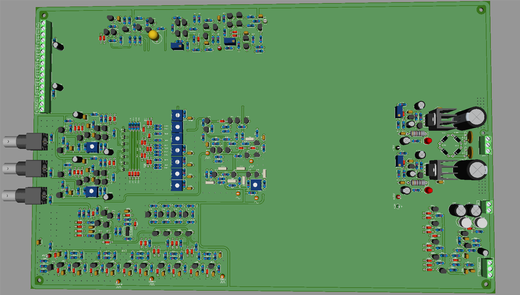
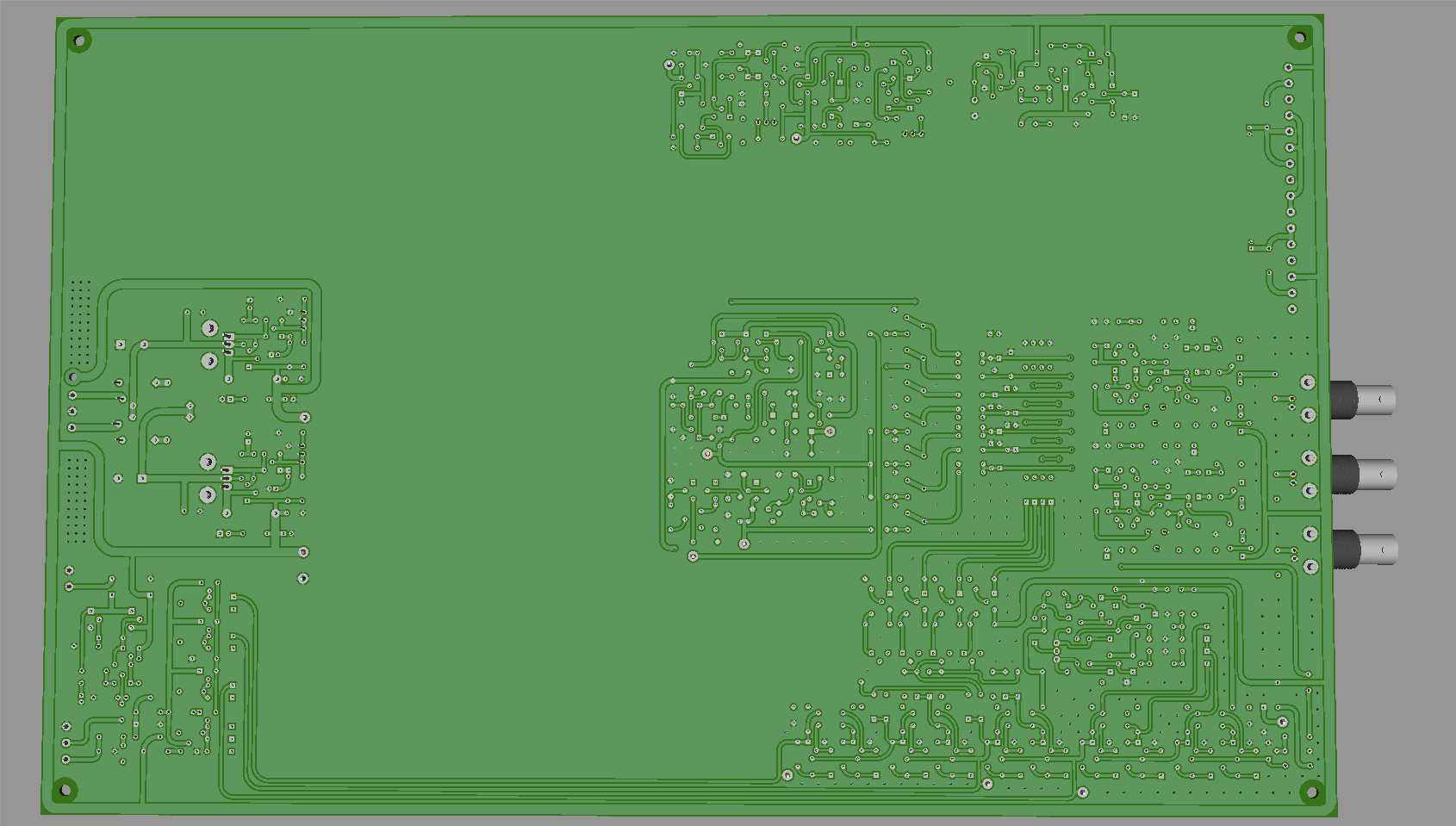
http://timb.us/Projects/Scope_Pong/Layout_20170413.pdf -
Surprised you've done that much routing before finishing placement to see how much things can be pushed together to reduce overall size (I'm assuming there's quite a bit more to fit onto that layout). Seems to be quite a lot of unused space near the BNCs that the bottom-left corner stuff could be pushed into.
As mentioned earlier,people may want to display it, so there should be room to lay the regulators and tall caps flat to allow a sensible distance to a clear cover.
You certainly also want a few more mounting hole locations for a PCB that size, and some near the BNCs for support in case the panel-mount isn't used.
-
Surprised you've done that much routing before finishing placement to see how much things can be pushed together to reduce overall size (I'm assuming there's quite a bit more to fit onto that layout). Seems to be quite a lot of unused space near the BNCs that the bottom-left corner stuff could be pushed into.
As mentioned earlier,people may want to display it, so there should be room to lay the regulators and tall caps flat to allow a sensible distance to a clear cover.
You certainly also want a few more mounting hole locations for a PCB that size, and some near the BNCs for support in case the panel-mount isn't used.
Yeah, there's quite a bit more to be done that I haven't laid out yet. Also, keep in mind some of routing between sections is just a test and not necessarily final. That PDF/image is just meant to show off the power bus more than anything. That said, I can only push things together *so* much because in certain areas I have to leave significant room to route traces between sections, for via stitching and additional mounting holes. I'm also leaving some small sections of free space to draw equivalent circuit diagrams and label the various sections on the silkscreen layer. (If that means the board has to be 400mm vs 350mm so be it; I think the end result will be worth it.)
Speaking of mounting holes, yes, I plan on adding several more mounting holes towards the middle and inner sections of the board. I'm just waiting to until I get more of the layout finished before placing them.
By the way, I *do* appreciate the feedback from everyone. I've designed 8 layer boards with 300-pin BGA packages that somehow seem *less* complex than this; having only two layers and quite a few interconnects between sections makes routing this a challenge; I'm sure there are areas where I could have laid things out more efficiently. So keep the feedback coming, it helps!
Edit: I did want to go back and push that Z-Axis block in the bottom left more towards the BNC. Now that I've got the power bus figured out I can do that. I can maybe get an additional 10-20mm out of it I think. That would also put the Multiplexer Logic/Gate Driver's more in line with the input diodes that feed the actual JFET switches, so I'd save area by shortening those traces too. -
By the way, I *do* appreciate the feedback from everyone. I've designed 8 layer boards with 300-pin BGA packages that somehow seem *less* complex than this; having only two layers and quite a few interconnects between sections makes routing this a challenge; I'm sure there are areas where I could have laid things out more efficiently. So keep the feedback coming, it helps!
Just leave enough room between all components and hit the auto router button, no problem with all these big through hole parts
-
Just leave enough room between all components and hit the auto router button, no problem with all these big through hole parts
Auto-router ->>>>>
Ok, I realize your just being cheesy...
Timb is doing perfectly. Wait till everything is done, then maybe a go-over removing jumpers if possible...
-
Just leave enough room between all components and hit the auto router button, no problem with all these big through hole parts
I actually tried that at one point, just to see how it would try to route the entire giant board in one go. I set it up, started it and wandered off to do some chores. It was only 1/4 done an hour later, so I gave up.
I might start a blank board, renew it from schematic and let it run overnight just to see what sort of spaghetti nonsense it comes up with! (When I finish the manual board I can use it to show the difference between a human and autorouter.)Auto-router ->>>>>
Ok, I realize your just being cheesy...
Timb is doing perfectly. Wait till everything is done, then maybe a go-over removing jumpers if possible...
Do you mean wire jumpers or vias? There's currently zero wire jumpers (and none planned). There are some vias, but they can't be helped. I'm trying to keep them to a minimum for you guys etching at home since I know you have to solder a piece of wire through the hole which is kind of a pain. -
What jumpers? There's currently zero wire jumpers (and none planned). There are some vias, but they can't be helped. I'm trying to keep them to a minimum for you guys etching at home since I know you have to solder a piece of wire through the hole which is kind of a pain.
Ok, it's what I meant, but it's not the end of the world...
-
What jumpers? There's currently zero wire jumpers (and none planned). There are some vias, but they can't be helped. I'm trying to keep them to a minimum for you guys etching at home since I know you have to solder a piece of wire through the hole which is kind of a pain.
Ok, it's what I meant, but it's not the end of the world...
Ah, gotcha. Yeah, I'm really trying to minimize them, but it's difficult with only two layers and all the nets running between sections.
There will also be some via stitching of the top and bottom ground planes to keep ground continuity, however, for the majority of the board they won't be an absolute necessity (as various pins are grounded and will act to bridge the two sides). So if you're etching the board at home, only a couple of the stitching vias will have to be drilled and soldered; I'll make sure the ones that are mandatory have thermals, so they can be easily identified.
Also, I'm using 0.75/1.5mm as the smallest via size, to make it easy to drill. (That's also the hole/ring size of 90% of the parts.)
Hopefully this is an acceptable compromise.
-
I put the soldering iron away this afternoon and made a start at documenting this discrete-transistor Pong MkII. This is mostly because the circuits were part scribbled on multiple sheets of paper and part in my head. By alternating between soldering and documenting the design I have less chance of getting lost.
Here are complete details of the horizontal timing and video generator board. A master LC oscillator of 500 kHz clocks a 5-bit binary ripple counter made up of cascaded toggle flip-flops.
The necessary video signals are simply decoded by (N)AND gates. Some trickery was required here however as this method of decoding a ripple counter is prone to glitches in the decoded outputs as the clock state ripples through the binary counter due to the propagation delays of the flip-flops. Glitches on the decoded outputs are not acceptable here as the video signals are being generated live as each horizontal line is being scribed on the display screen.
I solved this problem by designing the flip-flops of the ripple counter to be quite fast (using MPSH10 transistors) and conversely designing and (N)AND gates for decoding to be only adequately fast for the application, rather than excessively so, such that the decoders are too slow, by a comfortable margin, to respond to and pass through the erroneous binary states of the counter during the ripple-through of the clock.
The DTL (diode-transistor-logic) N(AND) gates are made "slow" by using comparatively-lowly BC550C transistors with a relatively weak base pull-up. The AND gates that provide the horizontal video signals for generating the scoreboard display digit segments are comprised of a BC550C NAND followed by an MPSH10 DTL inverter. The through-put propagation delay of this combo is a clean and stable ~120nS and the MPSH10 inverter provides (in addition to the required polarity inversion) a squared-up output with fast rise and fall times.
The MSB (HR16) of the horizontal ripple counter is at the line frequency (15,625 kHz) and it is used as the clock source for the vertical line counter. The horizontal video component of the paddles and the court net are approximately 600nS wide and 300nS wide respectively. As this is substantially less than the 2uS master clock period, these video signals are produced by triggering high-speed monostables.
All of the signal outputs of the horizontal timing unit are digital, bar "H_SCAN", an analogue line-scan ramp signal. H_SCAN is provided for the Ball Horizontal Movement circuit.
The board itself. I currently have a rather crappy ferrite-cored "choke" with a rather poo temperature coefficient soldered into the tank circuit of the master oscillator, as this is what immediately at hand. I'll will be sourcing a better core material to wind a better substitute.
-
Using a discrete crystal or resonator in place of the coil for your master oscillator still keeps your circuit a valid all discrete design.
It will also prevent users from accidentally destroying their TV h-sync yoke driving transistor on their TVs if the inductor driven oscillator doesn't drift the H-sync by 1/4 of a KHz. Modern digital sampling screen's ADC use tightly locked crystal PLLs, they wont be as forgiving with out of spec HSync speed compared to an all analog CRT like the Commodore 1084s monitor you are using.
The master oscillator with the current crappy inductor is already stable enough for any analogue TV or monitor and will be amply so with a better inductor. I can't immediately see how any TV could burn out its yoke due to sync frequency drift. In the absence of a video signal the raster scan oscillators are without any signal to lock onto at all and are are free to rail out or drift around within their operating frequency limits. Back in the day hobby circuits published in electronic mags for producing video displays often used a pair or 555 timers injection-locked to each other to provide the H and V sync! I have two such "vintage" articles sitting on my desk right now and I can't recall ever reading a warning to monitor your TV for smoke in addition to a stable image whilst tweaking those 555 frequency-setting trimpots!
Resonators typically have crappy tolerances and limited scope for frequency tuning and I'm not sure if they're readily available in 500 kHz. I'm going to buy one of those composite video to HDMI converters to asses how sensitive it is to the field and frame frequency stability/accuracy. Until it is proven that the basic LC oscillator is inadequate it stays. If it does prove to be inadequate or marginal I will substitute the LC oscillator with a 2MHz crystal oscillator followed by an additional pair of toggle-flip-flops to divide down to 500 kHz - 2 MHz is the nearest readily available crystal frequency, making that the only real highter-stability master oscillator option.