-
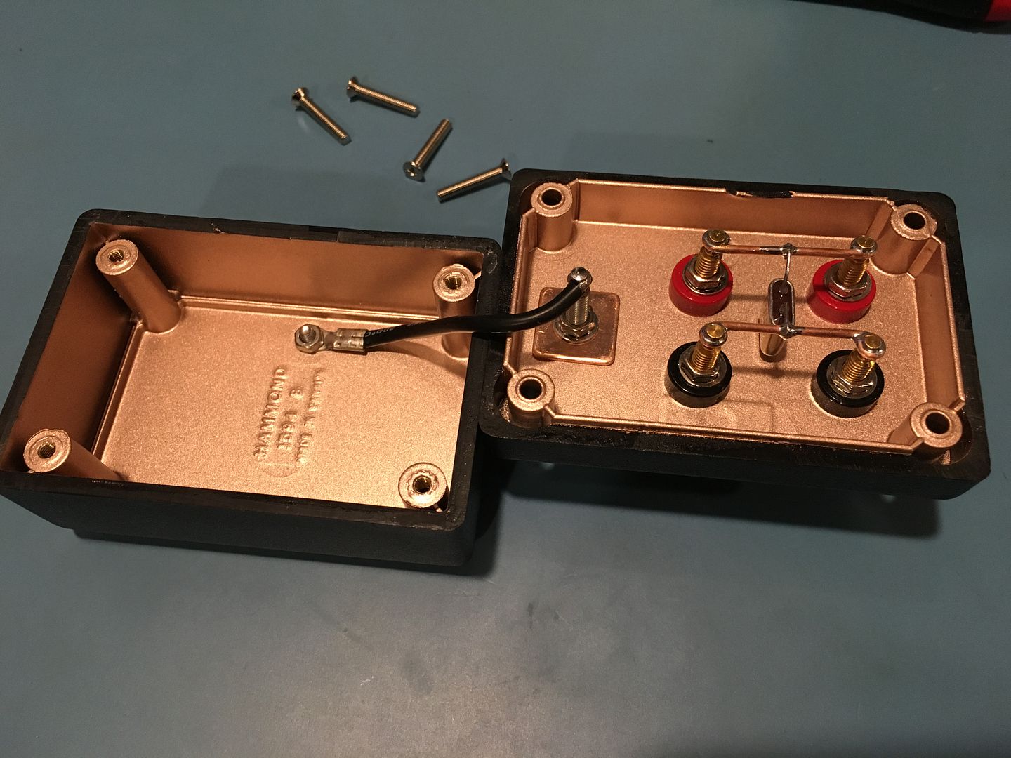
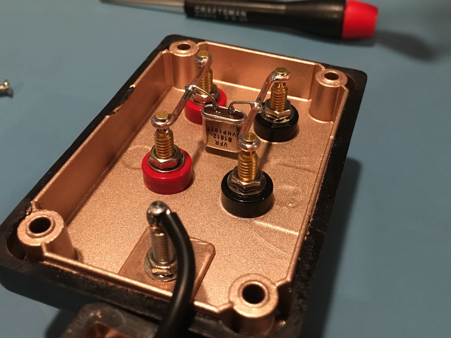
I put together a simple yet very stable, low TC home lab 10K reference just for the heck of it. The centerpiece is a Vishay VHP101 oil filled hermetically sealed 0.005% tolerance part - Y407810K0000V9L. While this is no replacement for a real secondary standard with a linear TC and predictable drift, this will make a nice cost effective reference to use around the shop with more than acceptable performance. The case is a small but heavy duty (thick wall) plastic Hammond box with a copper EMI/RFI inner coating - 1594RBBK. The thought here was to provide a slight amount of thermal stability at the same time as provide a guard path around the resistor. The posts are Pomoa 3770's for the 4W and 3760 for the guard. The only down side with the plastic case is the binding posts can be forced to apply mechanical stress on the leads to the resistor, I tried to add some strain relief on the leads. Most of the time I will be using a shielded 4w lead with spades, so binding post stress should not be a big issue.
A few days ago I did a TC sweep and comparison to a Visahy Z201 (10K, 0.005%), I was impressed with the results;
Z201: 18-28C = 0.8ppm/C. 10-40C = 0.7ppm/C.
VHP101: 18-28C = 0.05ppm/C. 10-40C = 0.05ppm/C.
Anyway, if your like me you rather look at the photos than read about it;
-
Lookin good!!


-
Quote
The only down side with the plastic case is the binding posts can be forced to apply mechanical stress on the leads to the resistor, I tried to add some strain relief on the leads.
Maybe an inner steel plate with flattened holes, like the molds from the Pomona plastic bushings?
-
Quote
The only down side with the plastic case is the binding posts can be forced to apply mechanical stress on the leads to the resistor, I tried to add some strain relief on the leads.
Maybe an inner steel plate with flattened holes, like the molds from the Pomona plastic bushings?
I actually thought about doing just that, but after it was assembled. -
That fancy copper lined case probably cost more than the die-cast aluminum ones I use for everything.
Nice project. Thanks for showing pictures. One day I'll be able to make charts like that but not yet.
Respectfully,
George Dowell
-
$11 from Mouser for the Hammond 1594RBBK box.
$61 from Texas Components for the Vishay Y407810K0000V9L resistor.
$10 each for the 3770 binding posts and $5 for the 3760. -
@kj7e
nice build
how about a precision 10K thermister (kelvin sensed) also?
btw. what is your measurement setup?
best regards.
-zia
-
A temp sensor here wont yield much benefit with this build. There will likely be more annual shelf life drift than the TC within the normal room temp range (23C +or- 5) and the TC for the VHP101 is not very linear, so computing projected TC error is not very accurate here.
I use a Keiithley DMM7510 and Keysight 34465A. My TEC box is a bit crude at the moment, but I have a new project on my bench I started on today to address this
-
Nice and compact built!
Your VHP101 seems to be right in the middle between the binding posts.
How did you decide which side to use for sense and which side is force?
I have always placed the resistor as close as possible to the force terminals.
May be it is not needed.
May be even better for mechanical stress to keep the resistor in the middle?
I place the resistor in the center as well and always use tick copper conductor. -
I just order a 10K 0 PPM resistor:
Resistance 10 kOhms
Tolerance ±0.005%
Power (Watts) 0.3W
Composition Metal Foil
Features Moisture Resistant, Non-Inductive
Temperature Coefficient 0.0ppm/°C
Operating Temperature -55°C ~ 125°C
Package / Case Radial
Is 0 PPM really possible?
-
HV, in theory it would be best to place the resistor as close to the sense binding posts as possible. With a 4W Kelvin setup, the Force side should burden all lead resistance and the Sense side should be as close to the DUT as possible with minimal lead resistance. After reading the Standard Resistor teardown thread about 20 times, I decided it must not make much difference in the real world and to follow the examples from Fluke and others;
https://www.eevblog.com/forum/metrology/teardown-standard-resistors/
It really does not matter which side is force or sense in my case. So again I followed what seams to be the industry standard and put the Force on the Left.
eurofox, no such thing as a 0ppm TC. Also, the best TC specs from Visahy are typical values, not factory tested and guaranteed. You will need to do your own testing to really know what you have. I think I got lucky with my sample. -
Looks nicely made, possible improovements could be to add a heatsink and a temp sensor
see example from Dr. Frank
https://www.eevblog.com/forum/metrology/t-c-measurements-on-precision-resistors/msg464413/#msg464413 -
Looks nicely made, possible improovements could be to add a heatsink and a temp sensor
see example from Dr. Frank
https://www.eevblog.com/forum/metrology/t-c-measurements-on-precision-resistors/msg464413/#msg464413
Hi quarks,
I think that device of Dr. Frank was for TC testing, so high thermal conductivity and low gradient was important. This box is just a reference and not for TC testing use. The enclosure design goals for this project was, remove air drafts, static field and some EMI/RFI protection, and add some additional thermal stability from outside ambient influences (such as the A/C coming on or the shop door opening with a cool air draft). This is why I chose the copper lined plastic enclosure over aluminum. Also, this gives me a true guard path around the resistor. It seems to work well, its not sensitive at all to handling the enclosure while measuring, but if you put your hands near the unshielded test leads you will see the static charge influence.
For TC testing, I have a new thermal box I'm building on my bench now. That WILL have a 4 wire PT100 and other sensors, its a heavy thick wall aluminum box with uniform heating elements, but this will be saved for a separate thread. -
"For TC testing, I have a new thermal box I'm building on my bench now. That WILL have a 4 wire PT100 and other sensors, its a heavy thick wall aluminum box with uniform heating elements, but this will be saved for a separate thread. "
I for one can't wait for that report.
George Dowell
-
I made a copy using a Vishay 0TC part - much appreciate the idea! Mine's in a metal box with a thermistor. I used the 0.0% TC unit from Digi-Key.
-
I made a copy using a Vishay 0TC part - much appreciate the idea! Mine's in a metal box with a thermistor. I used the 0.0% TC unit from Digi-Key.
Posting this now requires you to post up a photo .
.
-
Hi quarks,
I think that device of Dr. Frank was for TC testing, so high thermal conductivity and low gradient was important. This box is just a reference and not for TC testing use. The enclosure design goals for this project was, remove air drafts, static field and some EMI/RFI protection, and add some additional thermal stability from outside ambient influences (such as the A/C coming on or the shop door opening with a cool air draft). This is why I chose the copper lined plastic enclosure over aluminum. Also, this gives me a true guard path around the resistor. It seems to work well, its not sensitive at all to handling the enclosure while measuring, but if you put your hands near the unshielded test leads you will see the static charge influence.
For TC testing, I have a new thermal box I'm building on my bench now. That WILL have a 4 wire PT100 and other sensors, its a heavy thick wall aluminum box with uniform heating elements, but this will be saved for a separate thread.
Well , my design is indeed intended as a secondary resistor standard, not only for T.C. testing, and temperature balancing and measurement is strictly required for any reference resistors, see esi SR104 box.
Your box has several bugs:
- Too thick copper wires .. these are heat sinks and create temperature imbalance via the measuring cables
Due to 4 wire Kelvin connection, location of soldering does not play a role.
You also should have avoided heating the VHP resistor during soldering, so these thick copper wires are no good.
- missing aluminium or copper block, assembled to case - your setup creates further temperature imbalances between case and resistance element.
The oil filling would also short temperature gradients
- missing thermometer to precisely determine T.C. in first place, and in use would give the opportunity to precisely determine its R(T), again see esi SR104.
The oil filled hermetically sealed Vishay resistors are extremely stable over time, the specification is < 2ppm / 6 years for shelf life, which seems to be correct from my long term monitoring of five VHP202Z.
So it's really a pity that you regard this resistor as being shabby. -
All good points Dr. Frank. Ill keep these in mind for v2.
-
Hi quarks,
I think that device of Dr. Frank was for TC testing, so high thermal conductivity and low gradient was important. This box is just a reference and not for TC testing use. The enclosure design goals for this project was, remove air drafts, static field and some EMI/RFI protection, and add some additional thermal stability from outside ambient influences (such as the A/C coming on or the shop door opening with a cool air draft). This is why I chose the copper lined plastic enclosure over aluminum. Also, this gives me a true guard path around the resistor. It seems to work well, its not sensitive at all to handling the enclosure while measuring, but if you put your hands near the unshielded test leads you will see the static charge influence.
For TC testing, I have a new thermal box I'm building on my bench now. That WILL have a 4 wire PT100 and other sensors, its a heavy thick wall aluminum box with uniform heating elements, but this will be saved for a separate thread.
Well , my design is indeed intended as a secondary resistor standard, not only for T.C. testing, and temperature balancing and measurement is strictly required for any reference resistors, see esi SR104 box.
Your box has several bugs:
- Too thick copper wires .. these are heat sinks and create temperature imbalance via the measuring cables
Due to 4 wire Kelvin connection, location of soldering does not play a role.
You also should have avoided heating the VHP resistor during soldering, so these thick copper wires are no good.
- missing aluminium or copper block, assembled to case - your setup creates further temperature imbalances between case and resistance element.
The oil filling would also short temperature gradients
- missing thermometer to precisely determine T.C. in first place, and in use would give the opportunity to precisely determine its R(T), again see esi SR104.
The oil filled hermetically sealed Vishay resistors are extremely stable over time, the specification is < 2ppm / 6 years for shelf life, which seems to be correct from my long term monitoring of five VHP202Z.
So it's really a pity that you regard this resistor as being shabby.
I build one using the same resistor but mount it in an aluminium box, use wires with similar diameter of the resistor wires, use the full length of the resistor wires and put clip on the wires to bypass the heat during soldering. -
Sorry for stupid question:
Can I buy similar resistors on Ebay?
Can I use some wirewound resistors from old resistance decade? -
Sorry for stupid question:
Can I buy similar resistors on Ebay?
Can I use some wirewound resistors from old resistance decade?
You can buy it from Mouser, they ship free of charge above 50€ to Europe in just 2-3 days and since this resistor cost almost 50€ you just need to ad some small parts.
With respect to old wire wound resistor you can use it but will not be the same result
-
Sorry to reply at such an ancient post, but was thinking about using a low tempco trimmer to trim a slightly lower 10k resistor to tune it to a perfect 10k.
I wanted to use a standard 71-Z201T10K000VB Vishay resistor with a 0.2ppm, choosing one that measures around 999,995 or so and add something like this: Y005610R0000K0L 10R Trimmer so that I can reach a perfect 10k... the tempco of that trrimmer is 15ppm but on 10 Ohm, and it's really cheap compared to the 10ppm part which is like 60 Euro each. This one goes for around 18 Euro.
And obviously ask the help of some merciful soul here so that it can be tuned to that value on a real voltmeter, 7.5 or even 8.5 digit machine - without spending a fortune.
Nicest machine i own is a 34410A, plus another classic 34401A.
Reasoning behind this and not choosing a single fixed resistor of the correct value, maybe with like 1PPM, to trim the Foil resistor: I dont want to make it hard for whoever is doing me this favour to do a very tedious operation of soldering the tuning resistor(s) or purchasing lots of different and expensive parts to do this. All the friend would have to do is leave it on a bench for a day or so and then tune it with the trimmer noting the temperature at which the calibration was done.
what do you think? -
Why do you need exact 10K? A known (small) difference works as well in most cases.
-
Sorry to reply at such an ancient post, but was thinking about using a low tempco trimmer to trim a slightly lower 10k resistor to tune it to a perfect 10k.
trimmers are usually bad idea for anything super accurate. Secondly it is usually better to add large value resistor+trimpot in parallel to trimmed resistor to make the contact resistance variation smaller.
I wanted to use a standard 71-Z201T10K000VB Vishay resistor with a 0.2ppm, choosing one that measures around 999,995 or so and add something like this: Y005610R0000K0L 10R Trimmer so that I can reach a perfect 10k... the tempco of that trrimmer is 15ppm but on 10 Ohm, and it's really cheap compared to the 10ppm part which is like 60 Euro each. This one goes for around 18 Euro.
And obviously ask the help of some merciful soul here so that it can be tuned to that value on a real voltmeter, 7.5 or even 8.5 digit machine - without spending a fortune.
Nicest machine i own is a 34410A, plus another classic 34401A.
Reasoning behind this and not choosing a single fixed resistor of the correct value, maybe with like 1PPM, to trim the Foil resistor: I dont want to make it hard for whoever is doing me this favour to do a very tedious operation of soldering the tuning resistor(s) or purchasing lots of different and expensive parts to do this. All the friend would have to do is leave it on a bench for a day or so and then tune it with the trimmer noting the temperature at which the calibration was done.
what do you think?
Sneaky bastards at Vishay specify C.R.V 3 to 10 ohms without telling what it means (contact resistance variation)
10 ohm random contact resistance would make your project futile if you used 10 ohm trimpot in series. Better way would be something like 100M fixed resistor and 10k trimmer in parallei with your precision resistor.


