Author Topic: DMTD board  (Read 85433 times)

0 Members and 1 Guest are viewing this topic.

Online 5065AGuruTopic starter

  • Frequent Contributor
  • **
  • Posts: 355
  • Country: us
Re: DMTD board
« Reply #325 on: December 20, 2020, 02:48:50 am »
Taka,

I usually power them for at least 24 hours, do a first plot, and then comparison plots each day.

After a few days you will be able to select out the more stable performers.

Cheers,

Corby
 

Offline notfaded1

  • Frequent Contributor
  • **
  • Posts: 559
  • Country: us
Re: DMTD board
« Reply #326 on: December 22, 2020, 08:39:58 pm »
What PCB's you use for the 10811's taka?

Regards,

Bill
.ılılı..ılılı.
notfaded1
 

Offline tkamiya

  • Super Contributor
  • ***
  • Posts: 2178
  • Country: us
Re: DMTD board
« Reply #327 on: December 22, 2020, 09:27:08 pm »
I made my own.  The circuit is combination of what HP does in their products and what's in the data sheet.  Feed 24V and the rest is regulated down from it.  I'll be happy to provide Gerbers for it, if you'd like.
 
The following users thanked this post: notfaded1

Offline notfaded1

  • Frequent Contributor
  • **
  • Posts: 559
  • Country: us
Re: DMTD board
« Reply #328 on: December 23, 2020, 11:27:27 am »
New power supplies I'm going to try.  It should be easy to experiment with different supply voltages.  It's interesting the original design had higher negative 5VDC you said -5.2VDC vs. the +5VDC.  Some progress.

Bill
.ılılı..ılılı.
notfaded1
 

Offline tkamiya

  • Super Contributor
  • ***
  • Posts: 2178
  • Country: us
Re: DMTD board
« Reply #329 on: December 23, 2020, 01:16:04 pm »
Since this project, I have been paying attention on supply voltages.  I found several HP frequency counters having the same scheme of +5V and -5.2V, so this seems to be a common practice.  I'm thinking it may have something to do with noise with OPamps.  I wonder what happens to dynamic range and NULL value?  Would the null value be a mid point which is 0.1V?  Or would difference in supply voltage appear as different max values/swings?  (having negative swing larger than voltage) but null is still at 0V? 
 

Offline tkamiya

  • Super Contributor
  • ***
  • Posts: 2178
  • Country: us
Re: DMTD board
« Reply #330 on: December 23, 2020, 10:35:57 pm »
Here's the ZIP for 11801 interface board design.

Please see SEEME_FIX.jpg for jumpers that are required.  These files were created using KiCad.  Gerbers ready for upload is in 10811interfaceV1.4/11801v1_4gerbers/HP11801interfaceV1_4gerbers.zip.  (yes, I misspelled the name)  I used PCBWay as a fabricator.  I've attached a comment to my order stating "Hole overlaps around a connector is intended.  Expect elongated through holes."  Expect the cost to be around $5 for 10 PCB + fees and shipping.

Please note, spacing for capacitors are tight both vertically and horizontally.  I chose smallest 35V type I can get from Digikey.  Or, you could possibly install them on the other side if clearance is an issue.  This board contains circuits in HP's own implementations of 10811, and what's in datasheet.  Please see circuit design for detail.  Goal of this board is to give 24V and create all voltages necessary for 10811 to operate.  EFC is provided on PLUS SIDE ONLY.  Output is not buffered but is DC isolated.  Please note, 30 pin connectors come in two different spacing between rows.  Both 2.54mm and 3.96mm versions work (thus the elongated holes)

Please use this at your own risk.  I am successfully using it (after jumpers) but I do not claim it to be error free.
« Last Edit: December 23, 2020, 10:48:31 pm by tkamiya »
 
The following users thanked this post: materialsguy, notfaded1

Offline tkamiya

  • Super Contributor
  • ***
  • Posts: 2178
  • Country: us
Re: DMTD board
« Reply #331 on: December 27, 2020, 12:03:40 am »
I did my first long run as long as a bunch of short ones.

Please ignore the label.  There is no MV89a involved.  That is a naming mistake.
Reference is 10MHz from HP105B
DUT is HP11801-6011
Local (difference) is Oscilloquarz 8663 which is set to 1Hz over 10MHz.
Data was dumped to ascii file and imported into TimeLab.  Please see the import/acquisition screen.

I did few short runs as you can see.  They pretty much agree, so at least the result is consistent.  An odd thing though, this is not the kind of graph I expected.  First, it is starting somewhere around 6x10E-10.  It will quickly go down to  6x10E-12, then starts to go up.  My understanding was that OCXO are stable for short term, up to 100s or less and it will deteriorate.  The graph shows differently.  As suggested by someone earlier, I also did time deviation.  It pretty much agrees with my assumption... except... (see next)

Another thing is, 6x10E-10 as initial value is not what I expected by order of magnitude.  I expected 10 times better. 

I did multiple pieces (not shown in this post).  They were either almost identical to this, or two orders of magnitudes worse.  I'd imagine those pieces may not even be functioning correctly. 

Sorry folks - I don't remember how to screen dump.  But I hope you'll get the gist.  I'm soliciting any hint, suggestions, etc, etc, etc. 
 

Online KE5FX

  • Super Contributor
  • ***
  • Posts: 1903
  • Country: us
    • KE5FX.COM
Re: DMTD board
« Reply #332 on: December 27, 2020, 12:14:49 am »
Hint: don't even look at ADEV until you've looked over the frequency and/or phase-difference plots to evaluate the quality of your data.

(Also, ctrl-c will copy the screen to your clipboard, it's also near the top of the File menu.)
 

Offline tkamiya

  • Super Contributor
  • ***
  • Posts: 2178
  • Country: us
Re: DMTD board
« Reply #333 on: December 27, 2020, 12:27:09 am »
But what am I looking for? 

This is what it looks like now.  (please don't mind the color change....  blue = red same data)
 

Online KE5FX

  • Super Contributor
  • ***
  • Posts: 1903
  • Country: us
    • KE5FX.COM
Re: DMTD board
« Reply #334 on: December 27, 2020, 12:40:19 am »
You can tell by looking at the 'p' and/or 'f' traces if the drift or other instability was constant over your test run, or if it came and went for some reason.  For instance, occasional outliers -- anything from excessive popcorn noise to bumping the table -- can explain excessive instability at longer-term taus.  These can be removed with F4 (see the manual) if you're sure you can account for them.

Low-level spikes may suggest EMI that can affect short-term ADEV.  Low-level noise may be OK, if it occurs at the level expected due to counter quantization noise or trigger jitter, but watch out for low-level tones.  These appear as ripple on the ADEV plot and regular cyclic artifacts on the frequency-difference plot, and could suggest external interference or crosstalk from a nearby source.

Note how John Ackermann uses phase- and frequency-difference traces to study the behavior of the HP 5370B.

To look for the lower-level artifacts, hit 'r' to take the linear trend out, so you can see the residual.  The 'r', 'z', and 'y' hotkeys will end up being baked permanently into your muscle memory, or at least they should. :)
 

Offline tkamiya

  • Super Contributor
  • ***
  • Posts: 2178
  • Country: us
Re: DMTD board
« Reply #335 on: December 27, 2020, 12:53:41 am »
John,

Nothing is jumping out at me.  I knew those waviness on Adev curb exists on everyone of my graphs.  With 60Hz and 10MHz everywhere near the testing setup, I can imagine interference is common.  I can set it up in middle of my 3/4 acre yard if I have to.  I don't see any peculiar peaks.  I don't see any abrupt changes.  I've been at this for almost a year now. 
 

Online 5065AGuruTopic starter

  • Frequent Contributor
  • **
  • Posts: 355
  • Country: us
Re: DMTD board
« Reply #336 on: December 27, 2020, 11:44:25 pm »
Taka,

Can you share the raw data file for the long (>1day) run.

Also what counter were you using?

I'd like to see what's happening.

Cheers,

Corby
« Last Edit: December 27, 2020, 11:50:57 pm by 5065AGuru »
 

Offline tkamiya

  • Super Contributor
  • ***
  • Posts: 2178
  • Country: us
Re: DMTD board
« Reply #337 on: December 27, 2020, 11:51:46 pm »
Here it is....

I've communicated with John and he gave me wonderful answers.  I'll just see if I can solve the problems he mentioned.
 

Online 5065AGuruTopic starter

  • Frequent Contributor
  • **
  • Posts: 355
  • Country: us
Re: DMTD board
« Reply #338 on: December 28, 2020, 12:46:15 am »
Taka,

It appears that your DUT and REF are WAY TO FAR apart in frequency. :wtf:

Measure the REF on a good counter and then adjust the DUT on the same counter to be within .001HZ of the REF (1X10⁻¹⁰th)

Then look at the counts on your DMTD counter. You should see the counts either going up or coming down.

Adjust the DUT or REF carefully to make the counts increment as slowly as possible.

Trying to do this with the oscillators adjustment capacitor is not going to work. (With a lot of messing around you might get it to work just to try)
I see your REF is a 105B so the fine adj pot will work with it.

Added coarse and fine EFC pots are the way to go.

Now take data say for 15 minutes and see what you get. :-+

Your phase plot should look smooth with no wraps for such a short plot.

Cheers,

Corby


Offline tkamiya

  • Super Contributor
  • ***
  • Posts: 2178
  • Country: us
Re: DMTD board
« Reply #339 on: December 28, 2020, 03:28:45 am »
Corby,

I've adjusted DUT to match reference within 0.0xHz.  Here's the results.  Red line is the new trace.  Blue trace is the old.  It's better but in Phase difference and Frequency difference plot, I'm still seeing something funny.  My lab is not a good environment.  10MHz signal everywhere.  I'm going to isolate the system to middle of my living room and see if I can eliminate possible interference.  This will take few days.

I'm also going to have to modify my DMTD to bring out another output so that I can hook up a scope.  Frequency counter won't cut it as its reference is GPDSO.  I'm sure (hope) my OCXO is more stable than that in short term.
« Last Edit: December 28, 2020, 03:37:17 am by tkamiya »
 

Online 5065AGuruTopic starter

  • Frequent Contributor
  • **
  • Posts: 355
  • Country: us
Re: DMTD board
« Reply #340 on: December 28, 2020, 04:27:55 am »
Taka, That does look a bit better but I'd need the raw data again so I can see what's going on.

Cheers,

Corby
 

Offline tkamiya

  • Super Contributor
  • ***
  • Posts: 2178
  • Country: us
Re: DMTD board
« Reply #341 on: December 28, 2020, 05:33:42 am »
Here it is.
 

Online 5065AGuruTopic starter

  • Frequent Contributor
  • **
  • Posts: 355
  • Country: us
Re: DMTD board
« Reply #342 on: December 28, 2020, 06:53:38 am »
Taka,

Well you are about 6X10⁻¹⁰ offset between the DUT and REF so you are wrapping every 165 Sec or so.

You can't do an Allan Deviation on the whole file because of the wraps!

You can remove all but one cycle and run a plot on that or remove all the wraps.

You need to get them close enough so that they don't wrap so quickly.

Look at the DMTD tutorial post, in the example shown they did not wrap for over 2000 Sec.

Like I said adjust to make the count almost stop changing prior to taking the data.

Here is a phase plot of your file.

What counter are you using?

Cheers,

Corby

P.S. Going offline for tonight.


Online KE5FX

  • Super Contributor
  • ***
  • Posts: 1903
  • Country: us
    • KE5FX.COM
Re: DMTD board
« Reply #343 on: December 28, 2020, 08:19:48 am »
Here's how the data from corby1.txt looks in TimeLab:


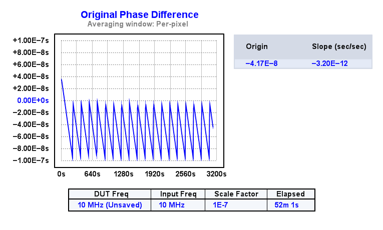
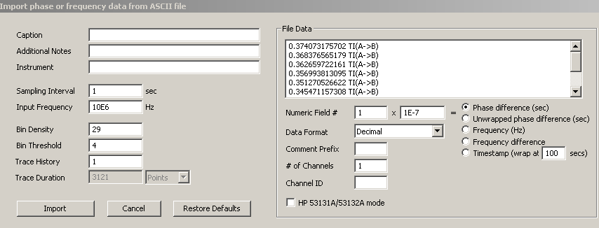
This is the original wrapped phase data ('w') view of corby1.txt, which I imported as follows:


With those import settings, TimeLab will unwrap the phase automatically.  Pressing 'p' shows this view of the data:


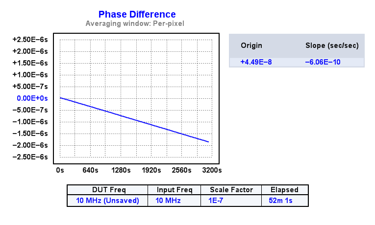
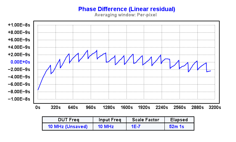
As you (Corby) note, this is a frequency error of 6E-10, which should be OK.  There is normally no need to avoid phase wrap, as long as it happens slowly enough to obey the usual Nyquist limit.  (If you want to eliminate all relative drift between the reference and DUT, you should use a tight PLL rather than a DMTD!)  It's necessary to look at the residual ('r') to see the fine details:


Or differentiate it, by looking at the effect in the frequency ('f') difference view:


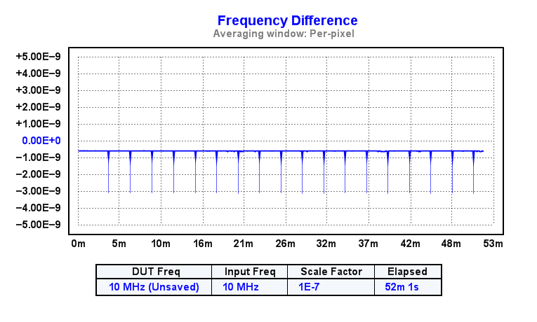
The question I have is, where is the 2ns sawtooth coming from?  The 2ns resolution of the counter should be swamped by a factor of 1E7, taking it out of the picture entirely, but for some reason we still see this 2 ns glitch every couple of minutes when the phase wrap occurs.  If I zoom in on each of those spikes in the frequency-difference view and remove it with F4, I get a more believable result:


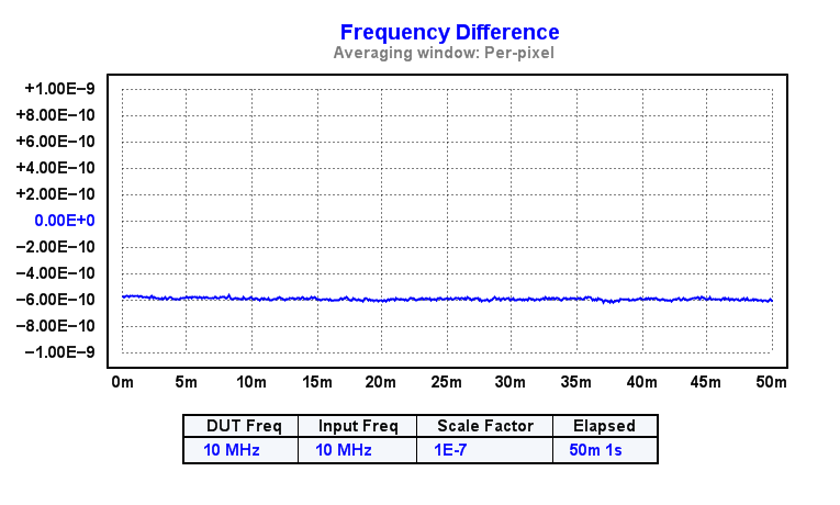
Hitting 'z' to position the trace for viewing at a zero baseline:


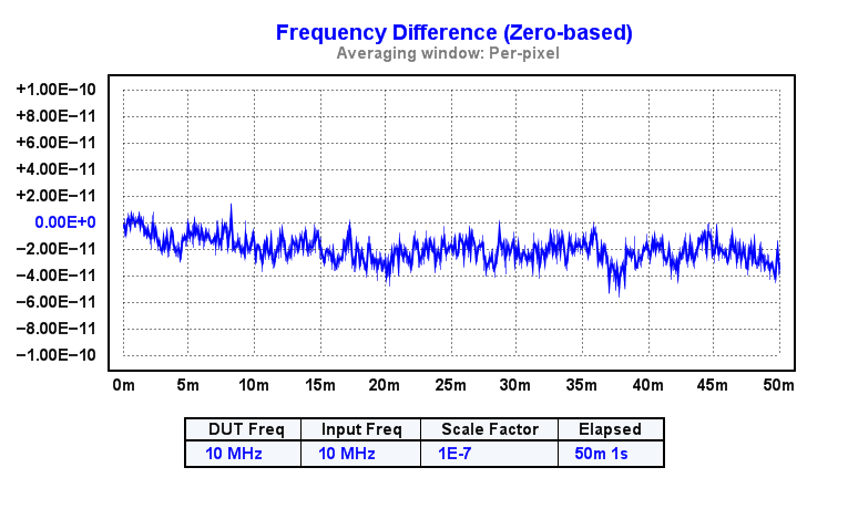
The phase drift now looks like this, compared to the original data:


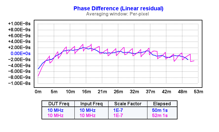
Again, a perfectly-reasonable display of two decent 10 MHz oscillators being compared to each other.  ADEV now looks like this:


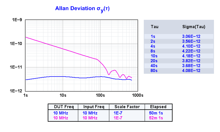
Once again, very believable.  But what's up with those spikes at the wrap point?  They shouldn't be there, unless the counter has a bug or calibration issue, or I'm overlooking something about how the DMTD works. 
 

Offline tkamiya

  • Super Contributor
  • ***
  • Posts: 2178
  • Country: us
Re: DMTD board
« Reply #344 on: December 28, 2020, 08:51:59 am »
My counter is TAPR TICC with all settings at default. 

I'll use my scope to set frequency of DUT and REF exactly and see what happens.  I thought TimeLab can take care of wrapping issue, so I CAN do the Adev....  no?  I do have number of different counters so I can try that, too.  TICC is just easier, so I was staying consistent with it.

Something I forgot to say yesterday.
My difference oscillator is a simple oscilloquartz 8663 set at 10MHz + 1 Hz.  Power supply for this is a switching regulator - the one someone talked about on TimeNuts list.  This is supposed to be a low noise type for pre-amps.  I never bothered to measure it.  So it could be dirty.  It'd be easy to use a linear supply.

By the way....  TICC and CorbyDMTD, and all the oscillators EXCEPT DUT are all in metal case.  Internal wirings are semi-flexible coax (the type with no outside and tin soaked braid is exposed.  Connectors are either N or SMA.  (I don't trust BNC)  Coax is all good to great quality.  TimesMicrowave LMR 200 and some uber expensive ones I got second hand.  I've tried to limit signal leaks.

Thank you very much for looking at my data.  I owe you some beer.
 

Offline tkamiya

  • Super Contributor
  • ***
  • Posts: 2178
  • Country: us
Re: DMTD board
« Reply #345 on: December 28, 2020, 08:57:16 am »
About the Adev graph above, is it reasonable that it is staying that low beyond 100 seconds?  I thought it should start rising at around 100s.

John, how are you arriving at 2nS figure?  Will you share how you are reading the saw tooth graph?
 

Online KE5FX

  • Super Contributor
  • ***
  • Posts: 1903
  • Country: us
    • KE5FX.COM
Re: DMTD board
« Reply #346 on: December 28, 2020, 09:45:14 am »
John, how are you arriving at 2nS figure?  Will you share how you are reading the saw tooth graph?

Just refer to the Y axis labels in the phase-difference plot above.  They are in seconds.

I thought you were using an HP 5334A for some reason, which has a 2-ns single shot resolution, but I believe the TICC is more like 80 ps.  So the ~2ns height of the sawtooth-shaped phase glitch doesn't make much sense either way.  Before the 1E-7 scale factor is applied, this is more like a 20-millisecond error that is showing up every time the counter wraps.  Some sort of dead time effect, perhaps, that occurs whenever the counter thinks its STOP signal is arriving before the START signal.

Note that your data is quite clean-looking once the wrap glitches are removed.  You can stop worrying about the test environment for now, and focus on getting the counter to report valid results in the presence of phase wraps.  Or, as Corby suggests, move the oscillators so close together that they don't wrap at all during your test period.  That obviously puts massive limitations on what the system can do, so it would be better to get the setup working properly with wrapping.

About the Adev graph above, is it reasonable that it is staying that low beyond 100 seconds?  I thought it should start rising at around 100s.

Yes, a good 10811 will easily stay below 1E-11 at t=1000 seconds or more.  E.g.:


Offline thinkfat

  • Supporter
  • ****
  • Posts: 2152
  • Country: de
  • This is just a hobby I spend too much time on.
    • Matthias' Hackerstübchen
Re: DMTD board
« Reply #347 on: December 28, 2020, 10:21:34 am »
The TICC is a timestamping counter. There should not be any problem around phase wraps since it just calculates the difference between two consecutive timestamps. It should not matter whether channel A comes before B or vice versa as each of the channels delivers timestamps independently.

@tkamiya can you record a series in timestamping mode, or even better in debug mode that contains at least one wrap? Don't bother importing in TimeLab, just post the raw capture data. This will allow me to have a look at the individual channels and to see if there's any funny business going with the individual timestamps.
« Last Edit: December 28, 2020, 10:34:32 am by thinkfat »
Everybody likes gadgets. Until they try to make them.
 

Offline tkamiya

  • Super Contributor
  • ***
  • Posts: 2178
  • Country: us
Re: DMTD board
« Reply #348 on: December 28, 2020, 01:01:26 pm »
John,

When Corby suggested, I measured DUT frequency.  It was almost exactly .1Hz off
 

Offline tkamiya

  • Super Contributor
  • ***
  • Posts: 2178
  • Country: us
Re: DMTD board
« Reply #349 on: December 28, 2020, 08:53:01 pm »
I'm so glad I've included EFC in my 11801 board. 

I am going to try using different counters to see if the wrap-spike is caused by TICC.  I kind of doubt it but I have multiple 53132A, HP5335A, and HP5370B.  Trying one of each should tell me if I'm on the right track.  I've been wanting to separate time-nuts stuff from general lab.  I may just to it sooner than later.  Lab temperature changes too much.


Share me

Digg  Facebook  SlashDot  Delicious  Technorati  Twitter  Google  Yahoo
Smf