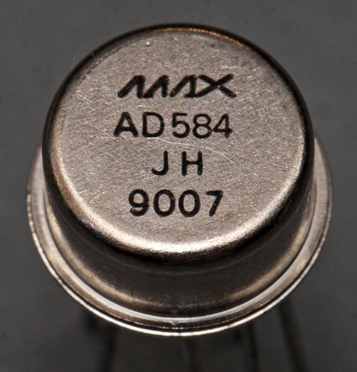
As the name implies, the AD584 reference voltage source was originally developed by Analog Devices. Maxim had its own variant on offer, which can be seen here. The index J is the worst of three bins. The best bin L offers an accuracy of +/-2,5mV (on the 2,5V rail). The temperature drift is typically given as 3ppm/°C. In addition, there is a long-term drift of 25ppm/1000h. The noise voltage is 50µVpp (0,1-10Hz). The output delivers up to 10mA. A strobe input can be used to deactivate the AD584, which reduces the current consumption from 750µA to 100µA.
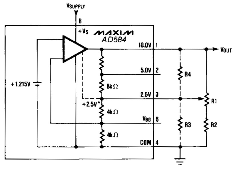
The AD584 offers four outputs: 10V, 5V, 2,5V and the bandgap voltage, which usually is 1,215V. The datasheet shows how to adjust the reference voltage to other values with additional resistors.
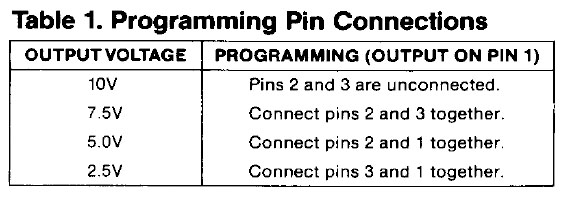
Depending on which output voltage you want to use, you can bridge different pins and thus adjust the internal voltage divider. In such a connection, the respective output offers the specified load capacity. If you use an external buffer, you can work without bridges and also access several of the output voltages.
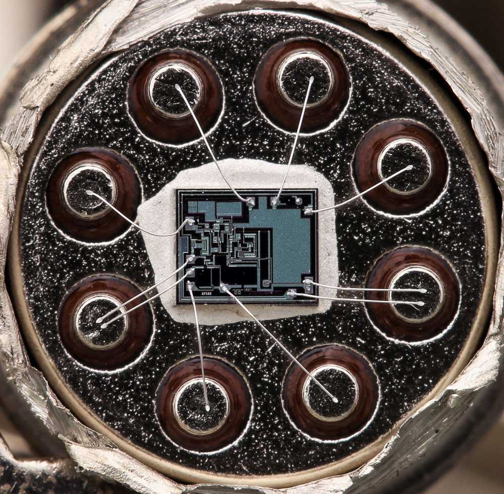
In the housing it can be seen that both the 10V reference potential and the reference potential are connected with two bondwires. Here, the connection has not simply been reinforced. On the die, the bondwires each contact different potentials.
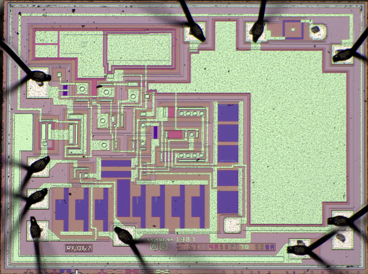
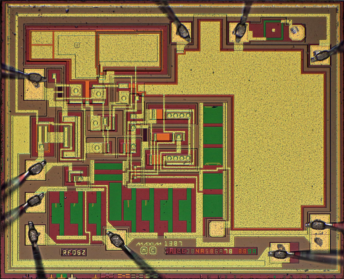
The dimensions of the die are 2,2mm x 1,8mm.

The design is obviously from Maxim and dates back to 1987.
Nine masks are depicted on the lower edge of the die. Many can be assigned to their function. 1A depicts the low-lying collector feed line. 2E creates the isolated areas. 4A represents a strong n-doping. Since the metal layer is preceded by mask 5B, it seems likely that 4A generates so-called sinkers, the connection between the low-lying n-dotations and the surface. 5B then generates the emitter regions. 6A creates openings in the silicon oxide through which the metal layer contacts the active elements. 7B then structures the metal layer. 9A obviously serves to define the shape of the adjustable resistors. 8B could be the mask that opens the passivation layer in the bond areas.
Some masks have been revised once. The mask for the isolated wells (2E), on the other hand, has been revised four times.
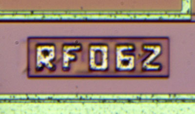
RF06Z seems to be the internal designation of the AD584. One can guess that at least a similar string is shown in the lower layers.
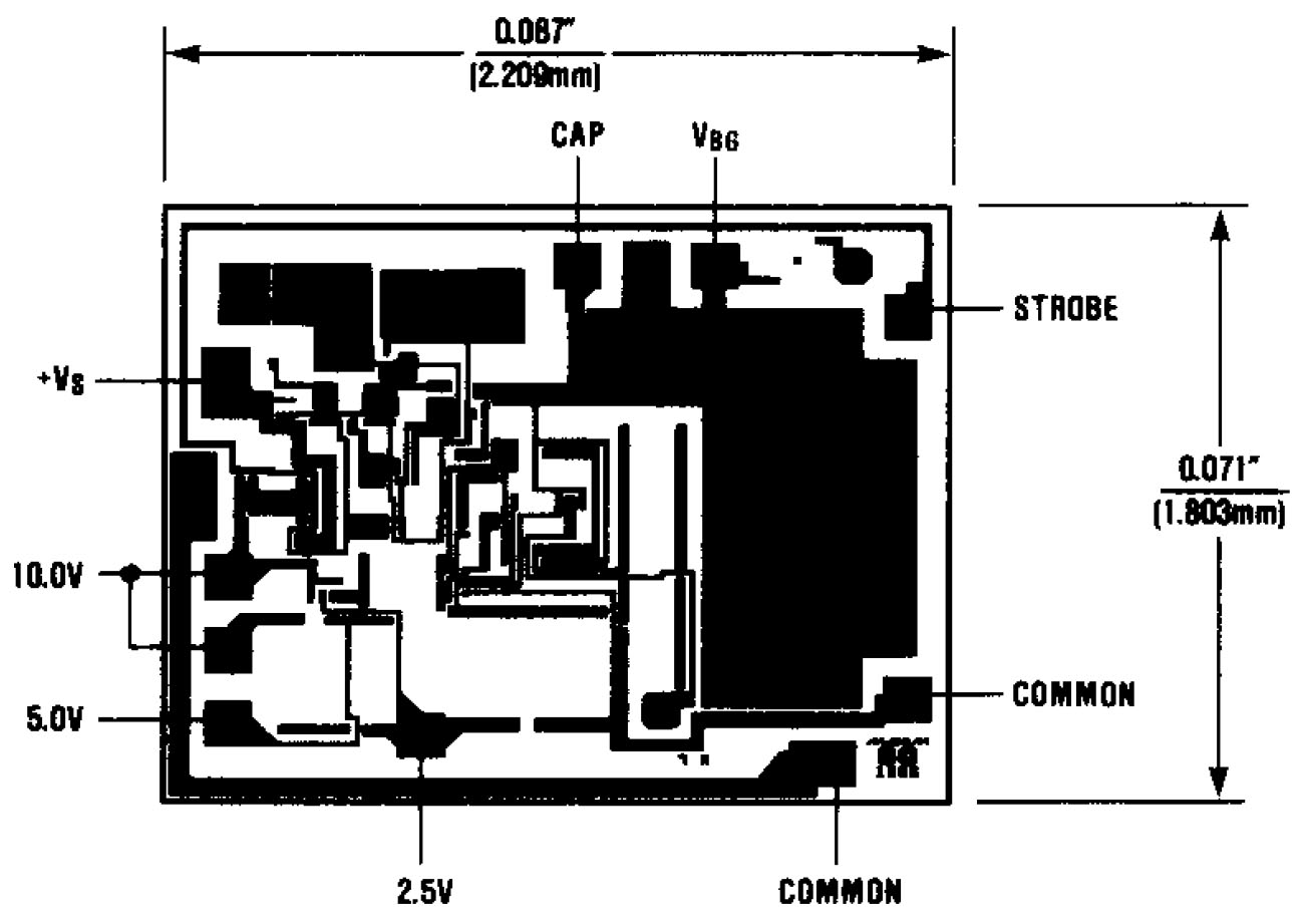
The Maxim datasheet for the AD584 contains an illustration of the metal layer that matches the present die very well. The only noticeable difference is in the bottom right corner, where the bondpad for the reference potential has been extended on the present die. The Maxim logo with the copyright had to be moved to the left accordingly.
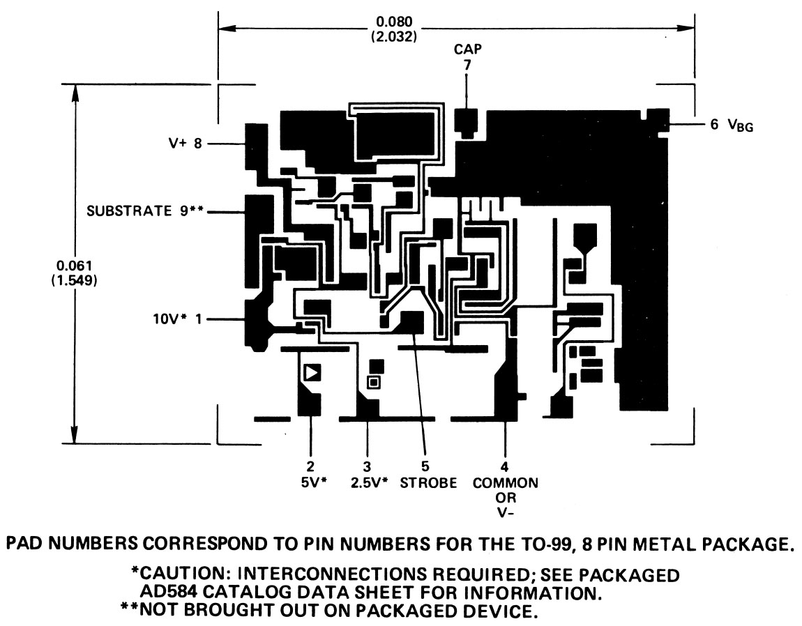
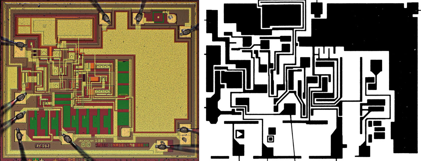
In the Analog Devices Data-Acquisition Databook from 1982, the metal layer of the Analog Devices AD584 is shown. This AD584 is slightly smaller than the Maxim model: 2,03mm x 1,55mm versus 2,2mm x 1,8mm.
You can see that the arrangement of the areas on the die is roughly the same. However, they are clearly two different designs.
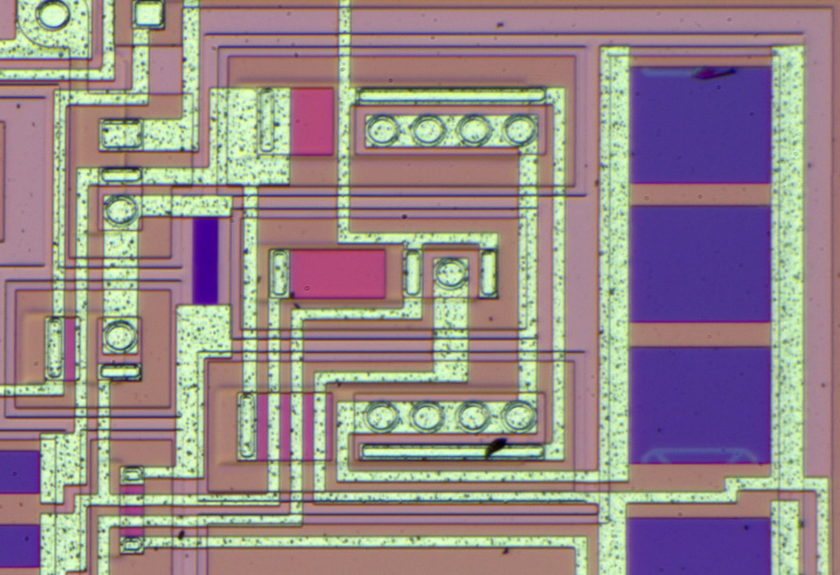
In the middle of the die, you immediately notice the typical bandgap structure, where a large transistor surrounds a small transistor. The ratio of the transistors here is 8:1. The working principle of a bandgap reference voltage source is described in more detail in the context of the AD1403 (
https://www.richis-lab.de/REF16.htm).
In the right area there are adjustable resistors. The traces of the adjustment are clearly visible. It is interesting that not only a simple cut was made at the lower resistor. An area was cut off whose ends describe a kind of triangle.
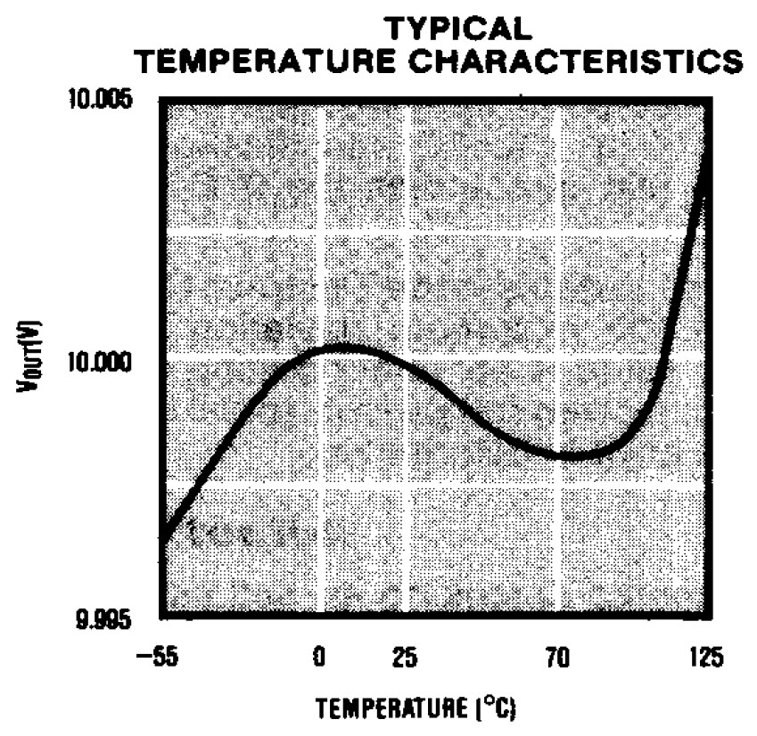
A bandgap reference compensates the negative temperature coefficient of the forward voltage of a pn junction with the positive temperature coefficient of the thermoelectric voltage of a pn junction. The datasheet of the AD584 shows the temperature variation of the output voltage and thus also that the compensation of the temperature coefficients is not perfect.
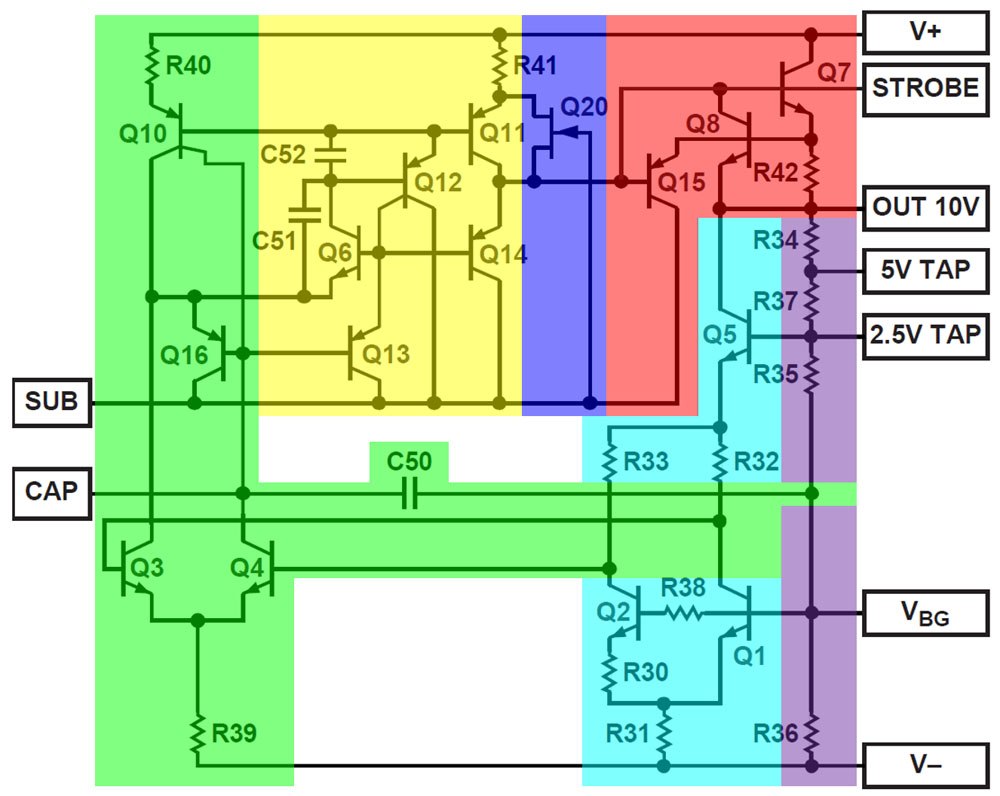
The datasheet from Analog Devices contains a complete circuit diagram for the AD584. As will become apparent, the circuit corresponds almost exactly to Maxim's circuit.
The core of the typical bandgap cell (cyan) is formed by the transistors Q1 and Q2. Q5 represents the associated current source. The 2,5V reference voltage is used to control this current source. This is also the reason why the datasheet points out that this node must not be trimmed more than 100mV.
The two branches of the bandgap reference are connected to a differential amplifier (green). The differential amplifier is supplied by Q10, which descripe two current sources. C50 reduces the noise of the reference output. For this reason, the package provides the CAP pin. Up to 100nF can be added externally between CAP and Vbg to further reduce noise.
The differential amplifier is followed by a somewhat unusual amplifier stage (yellow), at whose output is the push-pull stage Q11/Q14. C51 and C52 stabilise the circuit. It is interesting that this section is directly connected to the substrate. In principle, the substrate and the reference potential V- have the same potential, but the separation reduces the danger of disturbing feedback effects from the output driver to the reference voltage source.
Q20 (blue) ensures a safe start-up of the circuit. Q7 forms the output driver of the output stage (red). The output can be switched off with the strobe input. This pin is directly connected to the base of the output stage transistor. Q8 and R42 form an overcurrent protection. Transistor Q15 is a way of diverting the output current from Q7, which improves the control behaviour.
Below the 10V output is a resistor divider (purple) that maps the different output voltages.
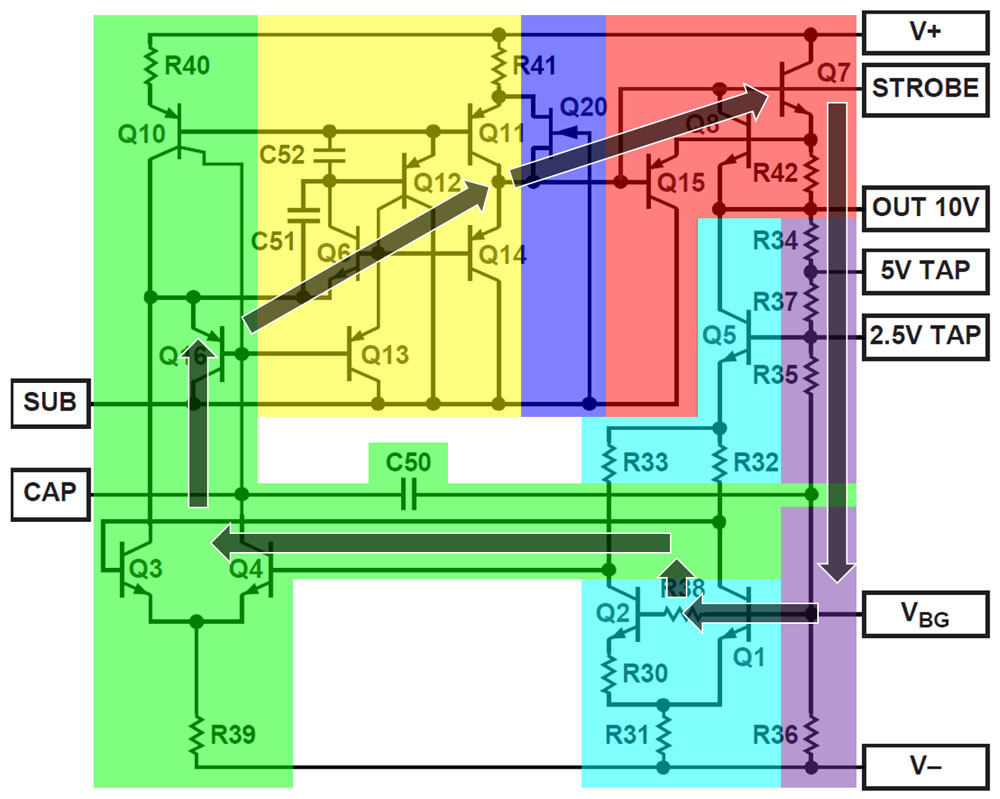
The control loop closes at the base of transistor Q1. At this point, the bandgap voltage is set at which the temperature coefficient becomes minimal. Since the control loop closes across the voltage divider, you can load the taps without changing the voltages. Of course, these taps are not as powerful as the 10V output. For this reason, you have to bridge outputs as described above if you want to fully load the lower output voltages.

All the elements of the Analog Devices circuit diagram can be found on the die. Only resistor R38 is missing. The base current of the transistors Q1/Q2 flows through the voltage divider at the output. It varies with the amplification factor and thus also with the temperature, which creates an additional temperature drift. The influence can be compensated by a resistor between the transistors. Alternatively, the voltage divider can be designed with as low an resistance as possible. Since the output is relatively powerful, the voltage divider could probably be chosen with sufficiently low resistance and thus do without the base resistor.
In the upper right corner of the die is the familiar square structure that can be used to set the adjustment process. The resistors R30 and R31, which define the temperature coefficient of the reference voltage, are adjusted. A testpad under R31 facilitates the adjustment. Resistors R34-R37, which define the value of the individual reference voltages, are also adjusted. The resistor R39 in the current sink of the differential amplifier and the collector resistors R23/R33 are made of the same material, but the geometries are much smaller. Presumably, the material was not chosen for balancing, but for other reasons.

The output stage (red) and the critical elements of the bandgap reference (green/cyan) are arranged in such a way that the heat dissipation of the output stage affects the two paths of the bandgap reference as equally as possible.
The upper of the two 10V bondpads is connected to the output stage. From the 10V pin, the second bondwire then leads to the voltage divider on the die. This also compensates for the voltage drop across the bondwires. The reference potential is connected to the substrate over the entire lower edge and half of the left edge (blue). Next to the output stage, there is also a large-area contact to the substrate. The bandgap reference is connected to the reference potential via the second bondwire so that it is not influenced by load currents.
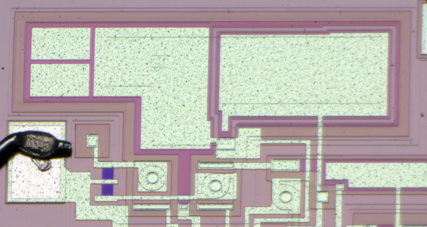
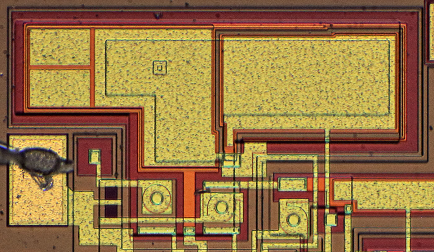
Capacitor C50 occupies almost half of the silicon area. In contrast, the capacitors C52 (left) and C51 (right) are much smaller. C51 is a classic capacitor, while C52 additionally uses the capacitance of the base-emitter junction. This can be seen in the contact window, which is visible in the metal layer. In the left area, the capacitance can be varied with two additional metal areas so that one can set an optimum between control speed and stability.
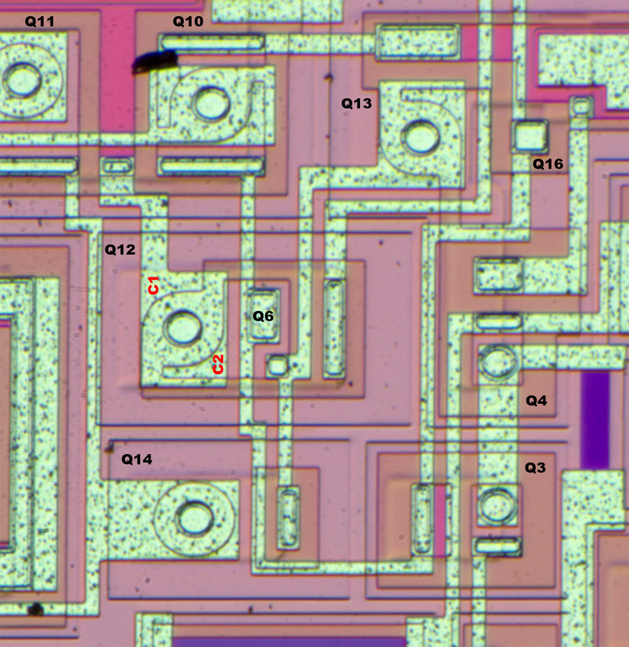
Usually, transistors are located in an n-doped well enclosed by p-doped regions. As long as the substrate has the most negative potential of the circuit, the wells are electrically isolated. This can be seen well in transistors Q3 and Q4, where the orange material represents the n-doping surrounded by the p-doping, which appears light pink. The slightly more prominent structures are p-doped frames that extend to the substrate.
As shown in the schematic, some transistors are directly connected to the substrate. This can be seen clearly in the case of transistor Q14, where the orange n-doping has only been introduced at the base contact. The collector is the p-doping surrounding all sides, which is directly connected to the substrate via the frame structure.
The transistor Q12 has two collectors. While C1 is directly connected to the substrate, as in Q14, C2 and its surroundings are somewhat more obscure. In the centre of the large metal surface is the circular, p-doped emitter, as usual for a PNP transistor. The ring around this circle is the n-doped base. The base area has been extended to the right and contains the p-doped collector C2, which is isolated from the substrate and is contacted in the lower right corner. In this p-doped collector area, an n-doping has again been introduced so that the NPN transistor Q6 can form there.
The PNP transistor Q16 is just as difficult to recognise. Here, the metal layer contacts a square, p-doped area that is completely covered by the metal layer. This area is located in an n-doped area, so that a substrate transistor is formed.
https://www.richis-lab.de/REF31.htm 