...
That is no 720A.... 
 I'd expect no 0.1ppm out of it, whatever it is
Heads up, TiN!
You'll restore this instrument, as precisely, as you've restored this wrecked 3458A.
Seems to be your fate--
And you will be able to check its 0.1ppm linearity by your 3458A (which is superior)
Frank
Very interesting thread with a lot of hi-res photos.
I have 4 720A and 2 of them had broken dec.A switch because the damage of the plastic joint inside, I have to fixed them by disassemble and glue.
Well, I put black wires on thick brown wire position, and now 1.0 input is 70.000K, 1.1 is 80.000K, on any A position. Closer, but not expected 100K.
Something else is off still.
Aha, I think I know what it is.
Taking second look on my pics and yours - all thin wire pairs from oil tank resistor network are shifted one position counterclockwise!
E.g. black thin wire pair should go to position 1, but goes to INPUT LO/R1047 shunt thing instead!
Lemme fix it!
Hi,
Captain Obvious says ' I think your unit has other wiring problems, It looks like one or two of the switches were changed'.
ManateeMafia
If the resistors didn't have '82 date codes, it looks like the kind of simplification that IET Labs might have made.
Does anybody have pictures of the inside of a KVD-700?
Link:
http://www.ietlabs.com/voltage-divider/kvd-700.htmlRegards,
Jay_Diddy_B
That was one of my initial thoughts but didn't see anything other than an oil can like the 720A in their current model. It may have been an initial attempt but decade A probably isn't good enough.
Don't quote me, but I was under impression that KVD-700 using BMF resistors. Remember reading that somewhere.
Swapped wiring +1 position, it's now 80K on 1.0 input and 90K on 1.1. We getting there, lol.
It also have now fixed 40k on output, does not matter which dials i set.
Fixed 1:2 divider!

All parts seem to be originally from FLUKE.
Decade B (and maybe also C) seem to be replaced in 1998 or later, but the technician failed to do it right and randomly soldered wires in the wrong places.
(And he made horrible solder joints, btw.)
As far as I can see in the pictures, the basic circuitry is unchanged..
Well he only changed a part of the wires of DEC A, left (seen from back of switch) of the brown wire, seemed to be ok., so maybe 3 or four pairs to the right were wrong, only
Frank
It also have now fixed 40k on output, does not matter which dials i set.
Fixed 1:2 divider!
I thought someone was trying to build a random voltage divider. My bad.
TiN,
would any more pictures help?
Jay_Diddy_B
Measured resistances of oiltank.
25-26 is 250 ohm. If i switch S1 to CAL and S8 to CK B (opening 25-26 R313-R314) they read 24.78K.
14-13, 12-11, 10-9 are each 103.7 ohm.
Rest of resistors are expected 9.896K
Measured resistances of oiltank.
25-26 is 250 ohm.
14-13, 12-11, 10-9 are each 103.7 ohm.
Rest of resistors are expected 9.896K
Is this with the wire disconnected from the oil tank?
You might want to disconnect the wires.
You don't want the problem to be in TiN can. (sorry)
Jay_Diddy_B
All wires are intact. And it should read correct value, as it's just series resistor chain.
I updated previous post, R313-314 are ok.
Positions on decade A switch from .6 (blue wire) to .4 (orange) are dead short.
TiN,
I am suggesting that you remove the wires from the oil can to check the resistors. This to make sure that wiring errors by the previous owner aren't messing with the readings.
Jay_Diddy_B
I think it's safe to say problem on the switch. I don't want to apply any heat on oil can. It's not necessary

I checked my spare switch from Dec.A bought before - no shorts on those pins. So I'll just replace switch next time.
I highly doubt the oil tank resistors would fail by going low. Resistors tend to go high or open circuit when they fail. Definitely think this is the bodge wiring from the previous "repair"
Here's good switch photo. I'll install this one and take apart faulty to see what's wrong with it. I think the brush finger got damaged and likely one of brush leaves is just stuck across three adjacent contacts.
This is what my crystal ball shows, at least.
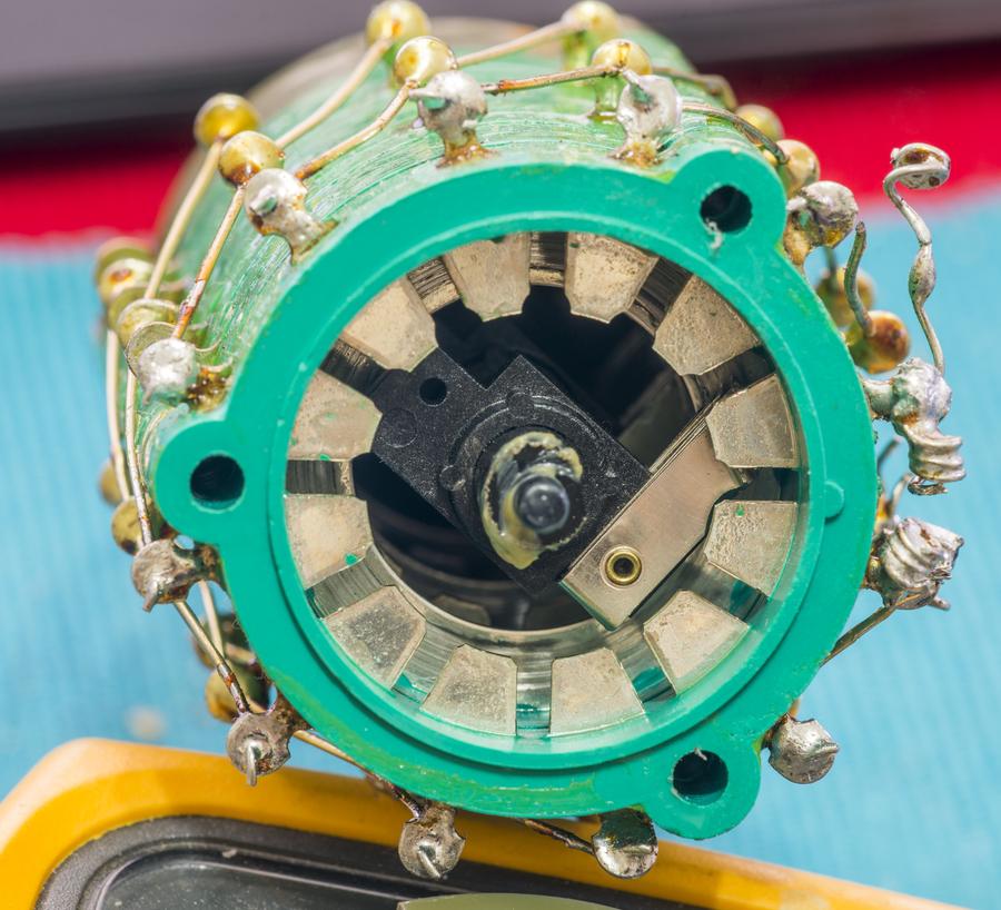
As you can see, no shorts across three positions should be there in any way. So switch is shorting oil tank resistors via trimmer resistors. Hence the 103.x ohm reading across oil 9K resistor.
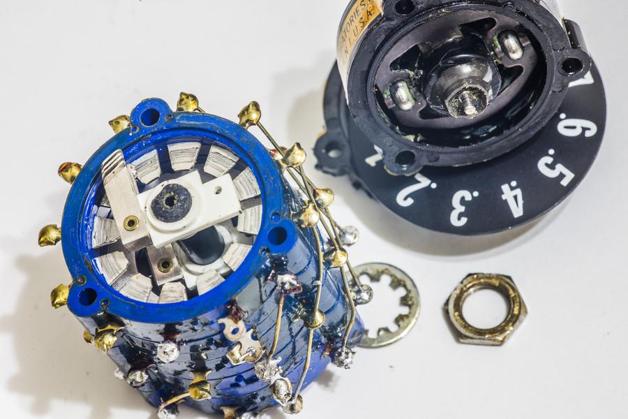
Also acrylic holders for rotary knob shafts are cracked and damaged on decades D and E, so i'll have to replace those too. I'll have to find where did I toss them.
I recently picked up a second "720A" from an auction recently. I grabbed it for parts so wasn't expecting much.
I wanted to make some comparison measurements for TiN but something is definitely wrong here.... FYI, all resistors have 82 datecodes. No mica ww in this beast. Anybody recognize the sig on the backside of the pcb's?
The pics I uploaded are from 720A #1.
interesting. Those resistors appear to be kelvin hermetic WW resistors. I believe that either the high end datron/Solartrons used them.
Looking at the oil tank filling port 'plug' , the cap screw seems out of place as a plug that fluke would have used not sure without peeking inside another one !.
TiN has showed us his oil plug, here is a picture of mine:
I think they look pretty similar.
Regards,
Jay_Diddy_B
Ah yes I also had a look at an old 720a at work and indeed the cap screw is normal ! (was wondering before if the oil tank had been tampered with given the 'other stuff' thats been done.)
Anyway while I was looking I took some more pictures for reference if needed.
One interesting mechanical failure which I suspect most of these oldies suffer from is the acrylic standoffs craze then crack and fall apart. see pic.
I just found pictures of my 720A.
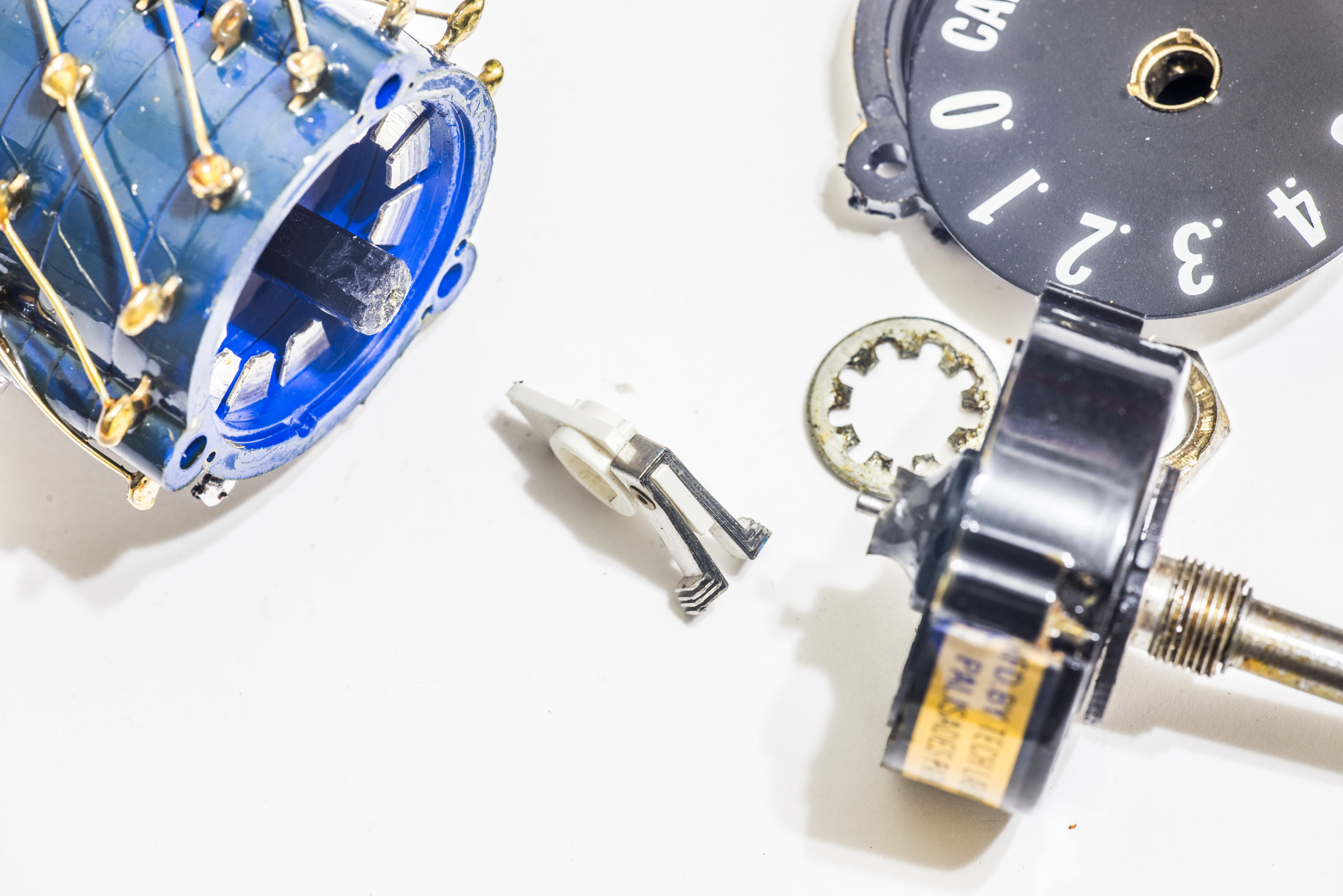
I've got original switch out. It immediately fallen apart in front section.

I think it's not supposed to be like that, and shaft supposed to be one long plastic driver. Perhaps someone tried to glue it together before?
Meh, anyone can help to confirm where thick green/white wire goes on Dec.A switch? Is it same as thick red from Dec.B ?
I think it's not supposed to be like that, and shaft supposed to be one long plastic driver. Perhaps someone tried to glue it together before?
It broke at exactly the same position as mine. Apparently, they use several brushes and more force on the brushes to minimize the contact resistance, therefore easy to break the shaft joint because more torque is needed to operate the switch.