I have a very intermittent issue, which happens only on one of two "identical" systems.
I am using DMA to feed SPI3 TX. Very simple!
This is the code
/*
*
* DMA-only version of HAL_SPI_TransmitReceive() but fixed for SPI3 and xx-only options added.
*
* For use where fast transfers are needed, on the limit of SPI3 speed so with zero gaps. This is impossible
* to do by polling at 10.5mbps or 21mbps and is probably marginal at 5.25mbps. The 16 bit SPI mode just
* manages gap-free with polling but works only with even block sizes, and has the "first byte problem" which
* DMA gets around.
*
* ** DMA ONLY SO NO CCM ACCESS SO THE TWO BUFFERS HAVE TO BE "STATIC" **
*
* This function is blocking so the caller can set CS=1 right away (check device data sheet!). A non-blocking
* version would make sense only if transmitting only (txonly=true) but the caller would have to tidy up
* the DMA and SPI3->CR2.
*
* spi3_set_mode() can still be used to set up the clock speed, phase, etc; this function does nothing
* to SPI3 other than to enable/disable DMA. It does however make sense only if SPI3 is a Master.
*
* Two modes, obviously mutually exclusive, for tx-only and rx-only:
* If txonly, dumps rx data so you don't need to allocate a buffer for it
* If rxonly, transmits all-0x00 so you don't need to feed SPI with some "known garbage"
*
* The rx-only mode is superfluous in most cases but it does avoid shifting non-0x00 data to the device
* while we are reading data out of it. With some devices this can matter. The ADS1118 ADC is one such.
*
* Because this function needs to work with KDE_spi3_set_mode(), care is taken to not modify the SPI config.
*
* NULL pointers are allowed if using the txonly or rxonly modes; then the unused one can be NULL.
*
*
*/

bool SPI3_DMA_TransmitReceive(uint8_t *pTxData, uint8_t *pRxData, uint16_t Size, bool txonly, bool rxonly, bool yield)
{

  	// Check for invalid inputs

	if ( Size==0 ) return (false);
  	if ( (pTxData==NULL) && !rxonly ) return (false);
  	if ( (pRxData==NULL) && !txonly ) return (false);

	uint32_t txadd = (uint32_t) pTxData;
	uint32_t rxadd = (uint32_t) pRxData;
	static uint8_t txonly_target=0;					// must not be in CCM
	static uint8_t rxonly_source=0;					// must not be in CCM

	// DMA ch 1 clock enable already done in b_main.c
	//RCC->AHB1ENR |= (1u << 21);					// DMA1EN=1 - DMA1 clock enable
	//hang_around_us(1);							// give it a chance to wake up

	// DMA1 Ch 0 Stream 0 is SPI3 RX

	DMA1_Stream0->CR = 0;							// disable DMA so all regs can be written

	DMA1->LIFCR = (0x03d << 0);					// clear int flags & transfer complete - 111101 stream 0

	DMA1_Stream0->NDTR = Size;

	if (txonly)
	{
		DMA1_Stream0->M0AR = (uint32_t) &txonly_target;		// memory address to dump rx data to
	}
	else
	{
		DMA1_Stream0->M0AR = rxadd;					// memory address in normal mode
	}

	DMA1_Stream0->PAR = (uint32_t) &(SPI3->DR);		// peripheral address
	DMA1_Stream0->FCR = 0;							// direct mode

	if (txonly)
	{
		DMA1_Stream0->CR = 0 << 25					// CHSEL: ch 0
						|  0 << 23			  		// MBURST: memory burst - single transfer
						|  0 << 21					// PBURST: peripheral burst - single transfer
						|  3 << 16					// PL: highest priority
						|  0 << 15					// PINCOS: no peripheral address increment offset
						|  0 << 13					// MSIZE: memory data size: byte
						|  0 << 11					// PSIZE: peripheral data size: byte
						|  0 << 10					// MINC: memory address increment: 0
						|  0 << 9					// PINC: peripheral address increment: 0
						|  0 << 8					// CIRC: no circular mode
						|  0 << 6					// DIR: peripheral to memory
						|  0 << 5					// PFCTRL: DMA is flow controller
						|  1 << 0;					// EN: enable stream
	}
	else
	{
		DMA1_Stream0->CR = 0 << 25					// CHSEL: ch 0
						|  0 << 23			  		// MBURST: memory burst - single transfer
						|  0 << 21					// PBURST: peripheral burst - single transfer
						|  3 << 16					// PL: highest priority
						|  0 << 15					// PINCOS: no peripheral address increment offset
						|  0 << 13					// MSIZE: memory data size: byte
						|  0 << 11					// PSIZE: peripheral data size: byte
						|  1 << 10					// MINC: memory address increment: 1
						|  0 << 9					// PINC: peripheral address increment: 0
						|  0 << 8					// CIRC: no circular mode
						|  0 << 6					// DIR: peripheral to memory
						|  0 << 5					// PFCTRL: DMA is flow controller
						|  1 << 0;					// EN: enable stream
	}

	// DMA1 Ch 0 Stream 7 is SPI3 TX

	DMA1_Stream7->CR = 0;							// disable DMA so all regs can be written

	DMA1->HIFCR = (0x03d << 22);					// clear int flags & transfer complete - 111101 stream 7

	DMA1_Stream7->NDTR = Size;

	if (rxonly)
	{
		DMA1_Stream7->M0AR = (uint32_t) &rxonly_source;		// memory address to fetch dummy tx data from
	}
	else
	{
		DMA1_Stream7->M0AR = txadd;					// memory address in normal mode
	}

	DMA1_Stream7->PAR = (uint32_t) &(SPI3->DR);		// peripheral address
	DMA1_Stream7->FCR = 0;							// direct mode

	if (rxonly)
	{
		DMA1_Stream7->CR = 0 << 25					// CHSEL: ch 0
						|  0 << 23			  		// MBURST: memory burst - single transfer
						|  0 << 21					// PBURST: peripheral burst - single transfer
						|  0 << 16					// PL: priority low
						|  0 << 15					// PINCOS: no peripheral address increment offset
						|  0 << 13					// MSIZE: memory data size: byte
						|  0 << 11					// PSIZE: peripheral data size: byte
						|  0 << 10					// MINC: memory address increment: 0
						|  0 << 9					// PINC: peripheral address increment: 0
						|  0 << 8					// CIRC: no circular mode
						|  1 << 6					// DIR: memory to peripheral
						|  0 << 5					// PFCTRL: DMA is flow controller
						|  1 << 0;					// EN: enable stream
	}
	else
	{
		DMA1_Stream7->CR = 0 << 25					// CHSEL: ch 0
						|  0 << 23			  		// MBURST: memory burst - single transfer
						|  0 << 21					// PBURST: peripheral burst - single transfer
						|  0 << 16					// PL: priority low
						|  0 << 15					// PINCOS: no peripheral address increment offset
						|  0 << 13					// MSIZE: memory data size: byte
						|  0 << 11					// PSIZE: peripheral data size: byte
						|  1 << 10					// MINC: memory address increment: 1
						|  0 << 9					// PINC: peripheral address increment: 0
						|  0 << 8					// CIRC: no circular mode
						|  1 << 6					// DIR: memory to peripheral
						|  0 << 5					// PFCTRL: DMA is flow controller
						|  1 << 0;					// EN: enable stream
	}

	// Config SPI3 to let DMA handle the data. These need to be cleared when transfer complete!
	// This starts the transfer

	SPI3->CR2 |= 3;									// TXDMAEN, RXDMAEN: 11 - both set in one go
	SPI3->CR1 |= (1<<6);							// SPE=1 enable SPI

	// Wait for DMA to finish. Blocking is necessary to prevent device CS=1 too early.
	// There could be a timeout here but a failure is impossible short of duff silicon, because
	// we are a Master and generating the SPI clock.

	while(true)
	{

		// Either end-transfer detection method below works but the NDTR one may be more reliable
#if 1
		uint16_t temp1;
		temp1 = DMA1_Stream0->NDTR;
		if ( temp1 == 0 ) break;					// transfer count = 0
#else
		uint32_t temp2;
		temp2 = DMA1->LISR;
		if ( (temp2 & (1<<5)) !=0 ) break;			// TCIF0
#endif

	}

	SPI3->CR2 &= ~3;								// TXDMAEN, RXDMAEN: 00 - both cleared in one go

	// Clear int pending flags. They get cleared at the top of this function anyway, but...

	DMA1->LIFCR = (0x03d << 0);						// clear int flags & transfer complete - 111101 stream 0
	DMA1->HIFCR = (0x03d << 22);					// clear int flags & transfer complete - 111101 stream 7

    // Clear any rx data and the overrun flag in case not all received data was read

	SPI3->CR1 &= ~(1<<6);							// SPE=0 disable SPI

	//hang_around_us(1);
   	SPI3->DR;
	SPI3->DR;
   	SPI3->SR;

   	return (true);

}
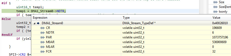
When it hangs, it hangs in that forever loop near the end. Breaking the code there shows NDTR=6; init value was 7 so it looks like it moved 1 byte. In
	SPI3->CR2 |= 3;								// TXDMAEN, RXDMAEN: 11 - both set in one go
	SPI3->CR1 |= (1<<6);							// SPE=1 enable SPI
the relevant bits are correctly set ie both DMA and SPI are enabled.
rxonly=false (txonly mode is used)
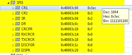
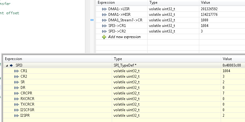
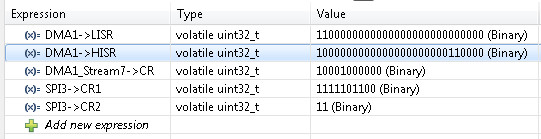
CR=10001000000
CR2=3
CR1=1111101100
NDTR=6
Notably, CR has bit 0 = 0 so
1 << 0; // EN: enable stream
has got cleared, but how? What else can clear DMA1_Stream7->CR bit 0???
SPI3 access is mutexed. DMA access isn't but nothing else should be using this DMA channel. Is bit 0 of CR somehow shared between multiple DMA "processes"?
This code has been running for many months, 24/7, solidly. What has changed? Well, I added an RTOS task which reads an ADS1118 ADC. This could use the above DMA like everything else does (for SPI3) but instead it uses the HAL_SPI_TransmitReceive() function, because the ADS1118 uses the SPI in 16 bit mode, and I didn't want to re-hack the DMA code to do that. The ADS1118 code was written and very carefully verified 2 years ago.
I am tempted to replace HAL_SPI_TransmitReceive() with a 16 bit DMA version. I also tried to use the above bytewide DMA code but for some reason it didn't work (I didn't forget the fact that in 16 bit mode, SPI transmits the MS byte first).
But the basic thing is CR bit 0 getting cleared, before NDTR has reached 0. How is that possible? Master SPI cannot just be stopped so DMA requests from it cannot just stop.
The calling code of that DMA function is a bit of code which feeds a 6 digit LED display controller, hence the 7 bytes getting transmitted. This has been working for years too. It runs at 10Hz. Every few minutes or hours, it gets stuck.
FWIW, this is the SPI3 function the ADS1118 uses. It is bloated with loads of junk. We had a thread on this before... it deals with the special condition of transfer count = 1. But I don't think this is the problem.
/**
  * @brief  Transmit and Receive an amount of data in blocking mode.
  * @param  hspi pointer to a SPI_HandleTypeDef structure that contains
  *               the configuration information for SPI module.
  * @param  pTxData pointer to transmission data buffer
  * @param  pRxData pointer to reception data buffer
  * @param  Size amount of data to be sent and received
  * @param  Timeout Timeout duration
  * @retval HAL status
  */
HAL_StatusTypeDef HAL_SPI_TransmitReceive(SPI_HandleTypeDef *hspi, uint8_t *pTxData, uint8_t *pRxData, uint16_t Size,
                                          uint32_t Timeout)
{
  uint16_t             initial_TxXferCount;
  uint32_t             tmp_mode;
  HAL_SPI_StateTypeDef tmp_state;
  uint32_t             tickstart;

  /* Variable used to alternate Rx and Tx during transfer */
  uint32_t             txallowed = 1U;
  HAL_StatusTypeDef    errorcode = HAL_OK;

  /* Check Direction parameter */
  assert_param(IS_SPI_DIRECTION_2LINES(hspi->Init.Direction));

  /* Process Locked */
  __HAL_LOCK(hspi);

  /* Init tickstart for timeout management*/
  tickstart = HAL_GetTick();

  /* Init temporary variables */
  tmp_state           = hspi->State;
  tmp_mode            = hspi->Init.Mode;
  initial_TxXferCount = Size;

  if (!((tmp_state == HAL_SPI_STATE_READY) || \
        ((tmp_mode == SPI_MODE_MASTER) && (hspi->Init.Direction == SPI_DIRECTION_2LINES) && (tmp_state == HAL_SPI_STATE_BUSY_RX))))
  {
    errorcode = HAL_BUSY;
    goto error;
  }

  if ((pTxData == NULL) || (pRxData == NULL) || (Size == 0U))
  {
    errorcode = HAL_ERROR;
    goto error;
  }

  /* Don't overwrite in case of HAL_SPI_STATE_BUSY_RX */
  if (hspi->State != HAL_SPI_STATE_BUSY_RX)
  {
    hspi->State = HAL_SPI_STATE_BUSY_TX_RX;
  }

  /* Set the transaction information */
  hspi->ErrorCode   = HAL_SPI_ERROR_NONE;
  hspi->pRxBuffPtr  = (uint8_t *)pRxData;
  hspi->RxXferCount = Size;
  hspi->RxXferSize  = Size;
  hspi->pTxBuffPtr  = (uint8_t *)pTxData;
  hspi->TxXferCount = Size;
  hspi->TxXferSize  = Size;

  /*Init field not used in handle to zero */
  hspi->RxISR       = NULL;
  hspi->TxISR       = NULL;

#if (USE_SPI_CRC != 0U)
  /* Reset CRC Calculation */
  if (hspi->Init.CRCCalculation == SPI_CRCCALCULATION_ENABLE)
  {
    SPI_RESET_CRC(hspi);
  }
#endif /* USE_SPI_CRC */

  /* Check if the SPI is already enabled */
  if ((hspi->Instance->CR1 & SPI_CR1_SPE) != SPI_CR1_SPE)
  {
    /* Enable SPI peripheral */
    __HAL_SPI_ENABLE(hspi);
  }

  /* Transmit and Receive data in 16 Bit mode */
  if (hspi->Init.DataSize == SPI_DATASIZE_16BIT)
  {
    if ((hspi->Init.Mode == SPI_MODE_SLAVE) || (initial_TxXferCount == 0x01U))
    {
      hspi->Instance->DR = *((uint16_t *)hspi->pTxBuffPtr);
      hspi->pTxBuffPtr += sizeof(uint16_t);
      hspi->TxXferCount--;
    }
    while ((hspi->TxXferCount > 0U) || (hspi->RxXferCount > 0U))
    {
      /* Check TXE flag */
      if ((__HAL_SPI_GET_FLAG(hspi, SPI_FLAG_TXE)) && (hspi->TxXferCount > 0U) && (txallowed == 1U))
      {
        hspi->Instance->DR = *((uint16_t *)hspi->pTxBuffPtr);
        hspi->pTxBuffPtr += sizeof(uint16_t);
        hspi->TxXferCount--;
        /* Next Data is a reception (Rx). Tx not allowed */
        txallowed = 0U;

#if (USE_SPI_CRC != 0U)
        /* Enable CRC Transmission */
        if ((hspi->TxXferCount == 0U) && (hspi->Init.CRCCalculation == SPI_CRCCALCULATION_ENABLE))
        {
          SET_BIT(hspi->Instance->CR1, SPI_CR1_CRCNEXT);
        }
#endif /* USE_SPI_CRC */
      }

      /* Check RXNE flag */
      if ((__HAL_SPI_GET_FLAG(hspi, SPI_FLAG_RXNE)) && (hspi->RxXferCount > 0U))
      {
        *((uint16_t *)hspi->pRxBuffPtr) = (uint16_t)hspi->Instance->DR;
        hspi->pRxBuffPtr += sizeof(uint16_t);
        hspi->RxXferCount--;
        /* Next Data is a Transmission (Tx). Tx is allowed */
        txallowed = 1U;
      }
      if (((HAL_GetTick() - tickstart) >=  Timeout) && (Timeout != HAL_MAX_DELAY))
      {
        errorcode = HAL_TIMEOUT;
        goto error;
      }
    }
  }
  /* Transmit and Receive data in 8 Bit mode */
  else
  {
    if ((hspi->Init.Mode == SPI_MODE_SLAVE) || (initial_TxXferCount == 0x01U))
    {
      *((__IO uint8_t *)&hspi->Instance->DR) = (*hspi->pTxBuffPtr);
      hspi->pTxBuffPtr += sizeof(uint8_t);
      hspi->TxXferCount--;
    }
    while ((hspi->TxXferCount > 0U) || (hspi->RxXferCount > 0U))
    {
      /* Check TXE flag */
      if ((__HAL_SPI_GET_FLAG(hspi, SPI_FLAG_TXE)) && (hspi->TxXferCount > 0U) && (txallowed == 1U))
      {
        *(__IO uint8_t *)&hspi->Instance->DR = (*hspi->pTxBuffPtr);
        hspi->pTxBuffPtr++;
        hspi->TxXferCount--;
        /* Next Data is a reception (Rx). Tx not allowed */
        txallowed = 0U;

#if (USE_SPI_CRC != 0U)
        /* Enable CRC Transmission */
        if ((hspi->TxXferCount == 0U) && (hspi->Init.CRCCalculation == SPI_CRCCALCULATION_ENABLE))
        {
          SET_BIT(hspi->Instance->CR1, SPI_CR1_CRCNEXT);
        }
#endif /* USE_SPI_CRC */
      }

      /* Wait until RXNE flag is reset */
      if ((__HAL_SPI_GET_FLAG(hspi, SPI_FLAG_RXNE)) && (hspi->RxXferCount > 0U))
      {
        (*(uint8_t *)hspi->pRxBuffPtr) = hspi->Instance->DR;
        hspi->pRxBuffPtr++;
        hspi->RxXferCount--;
        /* Next Data is a Transmission (Tx). Tx is allowed */
        txallowed = 1U;
      }
      if ((((HAL_GetTick() - tickstart) >=  Timeout) && ((Timeout != HAL_MAX_DELAY))) || (Timeout == 0U))
      {
        errorcode = HAL_TIMEOUT;
        goto error;
      }
    }
  }

#if (USE_SPI_CRC != 0U)
  /* Read CRC from DR to close CRC calculation process */
  if (hspi->Init.CRCCalculation == SPI_CRCCALCULATION_ENABLE)
  {
    /* Wait until TXE flag */
    if (SPI_WaitFlagStateUntilTimeout(hspi, SPI_FLAG_RXNE, SET, Timeout, tickstart) != HAL_OK)
    {
      /* Error on the CRC reception */
      SET_BIT(hspi->ErrorCode, HAL_SPI_ERROR_CRC);
      errorcode = HAL_TIMEOUT;
      goto error;
    }
    /* Read CRC */
    READ_REG(hspi->Instance->DR);
  }

  /* Check if CRC error occurred */
  if (__HAL_SPI_GET_FLAG(hspi, SPI_FLAG_CRCERR))
  {
    SET_BIT(hspi->ErrorCode, HAL_SPI_ERROR_CRC);
    /* Clear CRC Flag */
    __HAL_SPI_CLEAR_CRCERRFLAG(hspi);

    errorcode = HAL_ERROR;
  }
#endif /* USE_SPI_CRC */

  /* Check the end of the transaction */
  if (SPI_EndRxTxTransaction(hspi, Timeout, tickstart) != HAL_OK)
  {
    errorcode = HAL_ERROR;
    hspi->ErrorCode = HAL_SPI_ERROR_FLAG;
    goto error;
  }

  /* Clear overrun flag in 2 Lines communication mode because received is not read */
  if (hspi->Init.Direction == SPI_DIRECTION_2LINES)
  {
    __HAL_SPI_CLEAR_OVRFLAG(hspi);
  }

error :
  hspi->State = HAL_SPI_STATE_READY;
  __HAL_UNLOCK(hspi);
  return errorcode;
}
As I get it, you are using HAL and non-HAL versions to access the same SPI resource. HAL version has __HAL_LOCK(hspi), while non-HAL doesn't.
Could it be possible that two processes access SPI3 concurrently?
The difference between two "identical" systems could be slight timing variations.
The HAL_LOCK feature doesn't actually do anything useful. It is brain-dead code. One has to do that sort of thing properly i.e. with mutexes, and that is done.
SPI3 is shared among a number of devices, and is mutexed. But this is nothing new; this system (shared SPI3) has been running for ages. I even have different initialisation possible for each device (it keeps track of the "current device" and re-initialises if changed).
This issue is more weird, because we have the DMA enable bit getting cleared before NDTR reached 0, which should be impossible if feeding a
Master SPI channel. If you use DMA to move RAM -> SPI, the SPI does the DMA request for each transfer (8 or 16 bits, as configured), and an SPI cannot possibly (??) not do that transfer all the time it is enabled... It is like setting up a DMA-fed UART. It should just keep going until the DMA transfer count = 0.
I am wondering whether my understanding of the 32F4 DMA controller is incomplete and there are actually
shared registers. I know streams cannot be shared unless you do mutual-exclusive coding of some sort (they cannot run concurrently; a "stream" is just a system of multiple "data request" connections to the same DMA controller). This is my current DMA usage
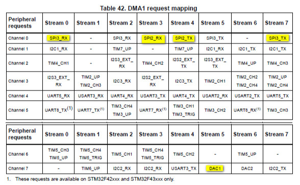
Stream 6 is not actually used but since I am feeding a 32 bit value to DAC1, this comes out of both DAC1 & DAC2. I don't think this is relevant.
FWIW, because the ADS1118 only ever gets 16 bits and concurrently returns 16 bits, I stripped down the HAL SPI function to just this
// Version of HAL_SPI_TransmitReceive but dedicated to ADS1118 usage.
// Transmits one 16 bit word and receives one 16 bit word back.
// Created to avoid the bloated HAL_SPI_TransmitReceive() function but still supporting 16 bit mode.
// SPI3 must already be initialised appropriately e.g. clock speed, 16 bit mode.

void SPI3_TransmitReceive_16(uint16_t ValueIn, uint16_t * ValueOut)
{

	// enable SPI3

	SPI3->CR1 |= SPI_CR1_SPE;

  	// Transmit the 16 bit word

	SPI3->DR = (uint32_t) ValueIn;

	// Wait until a 16 bit word comes back. This cannot hang if the SPI is a Master. You always get back what you sent.

	while (true)
	{
		if ( (SPI3->SR & 1) != 0 )		// if ((__HAL_SPI_GET_FLAG(hspi, SPI_FLAG_RXNE)) etc
		{
			*ValueOut = (uint16_t) SPI3->DR;
			break;
		}
	}

	// Clear any rx data and the overrun flag in case not all received data was read.
	// A small delay is needed because the very last transfer may not propagate to DR.

	hang_around_us(1);
	SPI3->DR;
	SPI3->DR;
	SPI3->SR;

}
The code is running fine but it's been only an hour or two.
I recall a bug when using more than 2 dmas concurrently, not sure what models were affected.
A lot of forums are migrating to Markdown syntax.
I got angry at first (Why reinvent the wheel, need to relearn everything again, etc) but I must admit I ended liking it.
Page 16 here
And even
better, directing straight to the chapter in question.
And even better, directing straight to the chapter in question.
Cool, how did you generate that link?
Cool, how did you generate that link?
Followed the original link --> scrolled to page 2 "Contents" --> right-clicked on "2.1.10 DMA2 ..." --> "Copy link" in the context menu --> pasted it here.
Apparently, this will work only if the link in the table of contents exists.
What are you seeing in the DMA status register when this fails? From the reference manual:
If the TEIFx or the FEIFx flag is set due to incompatibility between burst size and FIFO threshold level, the faulty stream is automatically disabled through a hardware clear of its EN bit in the corresponding stream configuration register (DMA_SxCR).
That's really interesting - a method whereby the DMA could clear the EN bit.
The wording in the RM is
If the TEIFx or the FEIFx flag is set due to incompatibility between burst size and FIFO
threshold level, the faulty stream is automatically disabled through a hardware clear of its
EN bit in the corresponding stream configuration register (DMA_SxCR).
I have
		DMA1_Stream7->CR = 0 << 25					// CHSEL: ch 0
						|  0 << 23			  		// MBURST: memory burst - single transfer
						|  0 << 21					// PBURST: peripheral burst - single transfer
						|  0 << 16					// PL: priority low
						|  0 << 15					// PINCOS: no peripheral address increment offset
						|  0 << 13					// MSIZE: memory data size: byte
						|  0 << 11					// PSIZE: peripheral data size: byte
						|  1 << 10					// MINC: memory address increment: 1
						|  0 << 9					// PINC: peripheral address increment: 0
						|  0 << 8					// CIRC: no circular mode
						|  1 << 6					// DIR: memory to peripheral
						|  0 << 5					// PFCTRL: DMA is flow controller
						|  1 << 0;					// EN: enable stream
and this works, so how can there be an error sometimes?
The EN bit must have been set initially for NDTR to go down from 7 to 6.
Unfortunately, having rewritten the huge chunk of ST HAL SPI code to just the bare minimum (further above) I have not been able to make it go wrong. The interface to this DAC is just single 16 bit words so I have the very minimal function now.
Nothing else should be using the same stream.
Also in the RM:
In direct mode (when the DMDIS value in the DMA_SxFCR register is ‘0’), the threshold
level of the FIFO is not used: after each single data transfer from the peripheral to the FIFO,
the corresponding data are immediately drained and stored into the destination.
and I am using direct mode
	DMA1_Stream7->PAR = (uint32_t) &(SPI3->DR);		// peripheral address
	DMA1_Stream7->FCR = 0;							// direct mode
You haven't answered this:
What are you seeing in the DMA status register when this fails?
Also, what's in the memory address register of said stream at that moment?
JW
After removing HAL_SPI_TransmitReceive (ADS1118 code; uses 16 bit SPI mode and
polled data transfer) the code runs 100% reliably, so to make it fail I put in that crappy code back, and got this from breaking the hanging code. This break is in
DMA code feeding a STLED316 chip which is fed with 7 bytes and whose NDTR was stuck at 6 as mentioned previously.
Hard to see how the polled HAL_SPI_TransmitReceive, feeding a single 16 bit word to SPI3, can bugger up the DMA channel feeding seven bytes to another chip, with the SPI activity being mutexed, but here we are... Maybe HAL_SPI_TransmitReceive is doing some funny SPI config which causes the SPI to do just 1 DMA request?
HAL_SPI_TransmitReceive is a load of junk and I have gradually been binning these HAL functions over the last 2+ years. I moved all instances of HAL_SPI_TransmitReceive to using the above-posted
DMA code which runs solidly, with about 10 different devices. But for the ADS1118 I am using 16 bit SPI mode so I am not currently using DMA and just use a simple polled function
// Version of HAL_SPI_TransmitReceive but dedicated to ADS1118 usage.
// Transmits one 16 bit word and receives one 16 bit word back.
// Created to avoid the bloated HAL_SPI_TransmitReceive() function but still supporting 16 bit mode.
// SPI3 must already be initialised appropriately e.g. clock speed, 16 bit mode.

void SPI3_TransmitReceive_16(uint16_t ValueIn, uint16_t * ValueOut)
{

	// enable SPI3

	SPI3->CR1 |= SPI_CR1_SPE;

  	// Transmit the 16 bit word

	SPI3->DR = (uint32_t) ValueIn;

	// Wait until RXNE=1 and get the 16 bit value out

	while ( (SPI3->SR & 1) == 0 ) {}
	*ValueOut = (uint16_t) SPI3->DR;

	// Clear any rx data and the overrun flag in case not all received data was read.
	// A small delay is needed because the very last transfer may not propagate to DR.

	hang_around_us(1);
	SPI3->DR;
	SPI3->DR;
	SPI3->SR;

}
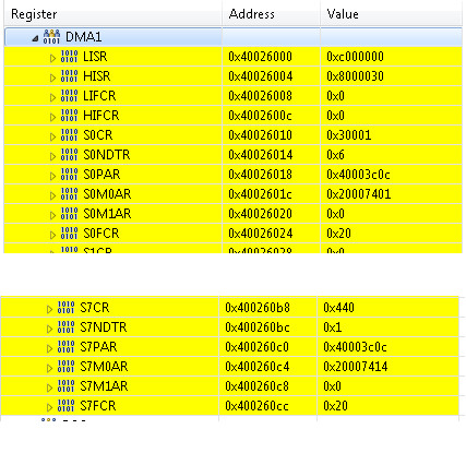
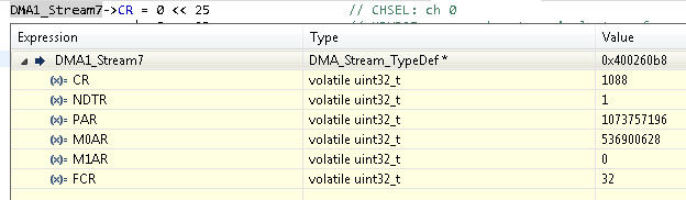
Anyway, the registers:
M0AR = 0x20007401 (not in CCM; looks right)
PAR = 0x40003c0c (SPI3 DR)
FCR = 100000
CR = 110000000000000001
NDTR = 6 (initial load value = 7 so DMA did start and moved just 1 byte)
LIFCR = HIFCR = 0
No idea how to find any SR; there is no DMA1_Stream0->SR
No idea how to find any SR; there is no DMA1_Stream0->SR
DMA_LISR or DMA_HISR holds the TEIFx and FEIFx flags, depending on the stream in use.
OK so is the stream enabled or disabled?
You are using two DMA streams so post content of registers for both. And the SPI registers, too. Screenshots from the IDE are OK. Also, what do you observe on the signals?
DMA_LISR or DMA_HISR holds the TEIFx and FEIFx flags, depending on the stream in use.
... content of these (both) too.
JW
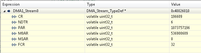
I can't get why NDTR is not the same for the two streams.
I haven't worked out how to make Cube show all values in hex or binary.
Also, what do you observe on the signals?
Feeding the SPI is obviously on-chip. I could monitor the ADS1118 and STLED316 signals but that takes a lot of setting up and it is much much faster to sidestep this problem by not using HAL_SPI_TransmitReceive().
If anyone can see any hints in the config, I will happily try a few things. Thank you!
My money is on HAL_SPI_TransmitReceive() having some side effect, because I stopped using it about a year ago (switched all SPI stuff to DMA) and this problem turned up only when I dug up the ADS1118 code after not using it for a couple of years, and this code uses HAL_SPI_TransmitReceive() (which nothing else uses) to send and receive a single 16 bit word.
Someone else did the ADS1118 code (he used the HAL funcs for most things) and it took him a good number of days to get the ADS1118 to work. It is an unusual device. I tried just now to use my DMA code for it but failed and decided to do something more useful, then replaced HAL_SPI_TransmitReceive() with my trivial 16 bit polled SPI function (above).
OMG how can you set values display to decimal? Do you expect us to convert?
[EDIT] OK now I see you've already wrote about it... still, how can you work with it like that?
[EDIT2] Went through those numbers and can't see anything obviously wrong, sorry.
JW
I have to click on them one at a time to see other formats.
The others are "mouseover" popups and I can't see where the config for the number formats is. Sorry!
Use SFR view, you'll see the bitfields organization, with names and descriptions.
So, if you use SPI3 also elsewhere, after you've finished with it and before setting it up for DMA, do you disable it by clearing SPI3_CR1.SPE?
JW
This is the latter part of my DMA code, and SPI gets disabled via CR1 and CR2
	// Config SPI3 to let DMA handle the data. These need to be cleared when transfer complete!
	// This starts the transfer

	SPI3->CR2 |= 3;									// TXDMAEN, RXDMAEN: 11 - both set in one go
	SPI3->CR1 |= (1<<6);							// SPE=1 enable SPI

	// Wait for DMA to finish. Blocking is necessary to prevent device CS=1 too early.
	// There could be a timeout here but a failure is impossible short of duff silicon, because
	// we are a Master and generating the SPI clock.

	while(true)
	{

		// Either end-transfer detection method below works but the NDTR one may be more reliable
#if 1
		uint16_t temp1;
		temp1 = DMA1_Stream0->NDTR;
		if ( temp1 == 0 ) break;					// transfer count = 0
#else
		uint32_t temp2;
		temp2 = DMA1->LISR;
		if ( (temp2 & (1<<5)) !=0 ) break;			// TCIF0
#endif
		if (yield) osDelay(1);						// release to RTOS (see notes in comments)

	}

	SPI3->CR2 &= ~3;								// TXDMAEN, RXDMAEN: 00 - both cleared in one go

	// Clear int pending flags. They get cleared at the top of this function anyway, but...

	DMA1->LIFCR = (0x03d << 0);						// clear int flags & transfer complete - 111101 stream 0
	DMA1->HIFCR = (0x03d << 22);					// clear int flags & transfer complete - 111101 stream 7

    // Clear any rx data and the overrun flag in case not all received data was read

	SPI3->CR1 &= ~(1<<6);							// SPE=0 disable SPI

	//hang_around_us(1);
   	SPI3->DR;
	SPI3->DR;
   	SPI3->SR;

   	return (true);

}
However AFAICS HAL_SPI_TransmitReceive() does not disable SPI, does it? And neither does my short function, so I need to do that as shown:
// Version of M_HAL_SPI2_TransmitReceive but dedicated to ADS1118 usage.
// Transmits one 16 bit word and receives one 16 bit word back.
// Created to avoid the bloated HAL_SPI_TransmitReceive() function but still supporting 16 bit mode.
// SPI3 must already be initialised appropriately e.g. clock speed, 16 bit mode.

void SPI3_TransmitReceive_16(uint16_t ValueIn, uint16_t * ValueOut)
{

	// enable SPI3

	SPI3->CR1 |= SPI_CR1_SPE;

  	// Transmit the 16 bit word

	SPI3->DR = (uint32_t) ValueIn;

	// Wait until RXNE=1 and get the 16 bit value out

	while ( (SPI3->SR & 1) == 0 ) {}
	*ValueOut = (uint16_t) SPI3->DR;

	// Clear any rx data and the overrun flag in case not all received data was read.
	// A small delay is needed because the very last transfer may not propagate to DR.

	hang_around_us(1);
	SPI3->DR;
	SPI3->DR;
	SPI3->SR;

	SPI3->CR1 &= ~SPI_CR1_SPE;   // disable SPI3

}
And my DMA-SPI function does not disable SPI3 prior to loading up the DMA. Probably a good idea. But can one config an SPI channel with it disabled? I know one can't do so with the clock disabled.