-
Let's discuss tellurium's tutorial
Posted by
wek
on 27 Sep, 2022 14:24
-
-
#1 Reply
Posted by
wek
on 27 Sep, 2022 14:25
-
-
#2 Reply
Posted by
peter-h
on 27 Sep, 2022 14:28
-
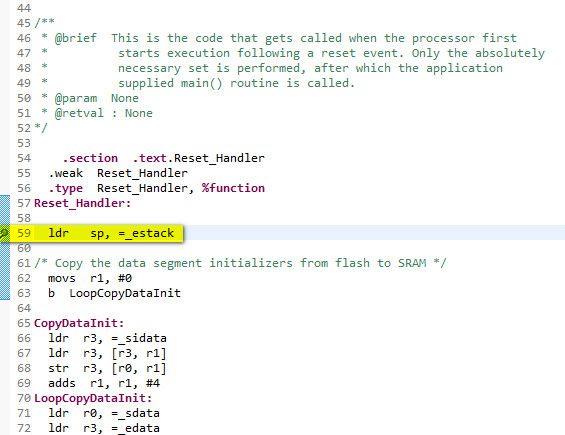
ENTRY does something. This is the start of my linker script
/* Entry Point */
ENTRY(Reset_Handler)

/* Reference boot block stuff to ensure that it gets linked-in - not sure if these do anything */
/* EXTERN(b_main) */
/* EXTERN(KDE_loader) */
/* EXTERN(KDE_main_stub) */
and the commented-out stuff definitely does nothing. But removing ENTRY causes the code to bomb immediately.
However, if I restart the code (in Cube) it runs fine. So the bombing occurs only after a debugger code load and reset release. A restart within Cube runs ok.
100% repeatable.
Even if I put a breakpoint here, it bombs after a debugger load
-
#3 Reply
Posted by
eutectique
on 27 Sep, 2022 15:39
-
I've just noticed Remove ENTRY() from the linker script
Can you please elaborate?
ENTRY() is only meaningful for creating and debugging the ELF file. It does nothing for binary (or hex, or srec for that matter) which is generated from ELF file -- the start address is the second word in the vector table for Cortex-M CPUs.
-
#4 Reply
Posted by
eutectique
on 27 Sep, 2022 18:15
-
Let's discuss tellurium's tutorial
Really well written.
Maybe I'd create a PR one day for:
- semihosting
- LLVM/Clang instead of GCC
-
#5 Reply
Posted by
tellurium
on 27 Sep, 2022 21:28
-
Can you please elaborate?
A linker script is an instruction, how to create an executable ELF file.
An executable ELF has a so-called "entry point" in the ELF header.
THat's used by an OS as starting address, when OS loads an executable.
In our case, firmware startup mechanism does not use an ELF header's entry point. Instead, a vector table is used to specify an entry point.
The generated .bin file is the same with, or without the ENTRY instruction, because the objcopy command simply extracts .text & .data section and concatenates them into a .bin file - and an entry point address gets ignored.
So if firmware.bin file is used for reflash, the ENTRY instruction is not used and makes no difference.
That said, apparently the Ozone debugger, if it is pointed to firmware.elf file, does use the entry point address, and does not work properly without the ENTRY instruction. Maybe the same stands for other debuggers like Cube/Eclipse. So, if a reflash method uses .elf file, the entry point is required.
I have reverted the ENTRY removal, to make it work in any case.
-
#6 Reply
Posted by
tellurium
on 27 Sep, 2022 21:44
-
-
#7 Reply
Posted by
wek
on 27 Sep, 2022 22:04
-
That said, apparently the Ozone debugger, if it is pointed to firmware.elf file, does use the entry point address, and does not work properly without the ENTRY instruction. Maybe the same stands for other debuggers like Cube/Eclipse. So, if a reflash method uses .elf file, the entry point is required.
Thanks, that probably explains Peter's finidings posted above, too.
JW
-
#8 Reply
Posted by
newbrain
on 28 Sep, 2022 07:38
-
Let's discuss tellurium's tutorial
Really well written.
Maybe I'd create a PR one day for:
- semihosting
- LLVM/Clang instead of GCC
Quite interesting tutorial, and good progression from DS + gcc to CMSIS.
The first obstacle for LLVM/clang is that the reset code won't compile, as clang only allows basic asm in naked functions.
"Dressing" the function will only have the drawback of (possibly) wasting some words in the stack, though.
-
#9 Reply
Posted by
peter-h
on 28 Sep, 2022 07:46
-
The STLINK debuggers use the ELF file.
-
#10 Reply
Posted by
wek
on 28 Sep, 2022 08:17
-
- semihosting
- LLVM/Clang instead of GCC
I think, what is also missing: IRQ handlers with defaults using weak symbols, IRQ priorities, and setting up clocks.
Maybe, a DMA example would be nice to have, too, with UART/SPI.
Yes, maybe all that, but...
How to do things so that they won't fall into TLDR cathegory? A tutorial maybe shouldn't take more to read than is time to install an IDE?
Maybe a thick line saying "this is it, what follows is advanced topics" would do the trick?
JW
-
#11 Reply
Posted by
peter-h
on 28 Sep, 2022 08:31
-
Setting up clocks is essential though.
These CPUs power-up at 16MHz but almost nobody runs them at 16MHz. One dives straight to the PLL to get 168MHz or whatever.
The following is my condensate of various stuff originally generated by MX. Some of it was actually done twice

	// The following initialisation code is an inline condensation of what was
	// in various functions which were called in a sequence. The sequence has been
	// preserved.
	// Some of the initialisation was duplicated via messy coding; this has been removed.

	// Set 5 wait states *before* selecting the 168MHz speed below. This setting is
	// duplicated below. ACR resets to 0, so we just load this value straight in.
	//FLASH->ACR = FLASH_ACR_LATENCY_5WS;

	// ========== This was in SystemInit() ============

	#if (__FPU_PRESENT == 1) && (__FPU_USED == 1)
	SCB->CPACR |= ((3UL << 10*2)|(3UL << 11*2));  /* set CP10 and CP11 Full Access */
	#endif
	/* Reset the RCC clock configuration to the default reset state ------------*/
	/* Set HSION bit */
	RCC->CR |= (uint32_t)0x00000001;
	/* Reset CFGR register */
	RCC->CFGR = 0x00000000;
	/* Reset HSEON, CSSON and PLLON bits */
	RCC->CR &= (uint32_t)0xFEF6FFFF;
	/* Reset PLLCFGR register */
	RCC->PLLCFGR = 0x24003010;
	/* Reset HSEBYP bit */
	RCC->CR &= (uint32_t)0xFFFBFFFF;
	/* Disable all interrupts */
	RCC->CIR = 0x00000000;

	//  ============ This was in SetSysClock()  ============
	// The settings were partly overriden later by stuff in SystemClock_Config()!

	// Configure the System clock source, PLL Multiplier and Divider factors,
	// AHB/APBx prescalers and Flash settings

	volatile uint32_t StartUpCounter = 0, HSEStatus = 0;

	/* Enable HSE */
	RCC->CR |= ((uint32_t)RCC_CR_HSEON);

	/* Wait till HSE is ready and if Time out is reached exit */
	do
	{
		HSEStatus = RCC->CR & RCC_CR_HSERDY;
		StartUpCounter++;
	} while((HSEStatus == 0) && (StartUpCounter != HSE_STARTUP_TIMEOUT));

	/* Enable high performance mode, System frequency up to 168 MHz */
	RCC->APB1ENR |= RCC_APB1ENR_PWREN;
	PWR->CR |= PWR_CR_PMODE;

	/* HCLK = SYSCLK / 1*/
	RCC->CFGR |= RCC_CFGR_HPRE_DIV1;
	/* PCLK2 = HCLK / 4 i.e. 42MHz */
	RCC->CFGR |= RCC_CFGR_PPRE2_DIV4;
	/* PCLK1 = HCLK / 4 i.e. 42MHz */
	RCC->CFGR |= RCC_CFGR_PPRE1_DIV4;

	// PLL Parameters
	// These produce a 168MHz CPU clock (336/2) and a 48MHz USB clock (336/7)
	/* PLL_VCO = (HSE_VALUE or HSI_VALUE / PLL_M) * PLL_N */
	#define PLL_M      25
	#define PLL_N      336
	/* SYSCLK = PLL_VCO / PLL_P */
	#define PLL_P      2
	/* USB OTG FS, SDIO and RNG Clock =  PLL_VCO / PLLQ */
	#define PLL_Q      7

	/* Configure the main PLL */
	RCC->PLLCFGR = PLL_M | (PLL_N << 6) | (((PLL_P >> 1) -1) << 16) |
               (RCC_PLLCFGR_PLLSRC_HSE) | (PLL_Q << 24);
	/* Enable the main PLL */
	RCC->CR |= RCC_CR_PLLON;
	/* Wait till the main PLL is ready */
	while((RCC->CR & RCC_CR_PLLRDY) == 0) {}

	/* Configure Flash prefetch, Instruction cache, Data cache and wait state */
	FLASH->ACR = FLASH_ACR_PRFTEN | FLASH_ACR_ICEN | FLASH_ACR_DCEN | FLASH_ACR_LATENCY_5WS;

	/* Select the main PLL as system clock source */
	RCC->CFGR &= (uint32_t)((uint32_t)~(RCC_CFGR_SW));
	RCC->CFGR |= RCC_CFGR_SW_PLL;

	/* Wait till the main PLL is used as system clock source */
	while ((RCC->CFGR & (uint32_t)RCC_CFGR_SWS ) != RCC_CFGR_SWS_PLL) {}

	// This bit was in SystemClock_Config(), with duff comments
	// Enable peripheral clocks, and wait for them to settle
	__HAL_RCC_PWR_CLK_ENABLE();

	// Scale 1 mode (default value at reset): allows the maximum value of fHCLK = 168 MHz
	// If this was loading a different value, it probably wants to be much earlier!
	__HAL_PWR_VOLTAGESCALING_CONFIG(PWR_REGULATOR_VOLTAGE_SCALE1);

	// Configure the Vector Table location. No change from the reset value.
	SCB->VTOR = FLASH_BASE | VECT_TAB_OFFSET_BOOT; 	// set VT location

	// Enable CYCCNT as a free running counter, for various timeouts where we
	// don't want to rely on interrupts.
	// Runs at B_SystemCoreClock (or SystemCoreClock - both same) Hz
	CoreDebug->DEMCR |= CoreDebug_DEMCR_TRCENA_Msk;
	DWT->CYCCNT = 0;						// start it at zero
	DWT->CTRL |= DWT_CTRL_CYCCNTENA_Msk;

	// Stop IWDG if single stepping
	__HAL_DBGMCU_FREEZE_IWDG();

	// Initialise I/O clocks. Without this one cannot set up any I/O pins etc.
	HAL_RCC_MCOConfig(RCC_MCO2, RCC_MCO2SOURCE_HSE, RCC_MCODIV_1);

	// GPIO Ports Clock Enable
	__HAL_RCC_GPIOH_CLK_ENABLE();
	__HAL_RCC_GPIOE_CLK_ENABLE();
	__HAL_RCC_GPIOD_CLK_ENABLE();
	__HAL_RCC_GPIOC_CLK_ENABLE();
	__HAL_RCC_GPIOB_CLK_ENABLE();
	__HAL_RCC_GPIOA_CLK_ENABLE();
There are macros above which can be cleaned-up.
-
#12 Reply
Posted by
eutectique
on 28 Sep, 2022 09:44
-
That said, apparently the Ozone debugger, if it is pointed to firmware.elf file, does use the entry point address, and does not work properly without the ENTRY instruction. Maybe the same stands for other debuggers like Cube/Eclipse. So, if a reflash method uses .elf file, the entry point is required.
I have reverted the ENTRY removal, to make it work in any case.
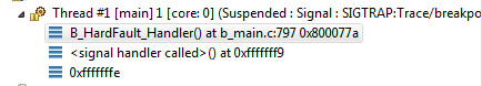
Ozone generates a number of callbacks in its project file, when the project is first saved. Among others, there is the code to load PC and SP:
void TargetReset (void) {

  unsigned int SP;
  unsigned int PC;
  unsigned int VectorTableAddr;

  VectorTableAddr = Elf.GetBaseAddr();

  // Set up initial stack pointer

  if (VectorTableAddr != 0xFFFFFFFF) {
    SP = Target.ReadU32(VectorTableAddr);
    Target.SetReg("SP", SP);
  }

  // Set up entry point PC

  PC = Elf.GetEntryPointPC();

  if (PC != 0xFFFFFFFF) {
    Target.SetReg("PC", PC);
  } else if (VectorTableAddr != 0xFFFFFFFF) {
    PC = Target.ReadU32(VectorTableAddr + 4);
    Target.SetReg("PC", PC);
  } else {
    Util.Error("Project file error: failed to set entry point PC", 1);
  }
}
It gets SP from the vector table. Then it tries to get PC from the ELF entry point, and if not available, gets it from the vector table as well. Other debuggers might do things differently.
You would probably want to add this information into "Advanced" section
-
#13 Reply
Posted by
peter-h
on 28 Sep, 2022 10:46
-
It is an interesting debate whether for a "bare metal tutorial" one should recommend
- what is basically a batchfile to compile and link, and the use of the Ozone debugger (which, unless you pay, keeps popping up the licensing message, IME), or
- a simple Cube IDE setup, and STLINK (which is far cheaper than anything from Segger)
I am currently writing the RM for a product which will have a user programmable portion so I am addressing these same issues. Cube was chosen because it is totally free, works as well as any other "mfg tool", and if you give somebody a trivial "hello world" project to import, it all works out of the box. Just press F11 and it all happens right. And if you split up your project to multiple files (which is certain for anything nontrivial, and for trivia link flashing an LED you won't be using a 32F4!) you don't have to edit a batchfile or a makefile etc.
For many years I have been selling an H8/300 based product, also user programmable, where the compiler was sold for £450. It was OK in the past (hundreds of compilers were sold, mainly to large companies) but today this is not acceptable. People are used to paying far less to get started.
This is getting well away from the original idea but the feeling I get is that people struggle not in getting an LED to blink (might waste a few days of your life on that) but with integrating the kind of stuff which a typical 32F4+ project is used for: ETH, LWIP, FreeRTOS, USB. That is what STM have done relatively badly and Espressif have done well (allegedly they recruited some "know it all" from the forums). In the ST world you could easily spend a year of your life debugging it, and since most of it is severely real time (e.g. can't really step through USB code because the other end dies) you spend much of that time googling for forum posts and trying different things.
-
#14 Reply
Posted by
tellurium
on 28 Sep, 2022 16:22
-
Maybe a thick line saying "this is it, what follows is advanced topics" would do the trick?
That's a good question.
I guess yes, for those who need it, an advanced-bare-metal-programming-guide can be created, which can cover a lot more.
How to do things so that they won't fall into TLDR cathegory? A tutorial maybe shouldn't take more to read than is time to install an IDE?
Not sure. Installing an IDE does not give an understanding. Reading a tutorial, and repeating its steps, does. So I would not compare them in terms of time.
-
#15 Reply
Posted by
wek
on 28 Sep, 2022 17:03
-
How to do things so that they won't fall into TLDR cathegory? A tutorial maybe shouldn't take more to read than is time to install an IDE?
Not sure. Installing an IDE does not give an understanding. Reading a tutorial, and repeating its steps, does. So I would not compare them in terms of time.
I absolutely see your point, however, I'm not your target audience. A novice does not crave understanding, but quick results.
JW
-
#16 Reply
Posted by
peter-h
on 28 Sep, 2022 17:32
-
The bigger issue is that applications using these chips are
complex.
After you've got past flashing an LED, you are into a whole world of hassle, steep learning curves, googling thousands of forum posts, trying thousands of things to see what works, steep learning curves all the way. My life for last 2 years, actually...
My current project has 63 .c files and that is just "my" stuff. Then there are 3227 other .c files in the various 3rd party libs. You would go totally mad just maintaining a makefile for that lot.
Setting up say Cube IDE is about 1% of the learning curve involved in producing a
reliably working target with ETH, LWIP, USB, FreeRTOS, maybe - for true masochists - even MbedTLS...
Then add the fees of a psychiatrist who you will need to visit for regular counselling of your inferiority complex after getting "help" from a certain guy on the ST forum who wastes no time in telling you that you are a complete moron
Even by the standards of internet behaviour (which I am ok with; I even run a "technology" forum myself, so my skin is thick enough) this was a novel experience.
-
#17 Reply
Posted by
tellurium
on 28 Sep, 2022 18:13
-
These are valid points, Peter.
When there is an understanding of different approaches, one can make an informed decision.
My goal was to show that a bare metal approach is easy. Well, easier than one may think.
-
#18 Reply
Posted by
peter-h
on 28 Sep, 2022 19:31
-
I agree, and I think you need to add the clock (PLL) setup like I posted. Everybody will need that, and I don't think it differs much between applications.
When I think back, that stuff was basically undocumented and was worked out only by examining the various disjointed stubs generated by MX. But it is critical code.
-
#19 Reply
Posted by
betocool
on 29 Sep, 2022 10:58
-
I liked the tutorial, thanks for the effort! That being said, I'm not the target audience but I would have been when I began doing micro stuff with STM32 over 10 years ago.
I followed the instructions of a Swedish guy somewhere online for the Linux installation and it was a MASSIVE PAIN! But I got my STM32F103 up and running, and put it in a guitar amp as simple DSP after a while.
Then I tried Codeblocks, Make, GCC and GDB, and they worked a bit better. Still a pain to get all the init stuff from STM32 but it worked.
Then came SystemWorkbench, which was a great improvement in my opinion because it brought together an IDE and compiler for STM32, and later could import STM32 Cube projects, which where awesome for laying the ground work on your micro.
Now we have STM32CubeIDE and CUBEMX in one box. Do I like it? Yes I do, I feel I've gone through the necessary steps of understanding to finally have a one-button-click solution to get a project up and running in minutes, even on a new micro.
All of the above being said, I'm still curious about the CubeMX makefile generation option, and getting that using VS Code, which I really like as an IDE / Editor, whatever you want to call it.
Sorry, off topic a bit, bottom line, I think the tutorial is great, and if someone's a bit tech-savvy it's very good to get someone started, certainly better than what it was a decade ago.
Cheers,
Alberto
-
#20 Reply
Posted by
tellurium
on 30 Nov, 2022 19:12
-
-
#21 Reply
Posted by
wek
on 04 Dec, 2022 01:30
-
It's an impressive work. Thanks.
I hate myself for criticizing it since I did not contribute a iota, but can you please make it clear that the setup is linux(*)-centric? The reason for this is, that to the everyday windows user in 2022 it's not as simple as "install gcc and suite, install make, install stlink, and you're done". And adding "start with installing msys2 or a VM with linux" won't make it much easier.
(*)-okay, unix, but to the everyday windows user in 2022 would make it probably even more confusing.
JW
-
#22 Reply
Posted by
tellurium
on 04 Dec, 2022 11:27
-
Ah, yes, that makes sense.
The whole tutorial was implemented on Mac actually; I assume it works the same on Linux.
I need to add a "tool setup" section for Windows users (which, I think, is a majority).
-
#23 Reply
Posted by
tellurium
on 04 Dec, 2022 22:10
-
Added quick reference to the very beginning for the tools setup on Mac, Linux, Windows.
I think an explainer video that goes through the whole tutorial might be helpful, too - maybe that will be added later, too.
-
#24 Reply
Posted by
wek
on 04 Dec, 2022 23:24
-
Nice.
Now what about this one?
c:\wek\tmp\tmp\bare-metal-programming-guide-main\step-0-minimal>make
arm-none-eabi-gcc main.c  -W -Wall -Wextra -Werror -Wundef -Wshadow -Wdouble-promotion -Wformat-truncation -fno-common -Wconversion -g3
-Os -ffunction-sections -fdata-sections -I. -mcpu=cortex-m4 -mthumb -mfloat-abi=hard -mfpu=fpv4-sp-d16 -Tlink.ld -nostartfiles -nostdlib
--specs nano.specs -lc -lgcc -Wl,--gc-sections -Wl,-Map=firmware.elf.map -o firmware.elf

c:\wek\tmp\tmp\bare-metal-programming-guide-main\step-0-minimal>make clean
rm -rf firmware.*
process_begin: CreateProcess(NULL, rm -rf firmware.*, ...) failed.
make (e=2): The system cannot find the file specified.
make: *** [Makefile:20: clean] Error 2

c:\wek\tmp\tmp\bare-metal-programming-guide-main\step-0-minimal>
I personally like to use WinAVR for this purpose, it contains a collection of unix-like-"standard" tools, but is somewhat... old... and its primary purpose is different.
JW