Author Topic: RS-485 Synchronous Mode ( CLK + DATA )  (Read 5711 times)

0 Members and 1 Guest are viewing this topic.

Offline Siwastaja

  • Super Contributor
  • ***
  • Posts: 8173
  • Country: fi
Re: RS-485 Synchronous Mode ( CLK + DATA )
« Reply #25 on: July 31, 2023, 09:35:54 am »
RS485 would usually drive eg +4.8v for 1, drive -4.8v for 0

No, definitely not. The numbers as posted seem about right for an unterminated bus.

EDIT: Or you mean as measured between A and B? That would be correct then.
« Last Edit: July 31, 2023, 09:40:19 am by Siwastaja »
 

Offline mikeselectricstuff

  • Super Contributor
  • ***
  • Posts: 13748
  • Country: gb
    • Mike's Electric Stuff
Re: RS-485 Synchronous Mode ( CLK + DATA )
« Reply #26 on: July 31, 2023, 10:16:59 am »
Because "RS485 synchronous mode" is not a thing, what are you actually doing? What device(s) are you communicating with? Single unidirectional link, bidirectional link, multi-slave bus? Maybe you mean synchronous serial data over RS422 with two differential lanes, one for data one for clock?

I've used RS485 with the direction hardcoded and always-on. I didn't realize it was called RS422!

I've seen insane issues with RS485 failures in the field specifically due to the idle noise jamming the whole thing. It was enough to bring most of an entire EVSE site down due to a really bad design (under-terminated, no "fail-safe" biasing, and direct Y-cap between Neutral and RS485 reference line). It's a horrible bus, and I wouldn't use it unless it was the RS422 version.
A problem with RS485 is it can be too robust, so with issues like bad termination, open cores or shorts to ground, it can still appear to work fine, and only show issues when wiring is changed, other devices are connected, there is no common ground, phase of the moon changes etc.
This is why it is extremely important to test cabling when instralling, not just assume it's OK if the system appears to work.
Youtube channel:Taking wierd stuff apart. Very apart.
Mike's Electric Stuff: High voltage, vintage electronics etc.
Day Job: Mostly LEDs
 
The following users thanked this post: tooki, pacioc193

Online DiTBho

  • Super Contributor
  • ***
  • Posts: 3915
  • Country: gb
Re: RS-485 Synchronous Mode ( CLK + DATA )
« Reply #27 on: July 31, 2023, 10:54:29 am »
So, again: why not CanBus  :D?
The opposite of courage is not cowardice, it is conformity. Even a dead fish can go with the flow
 

Offline PCB.Wiz

  • Super Contributor
  • ***
  • Posts: 1545
  • Country: au
Re: RS-485 Synchronous Mode ( CLK + DATA )
« Reply #28 on: July 31, 2023, 11:08:09 am »
So, again: why not CanBus  :D?
I think the op has to retro fit existing equipment, meaning they do not have full control over both end’s hardware.
 
The following users thanked this post: Siwastaja, pacioc193

Offline pacioc193Topic starter

  • Regular Contributor
  • *
  • Posts: 57
  • Country: it
Re: RS-485 Synchronous Mode ( CLK + DATA )
« Reply #29 on: July 31, 2023, 03:13:21 pm »
As already explain i can't choose a communication protocol. This is already choosen HDLC over RS-485.
Have you got some schematic to share on how create a stable communication over 485 without any ground shared beetween the two system with voltage 0-5V?
No negative voltage are present on the rail. I know that original RS-485 use +/-24VDC to be more stable.

The old PCI board is the following : MCXCPCI-570-WAN-HDLC

They have connect together 
pin   2 TxD Transmit Data Output (A)
pin   3 RxD Receive Data Input (A)

pin 14 TxD Transmit Data Output (B)
pin 16 RxD Receive Data Input (B)

And

pin   9 RxClkIn Receive Clock Input (B)
pin 11 TxClkOut Transmit Clock Output (B)

pin 24 TxClkOut Transmit Clock Output (A)
pin 17 RxClkIn Receive Clock Input (A)

The board is programmed to works as Synchronous HDLC/SDLC/BISYNC.

As already written i've already implemented the HDLC as bit/bang protocol. I need just a stable transceiver to make a good communication over HDLC

« Last Edit: July 31, 2023, 03:22:12 pm by pacioc193 »
 

Offline pacioc193Topic starter

  • Regular Contributor
  • *
  • Posts: 57
  • Country: it
Re: RS-485 Synchronous Mode ( CLK + DATA )
« Reply #30 on: July 31, 2023, 03:26:52 pm »
You are correct... i'm not able to determinate a working situation that is stable for more than 1 days. I went to launch and the communication was completely off.
I've a working microcontroller software but not a working communication hardware...
 

Offline Siwastaja

  • Super Contributor
  • ***
  • Posts: 8173
  • Country: fi
Re: RS-485 Synchronous Mode ( CLK + DATA )
« Reply #31 on: July 31, 2023, 03:27:56 pm »
Have you got some schematic to share on how create a stable communication over 485 without any ground shared beetween the two system with voltage 0-5V?

One more question would be needed, that would be the level of isolation; functional, basic or reinforced? In any case, I'd recommend looking at integrated isolated RS485 transceiver ICs, e.g. https://www.ti.com/isolation/isolated-interfaces/rs-485-transceivers/products.html , see what you can get from your component distributor and implement their datasheet example.

Quote
I know that original RS-485 use +/-24VDC to be more stable.
That would not be RS485, then, but something else mislabeled.
 

Offline pacioc193Topic starter

  • Regular Contributor
  • *
  • Posts: 57
  • Country: it
Re: RS-485 Synchronous Mode ( CLK + DATA )
« Reply #32 on: July 31, 2023, 03:53:03 pm »
Have you got some schematic to share on how create a stable communication over 485 without any ground shared beetween the two system with voltage 0-5V?

One more question would be needed, that would be the level of isolation; functional, basic or reinforced? In any case, I'd recommend looking at integrated isolated RS485 transceiver ICs, e.g. https://www.ti.com/isolation/isolated-interfaces/rs-485-transceivers/products.html , see what you can get from your component distributor and implement their datasheet example.

Quote
I know that original RS-485 use +/-24VDC to be more stable.
That would not be RS485, then, but something else mislabeled.

The level of isolation is not requested... right now we are working on a bench. No high voltage present. Wire lenght 1m.
Classic MAX485 will not work?
« Last Edit: July 31, 2023, 03:54:46 pm by pacioc193 »
 

Offline peter-h

  • Super Contributor
  • ***
  • Posts: 3698
  • Country: gb
  • Doing electronics since the 1960s...
Re: RS-485 Synchronous Mode ( CLK + DATA )
« Reply #33 on: July 31, 2023, 04:15:03 pm »
Quote
I've used RS485 with the direction hardcoded and always-on. I didn't realize it was called RS422!

Well, the Master on a 4-wire RS485 bus is effectively an RS422 device, because its TX drives only receivers, so never needs to tri-state :)

Modbus over HDLC - this breaks new ground!

I know Bisync - was used since 1980s, mostly by Eurotherm, for their process controllers. I once did a converter between Bisync and Modbus. Strictly for masochists :)

A google on MCXCPCI-570-WAN-HDLC turns up some fun stuff
https://www.acksys.fr/en/product/48-wan-hdlc-range/


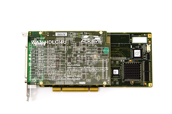
It looks very similar to another French outfit - MAX Technologies - which clearly made its money selling ATE systems to Airbus and to French military. I have some MAX cards (PCMCIA and PCI, ARINC429). These work on the French principle (OK in practice but will never work in theory, so, Serge, this will never work, we need more complexity). MAX are still there, still supporting their old stuff.

https://www.acksys.fr/wp-content/uploads/products/MCXCPCI-570-WAN-HDLC-Hardware-FR_only-DT063.pdf

These cards were done as a tour de force project in digital design. Full of huge FPGAs, and big CPU chips from the 1990s.

Reverse engineering this, even in a narrow bit of functionality, is going to be hard work. For a start, any Modbus-other converter has to deal with register mapping. There is no standard for this. Then HDLC is a big can of worms. It is basically meaningless outside of a specific (originally IBM) context, and here somebody has "bent it" to do something else.

I've done this kind of work ~30 years ago, with FPGAs, but this job is 10x more horrible.

These cards sometimes come up on Ebay.

I suspect whoever specced this project has no idea of the engineering required. It's like, many years ago, the Intel 186 was scarce, and a colleague was tasked with emulating it with 74LS logic.
Z80 Z180 Z280 Z8 S8 8031 8051 H8/300 H8/500 80x86 90S1200 32F417
 

Offline pacioc193Topic starter

  • Regular Contributor
  • *
  • Posts: 57
  • Country: it
Re: RS-485 Synchronous Mode ( CLK + DATA )
« Reply #34 on: July 31, 2023, 04:23:07 pm »
My intention is not to reconstruct the entire board, but only the part necessary for communication with my CPU. The only thing left for me to do is to properly command a transcoder from bit/bang to RS-485.
 

Offline Siwastaja

  • Super Contributor
  • ***
  • Posts: 8173
  • Country: fi
Re: RS-485 Synchronous Mode ( CLK + DATA )
« Reply #35 on: July 31, 2023, 06:58:37 pm »
The level of isolation is not requested... right now we are working on a bench. No high voltage present. Wire lenght 1m.
Classic MAX485 will not work?

To me it sounds like you don't have any real reason for isolation. Frankly, I would use any RS485 transceiver (e.g. MAX485) and add the GND wire which is currently missing between the two systems. It's a very very common misunderstanding that RS485 does not need this wire so even some professionally engineered products fail to have it. Sometimes they still work because of unexpected grounding routes (e.g. through protective earth of building) or parasitics.

Maybe the original products did not have isolation either and therefore did actually kinda pull their grounds together via the RS485 data lines via overvoltage protection (of the transceivers).

But of course not knowing enough about the exact details I can't guarantee this works. Maybe the original thing did have isolation and maybe you need it. I'm just guessing this is not the case.
 
The following users thanked this post: pacioc193

Offline PCB.Wiz

  • Super Contributor
  • ***
  • Posts: 1545
  • Country: au
Re: RS-485 Synchronous Mode ( CLK + DATA )
« Reply #36 on: July 31, 2023, 07:03:36 pm »
Quote
No negative voltage are present on the rail.
It signals across A-B, So a differential bus has positive and negative driven states.
Floating may need some bus biasing to give a stable margin value.

GND connection is inferred, there is a modest common mode tolerance designed to tolerate GND shifts, but fully isolated will not work.


Quote
i'm not able to determinate a working situation that is stable for more than 1 days. I went to launch and the communication was completely off.
I've a working microcontroller software but not a working communication hardware...
Lunch ?
The links I posted include scope shots. How do yours compare ?

‘Stable for even 1 day, is very different from not working hardware.
How many packets pass / fail here ?
 
The following users thanked this post: pacioc193

Offline pacioc193Topic starter

  • Regular Contributor
  • *
  • Posts: 57
  • Country: it
Re: RS-485 Synchronous Mode ( CLK + DATA )
« Reply #37 on: July 31, 2023, 07:12:56 pm »
The level of isolation is not requested... right now we are working on a bench. No high voltage present. Wire lenght 1m.
Classic MAX485 will not work?

To me it sounds like you don't have any real reason for isolation. Frankly, I would use any RS485 transceiver (e.g. MAX485) and add the GND wire which is currently missing between the two systems. It's a very very common misunderstanding that RS485 does not need this wire so even some professionally engineered products fail to have it. Sometimes they still work because of unexpected grounding routes (e.g. through protective earth of building) or parasitics.

Maybe the original products did not have isolation either and therefore did actually kinda pull their grounds together via the RS485 data lines via overvoltage protection (of the transceivers).

But of course not knowing enough about the exact details I can't guarantee this works. Maybe the original thing did have isolation and maybe you need it. I'm just guessing this is not the case.

What i cannot understand is the affermation : RS-485 doesn't need the GND common between all the nodes in the communication bus. This affermation is not true then? Ground must be present and if you don't wan't to share ground you must use some optoisolated transceiver?
I don't have exact detail unlike... just a big challenge for me.
There is not a breakout board for optoisolated rs-485 transceiver to give a shot?


Offline pacioc193Topic starter

  • Regular Contributor
  • *
  • Posts: 57
  • Country: it
Re: RS-485 Synchronous Mode ( CLK + DATA )
« Reply #38 on: July 31, 2023, 07:19:02 pm »
Quote
No negative voltage are present on the rail.
It signals across A-B, So a differential bus has positive and negative driven states.
Floating may need some bus biasing to give a stable margin value.

GND connection is inferred, there is a modest common mode tolerance designed to tolerate GND shifts, but fully isolated will not work.


Quote
i'm not able to determinate a working situation that is stable for more than 1 days. I went to launch and the communication was completely off.
I've a working microcontroller software but not a working communication hardware...
Lunch ?
The links I posted include scope shots. How do yours compare ?

‘Stable for even 1 day, is very different from not working hardware.
How many packets pass / fail here ?


The systems are complete isolated. I'm pretty sure about that because the target has his own power supply and the computer to the destination CPU has just 4 wires : Data(A) Data(B) CLK(A) CLK(B).
I cannot compare with the links that you posted to me.
I replicate the RS-485 communication using bit/bang algorithm generating all the data from the ESP8266, merging ground and the system working very well even without transceiver...
Unluky this is not the definite board. I need the RS485 communication working without a ground cable.

I will try to post some packet analyzing but i don't have with me the one during issue using RS485 transceiver.
 

Online nctnico

  • Super Contributor
  • ***
  • Posts: 26907
  • Country: nl
    • NCT Developments
Re: RS-485 Synchronous Mode ( CLK + DATA )
« Reply #39 on: July 31, 2023, 07:20:27 pm »
The level of isolation is not requested... right now we are working on a bench. No high voltage present. Wire lenght 1m.
Classic MAX485 will not work?

To me it sounds like you don't have any real reason for isolation. Frankly, I would use any RS485 transceiver (e.g. MAX485) and add the GND wire which is currently missing between the two systems. It's a very very common misunderstanding that RS485 does not need this wire so even some professionally engineered products fail to have it. Sometimes they still work because of unexpected grounding routes (e.g. through protective earth of building) or parasitics.

Maybe the original products did not have isolation either and therefore did actually kinda pull their grounds together via the RS485 data lines via overvoltage protection (of the transceivers).

But of course not knowing enough about the exact details I can't guarantee this works. Maybe the original thing did have isolation and maybe you need it. I'm just guessing this is not the case.

What i cannot understand is the affermation : RS-485 doesn't need the GND common between all the nodes in the communication bus. This affermation is not true then? Ground must be present and if you don't wan't to share ground you must use some optoisolated transceiver?
I don't have exact detail unlike... just a big challenge for me.
There is not a breakout board for optoisolated rs-485 transceiver to give a shot?
RS485 needs a ground reference although some offset (depending on the transceiver is allowed). If you have reason to believe there will be more offset than you transceivers can tolerate, then you'll need an isolated setup. There are complete chips (not cheap) from TI and/or Analog devices that will create an isolated RS485 bridge between two systems.

All in all I suggest you make more measurements and do more research into how the original systems are physically connected where it comes to grounding. AND reverse engineer their driver circuitry to get a full understanding on how the interfaces need to be setup electrically.
 
There are small lies, big lies and then there is what is on the screen of your oscilloscope.
 
The following users thanked this post: Siwastaja, pacioc193

Offline pacioc193Topic starter

  • Regular Contributor
  • *
  • Posts: 57
  • Country: it
Re: RS-485 Synchronous Mode ( CLK + DATA )
« Reply #40 on: July 31, 2023, 07:33:13 pm »
Just to give some idea.

In this capture are present my request and the answer from the CPU.

I bit/bang the Data(A) Data(B) and CLK(A) CLK(B) using the ESP8266 with common GND


This is my TX packet


Using without GND shared, also using commond MAX485, packet analyzer show something like this ( i recreate it manually because i didn't get any image on last try )


Where all 0 were replaced by some voltage ( with oscilloscope i seen that a big jittering appear on the signal ). This happen only if i connet my ESP88266 ( with transceiver or without ) to the slave CPU.

I'm not sure about ground issue but this is my only idea....
« Last Edit: July 31, 2023, 07:35:21 pm by pacioc193 »
 

Offline pacioc193Topic starter

  • Regular Contributor
  • *
  • Posts: 57
  • Country: it
Re: RS-485 Synchronous Mode ( CLK + DATA )
« Reply #41 on: July 31, 2023, 07:48:33 pm »
The level of isolation is not requested... right now we are working on a bench. No high voltage present. Wire lenght 1m.
Classic MAX485 will not work?

To me it sounds like you don't have any real reason for isolation. Frankly, I would use any RS485 transceiver (e.g. MAX485) and add the GND wire which is currently missing between the two systems. It's a very very common misunderstanding that RS485 does not need this wire so even some professionally engineered products fail to have it. Sometimes they still work because of unexpected grounding routes (e.g. through protective earth of building) or parasitics.

Maybe the original products did not have isolation either and therefore did actually kinda pull their grounds together via the RS485 data lines via overvoltage protection (of the transceivers).

But of course not knowing enough about the exact details I can't guarantee this works. Maybe the original thing did have isolation and maybe you need it. I'm just guessing this is not the case.

What i cannot understand is the affermation : RS-485 doesn't need the GND common between all the nodes in the communication bus. This affermation is not true then? Ground must be present and if you don't wan't to share ground you must use some optoisolated transceiver?
I don't have exact detail unlike... just a big challenge for me.
There is not a breakout board for optoisolated rs-485 transceiver to give a shot?
RS485 needs a ground reference although some offset (depending on the transceiver is allowed). If you have reason to believe there will be more offset than you transceivers can tolerate, then you'll need an isolated setup. There are complete chips (not cheap) from TI and/or Analog devices that will create an isolated RS485 bridge between two systems.

All in all I suggest you make more measurements and do more research into how the original systems are physically connected where it comes to grounding. AND reverse engineer their driver circuitry to get a full understanding on how the interfaces need to be setup electrically.
 

There is not possibility to communicate with another system without using any kind of ground?
Watching the classic MAX485 tranceiver is not showing anywhere that the system must share ground


This is a my big mental limitation...
 

Offline PCB.Wiz

  • Super Contributor
  • ***
  • Posts: 1545
  • Country: au
Re: RS-485 Synchronous Mode ( CLK + DATA )
« Reply #42 on: July 31, 2023, 08:11:49 pm »
Quote
The systems are complete isolated. I'm pretty sure about that because the target has his own power supply and the computer to the destination CPU has just 4 wires : Data(A) Data(B) CLK(A) CLK(B)
The mains supply surely has a ground ?
Just run a Gnd cable and test it.

Quote
There is not possibility to communicate with another system without using any kind of ground?
Watching the classic MAX485 transceiver is not showing anywhere that the system must share ground
Classic MAX485 has common mode voltage limits, it is not fully isolated

Yes, google ISOLATED RS485
That has usually opto couplers and switching isolated power supplies added to ‘vanilla’ rs485
 

Online nctnico

  • Super Contributor
  • ***
  • Posts: 26907
  • Country: nl
    • NCT Developments
Re: RS-485 Synchronous Mode ( CLK + DATA )
« Reply #43 on: July 31, 2023, 08:17:23 pm »
The level of isolation is not requested... right now we are working on a bench. No high voltage present. Wire lenght 1m.
Classic MAX485 will not work?

To me it sounds like you don't have any real reason for isolation. Frankly, I would use any RS485 transceiver (e.g. MAX485) and add the GND wire which is currently missing between the two systems. It's a very very common misunderstanding that RS485 does not need this wire so even some professionally engineered products fail to have it. Sometimes they still work because of unexpected grounding routes (e.g. through protective earth of building) or parasitics.

Maybe the original products did not have isolation either and therefore did actually kinda pull their grounds together via the RS485 data lines via overvoltage protection (of the transceivers).

But of course not knowing enough about the exact details I can't guarantee this works. Maybe the original thing did have isolation and maybe you need it. I'm just guessing this is not the case.

What i cannot understand is the affermation : RS-485 doesn't need the GND common between all the nodes in the communication bus. This affermation is not true then? Ground must be present and if you don't wan't to share ground you must use some optoisolated transceiver?
I don't have exact detail unlike... just a big challenge for me.
There is not a breakout board for optoisolated rs-485 transceiver to give a shot?
RS485 needs a ground reference although some offset (depending on the transceiver is allowed). If you have reason to believe there will be more offset than you transceivers can tolerate, then you'll need an isolated setup. There are complete chips (not cheap) from TI and/or Analog devices that will create an isolated RS485 bridge between two systems.

All in all I suggest you make more measurements and do more research into how the original systems are physically connected where it comes to grounding. AND reverse engineer their driver circuitry to get a full understanding on how the interfaces need to be setup electrically.
 

There is not possibility to communicate with another system without using any kind of ground?
Watching the classic MAX485 tranceiver is not showing anywhere that the system must share ground


This is a my big mental limitation...
The clue is in the absolute maximum voltage ratings for the receiver (A/ B) pins and the current limits at the extremes of the common mode voltage.
There are small lies, big lies and then there is what is on the screen of your oscilloscope.
 

Offline pacioc193Topic starter

  • Regular Contributor
  • *
  • Posts: 57
  • Country: it
Re: RS-485 Synchronous Mode ( CLK + DATA )
« Reply #44 on: July 31, 2023, 08:27:08 pm »
Quote
The systems are complete isolated. I'm pretty sure about that because the target has his own power supply and the computer to the destination CPU has just 4 wires : Data(A) Data(B) CLK(A) CLK(B)
The mains supply surely has a ground ?
Just run a Gnd cable and test it.

Quote
There is not possibility to communicate with another system without using any kind of ground?
Watching the classic MAX485 transceiver is not showing anywhere that the system must share ground
Classic MAX485 has common mode voltage limits, it is not fully isolated

Yes, google ISOLATED RS485
That has usually opto couplers and switching isolated power supplies added to ‘vanilla’ rs485

Something like this could be used to test if the solution is to use isolated?

https://wiki.dfrobot.com/Gravity_Active_Isolated_RS485_to_UART_Signal_Converter_SKU_DFR0845

Or better

https://digilent.com/reference/pmod/pmodrs485/reference-manual
« Last Edit: July 31, 2023, 08:38:55 pm by pacioc193 »
 

Offline PCB.Wiz

  • Super Contributor
  • ***
  • Posts: 1545
  • Country: au
Re: RS-485 Synchronous Mode ( CLK + DATA )
« Reply #45 on: July 31, 2023, 09:07:14 pm »

Something like this could be used to test if the solution is to use isolated?

https://wiki.dfrobot.com/Gravity_Active_Isolated_RS485_to_UART_Signal_Converter_SKU_DFR0845

Or better

https://digilent.com/reference/pmod/pmodrs485/reference-manual

Yes, the 'or better' is much better. I was about to find an example.

That has optional DE,REN lines, that control the directions and drivers, the simpler kludge ones hide that internally, and you already do SW control, so you can add DE_REN drive.

Addit: it also has separate TX/RX, as in RS422, which is what you actually want - note your host has separate pins, so just wire to those, and simplify DE_REN. (always on)

The old PCI board is the following : MCXCPCI-570-WAN-HDLC

pin   2 TxD Transmit Data Output (A)    pin 14 TxD Transmit Data Output (B)
pin 11 TxClkOut Transmit Clock Output (B)   pin 24 TxClkOut Transmit Clock Output (A)

pin   3 RxD Receive Data Input (A)   pin 16 RxD Receive Data Input (B)
pin   9 RxClkIn Receive Clock Input (B) pin 17 RxClkIn Receive Clock Input (A)


Your SW side always listens to the remote TXD lines and drives the remote RXD lines.
« Last Edit: July 31, 2023, 09:31:39 pm by PCB.Wiz »
 

Offline PCB.Wiz

  • Super Contributor
  • ***
  • Posts: 1545
  • Country: au
Re: RS-485 Synchronous Mode ( CLK + DATA )
« Reply #46 on: July 31, 2023, 09:14:08 pm »
Just to give some idea.

In this capture are present my request and the answer from the CPU.

I bit/bang the Data(A) Data(B) and CLK(A) CLK(B) using the ESP8266 with common GND
These seem to show some quasi differential signal, as they idle at the same voltage (wrong for differential). ?
Are you driving all 4 lines in software ? Normal would be to generate Data and CLK and use the transceiver hardware to do the differential drive.
 

Offline pacioc193Topic starter

  • Regular Contributor
  • *
  • Posts: 57
  • Country: it
Re: RS-485 Synchronous Mode ( CLK + DATA )
« Reply #47 on: July 31, 2023, 09:23:26 pm »
Just to give some idea.

In this capture are present my request and the answer from the CPU.

I bit/bang the Data(A) Data(B) and CLK(A) CLK(B) using the ESP8266 with common GND
These seem to show some quasi differential signal, as they idle at the same voltage (wrong for differential). ?
Are you driving all 4 lines in software ? Normal would be to generate Data and CLK and use the transceiver hardware to do the differential drive.

Yes I generate all 4 lines in software via bit/bang algo and I confirm that the CPU is accepting also this kind of signal.
I know is not a pure rs485 signal but from my limitate knowledge I was thinking that gnd could not be used with transceiver.
Could be possible that a not connected gnd lines generate that jittering on the AB channel of the rs485 lines?

 I will give a try with this opto isolated transceiver and give a feedback. Thanks for all the patience.
 

Offline PCB.Wiz

  • Super Contributor
  • ***
  • Posts: 1545
  • Country: au
Re: RS-485 Synchronous Mode ( CLK + DATA )
« Reply #48 on: July 31, 2023, 09:49:26 pm »
Yes I generate all 4 lines in software via bit/bang algo and I confirm that the CPU is accepting also this kind of signal.
I know is not a pure rs485 signal but from my limitate knowledge I was thinking that gnd could not be used with transceiver.

The basic idea is good, and is a way to get some echo out of the remote unit, as a sign-of-life test. It sounds like you do have echoes ?
I would clean up the SW idle states so they are truly differential ( B lines = !A lines  always)

that will work to test these lines
pin   3 RxD Receive Data Input (A)   pin 16 RxD Receive Data Input (B)
pin   9 RxClkIn Receive Clock Input (B) pin 17 RxClkIn Receive Clock Input (A)


 you cannot just wire your MCU to the other direction wires, but you can scope them and confirm a packet replies as expected.

to test
pin   2 TxD Transmit Data Output (A)    pin 14 TxD Transmit Data Output (B)
pin 11 TxClkOut Transmit Clock Output (B)   pin 24 TxClkOut Transmit Clock Output (A)

to your MCU, you need 2 x differential receivers.
An H11L1 optocoupler might be pressed into quick bench test use, so you can sample the echo as CMOS levels.
The digilent RS485/RS422 is a proper solution,  but you may want to test something while waiting for that to arrive  8)

Addit: another alternative, non-isolated?**  RS422 equivalent  - gives TTL to DIFF x2, order time choice of 3.3V / 5V
https://www.aliexpress.com/item/1005004149339932.html
better images
https://www.aliexpress.com/item/1005004933919596.html

** I think that is isolated, the ADUM3201ARZ is a one each way isolator and the black block, looks like a small DC-DC
« Last Edit: August 01, 2023, 03:03:58 am by PCB.Wiz »
 

Offline pacioc193Topic starter

  • Regular Contributor
  • *
  • Posts: 57
  • Country: it
Re: RS-485 Synchronous Mode ( CLK + DATA )
« Reply #49 on: August 01, 2023, 06:50:40 am »
Yes I generate all 4 lines in software via bit/bang algo and I confirm that the CPU is accepting also this kind of signal.
I know is not a pure rs485 signal but from my limitate knowledge I was thinking that gnd could not be used with transceiver.

The basic idea is good, and is a way to get some echo out of the remote unit, as a sign-of-life test. It sounds like you do have echoes ?
I would clean up the SW idle states so they are truly differential ( B lines = !A lines  always)

that will work to test these lines
pin   3 RxD Receive Data Input (A)   pin 16 RxD Receive Data Input (B)
pin   9 RxClkIn Receive Clock Input (B) pin 17 RxClkIn Receive Clock Input (A)


 you cannot just wire your MCU to the other direction wires, but you can scope them and confirm a packet replies as expected.

to test
pin   2 TxD Transmit Data Output (A)    pin 14 TxD Transmit Data Output (B)
pin 11 TxClkOut Transmit Clock Output (B)   pin 24 TxClkOut Transmit Clock Output (A)

to your MCU, you need 2 x differential receivers.
An H11L1 optocoupler might be pressed into quick bench test use, so you can sample the echo as CMOS levels.
The digilent RS485/RS422 is a proper solution,  but you may want to test something while waiting for that to arrive  8)

Addit: another alternative, non-isolated?**  RS422 equivalent  - gives TTL to DIFF x2, order time choice of 3.3V / 5V
https://www.aliexpress.com/item/1005004149339932.html
better images
https://www.aliexpress.com/item/1005004933919596.html

** I think that is isolated, the ADUM3201ARZ is a one each way isolator and the black block, looks like a small DC-DC

Thanks so much for all this kindly information.
Yes opencollector optoisolator could be a good idea for check if the CPU answer.
I've found on digikey the digilent breakout board, couple of day and i will continue my research.

I don't want to take something on aliexpress that is not sure about the real working principle.

Thanks !
 
The following users thanked this post: PCB.Wiz


Share me

Digg  Facebook  SlashDot  Delicious  Technorati  Twitter  Google  Yahoo
Smf