Author Topic: RS-485 Synchronous Mode ( CLK + DATA )  (Read 5735 times)

0 Members and 1 Guest are viewing this topic.

Offline pacioc193Topic starter

  • Regular Contributor
  • *
  • Posts: 57
  • Country: it
RS-485 Synchronous Mode ( CLK + DATA )
« on: July 28, 2023, 07:17:07 pm »
Anyone has experience on a good transceiver that is able to generate clock when a TX happen?
I need to create a board that is able to communicate in RS485 5V in synchronous mode with all signal D+ D- CLK+ CLK- as HDLC Synchronous board.
I've done a sketch with ESP8266 and seems works but the issue is related to the fact that RS485 stay always in high state when not transmission happen using this protoboard attached.
Anyone has some suggestion?
« Last Edit: July 28, 2023, 07:30:36 pm by pacioc193 »
 

Offline Doctorandus_P

  • Super Contributor
  • ***
  • Posts: 3367
  • Country: nl
Re: RS-485 Synchronous Mode ( CLK + DATA )
« Reply #1 on: July 29, 2023, 11:12:41 am »
Something like
RS485 5V in synchronous mode

does not really exist.

Quote from: https://en.wikipedia.org/wiki/RS-485
Protocols
RS-485 does not define a communication protocol; merely an electrical interface. Although many applications use RS-485 signal levels, the speed, format, and protocol of the data transmission are not specified by RS-485. Interoperability of even similar devices from different manufacturers is not assured by compliance with the signal levels alone.

RS485 can be (ab) used for all kinds of (usually serial) data. But as it only specifies the signalling, you could in principle also use it for a 64 bit parallel bus with fancy handshaking. But it's up to you to figure out how to get the timing correct.

With HDLC, do you mean this:
https://en.wikipedia.org/wiki/High-Level_Data_Link_Control
[/quote]

That article has very little information on how data is clocked. I am assuming that you can bitbang this 44 year old protocol on a modern microcontroller, but wikipedia does not have info on timing either.


Online RoGeorge

  • Super Contributor
  • ***
  • Posts: 6209
  • Country: ro
Re: RS-485 Synchronous Mode ( CLK + DATA )
« Reply #2 on: July 29, 2023, 11:28:59 am »
See if these guidelines in the The RS-485 Design Guide are of any help:  https://www.ti.com/lit/an/slla272d/slla272d.pdf

There are bidirectional RS485 buffer chips, e.g. SN75176 https://www.ti.com/lit/ds/symlink/sn75176a.pdf

Offline DavidAlfa

  • Super Contributor
  • ***
  • Posts: 5914
  • Country: es
Re: RS-485 Synchronous Mode ( CLK + DATA )
« Reply #3 on: July 29, 2023, 11:38:19 am »
As far as I know the ESP32 only supports asynchronous serial.

I don't know how that protocol works, but I assume it's just plain synchronous serial?
You only have start/stop bits in asynchronous, this sync serial is just... SPI!

Maybe you could use two boards, so one generates the differential data and the other the differential clock.
The ESP8266 SPI interface allows custom data lengths, though I don't know it it could go slow enough, I think the lowest is 500KHz.

RS485 normally operates at 9600bauds, so perhabs the easiest approach will be to toggle signals in software.
That, or get a MCU which support synchronous serial, almost any PIC or STM32, even the cheapest, can do that.
Hantek DSO2x1x            Drive        FAQ          DON'T BUY HANTEK! (Aka HALF-MADE)
Stm32 Soldering FW      Forum      Github      Donate
 

Online RoGeorge

  • Super Contributor
  • ***
  • Posts: 6209
  • Country: ro
Re: RS-485 Synchronous Mode ( CLK + DATA )
« Reply #4 on: July 29, 2023, 12:11:50 pm »
RS485 is about the physical layer only, the speed can vary.
RS485 standard can be used up to 50Mbps on a short cable, and the cable can length be up to 1 mile or so.

The data protocol is not specified by RS485, so it can be an asynchronous serial with its typical 9600 baudrate, or it can be another protocol as well, e.g. SCSI (which is a parallel bus of many RS485), DMX512 (serial bus), etc.
« Last Edit: July 29, 2023, 12:14:39 pm by RoGeorge »
 

Offline Siwastaja

  • Super Contributor
  • ***
  • Posts: 8180
  • Country: fi
Re: RS-485 Synchronous Mode ( CLK + DATA )
« Reply #5 on: July 29, 2023, 12:19:16 pm »
Because "RS485 synchronous mode" is not a thing, what are you actually doing? What device(s) are you communicating with? Single unidirectional link, bidirectional link, multi-slave bus? Maybe you mean synchronous serial data over RS422 with two differential lanes, one for data one for clock?
 

Offline ag123

  • Contributor
  • Posts: 39
  • Country: 00
Re: RS-485 Synchronous Mode ( CLK + DATA )
« Reply #6 on: July 29, 2023, 07:19:05 pm »
if it is slow enough and if you can decide both ends behind the transceiver, my guess is one way is to feed that into a UART (most?) MCUs have it, that is probably an 'easy' way to convert signals back to /from bits with full hardware support.

oh I found a "super good" tutorial
everything in 1 figure : figure 7, 8, 9
https://www.cuidevices.com/blog/rs-485-serial-interface-explained
« Last Edit: July 29, 2023, 07:41:36 pm by ag123 »
 

Offline SiliconWizard

  • Super Contributor
  • ***
  • Posts: 14490
  • Country: fr
Re: RS-485 Synchronous Mode ( CLK + DATA )
« Reply #7 on: July 29, 2023, 08:26:08 pm »
What kind of speed are you after? And cable length?

As others have said, RS-485 is not made for synchronous serial transmission.

For what you want to do, LVDS transceivers would be more adapted. Just have a look at that. RS-485 is bidirectional too so not optimized for what you want to achieve.

Now it mainly boils down to propagation delays. If the clock frequency is low enough, you could use two RS-485 transceivers to transmit the clock and data separately and it would *probably* work.
But I would use LVDS instead, as long as cable length is reasonable (up to a few meters depending on frequency.)

Depending on frequency and cable length, you may need to consider transmltting clock and data on the same pair if you can't use asynchronous transmission.
 

Offline DiTBho

  • Super Contributor
  • ***
  • Posts: 3915
  • Country: gb
Re: RS-485 Synchronous Mode ( CLK + DATA )
« Reply #8 on: July 29, 2023, 08:32:57 pm »
why not CanBus? 1Mbps, auto-synchronized, can be chained in a network.
You can find external CanBus adapters with/out PHY.
The opposite of courage is not cowardice, it is conformity. Even a dead fish can go with the flow
 

Online woofy

  • Frequent Contributor
  • **
  • Posts: 335
  • Country: gb
    • Woofys Place
Re: RS-485 Synchronous Mode ( CLK + DATA )
« Reply #9 on: July 29, 2023, 08:40:23 pm »
Or you can use manchester encoding, so you can recover the clock at the far end.

Offline nctnico

  • Super Contributor
  • ***
  • Posts: 26909
  • Country: nl
    • NCT Developments
Re: RS-485 Synchronous Mode ( CLK + DATA )
« Reply #10 on: July 29, 2023, 09:24:29 pm »
Or you can use manchester encoding, so you can recover the clock at the far end.
Bingo! RS485 is perfectly usable as a  physical layer interface for synchronous data transfer. Manchester encoding is one way (which I have used myself as well) but encodings like 8b10b will also work just fine.

I've also used parallel RS485 links to get a reliable SPI interface between several boards. I've also seen RS485 used for synchronous audio transfer in telecom systems.

In the end RS485 is nothing more than a physical layer interface. What you do with it, is up to you.
« Last Edit: July 29, 2023, 09:46:00 pm by nctnico »
There are small lies, big lies and then there is what is on the screen of your oscilloscope.
 

Offline peter-h

  • Super Contributor
  • ***
  • Posts: 3701
  • Country: gb
  • Doing electronics since the 1960s...
Re: RS-485 Synchronous Mode ( CLK + DATA )
« Reply #11 on: July 30, 2023, 10:24:11 am »
I've been doing comms for decades, including SDLC/HDLC, and have never seen SDLC as half-duplex on the same wire pair which is what RS485 mostly is.

I suspect this job is either not SDLC (and is just clock+data which a number of stm32 chips can do) or it is SDLC (which is now quite old and used only on old kit) and then you either have to bit-bang the "1" insertion, the 1-sequence flags, etc, or you use an external chip like the 85C30 which can do SDLC natively.

So I suspect the requirement has been misunderstood. Especially as the clock does not come from a "transceiver"; it comes from the UART itself.

There are countless driver chips like the SN75176 which can do 1 or 2 channels. SDLC would not be run with tri-state drivers. It would be done as RS422 (driver always enabled).
Z80 Z180 Z280 Z8 S8 8031 8051 H8/300 H8/500 80x86 90S1200 32F417
 
The following users thanked this post: Siwastaja

Offline uer166

  • Frequent Contributor
  • **
  • Posts: 893
  • Country: us
Re: RS-485 Synchronous Mode ( CLK + DATA )
« Reply #12 on: July 30, 2023, 07:26:18 pm »
Because "RS485 synchronous mode" is not a thing, what are you actually doing? What device(s) are you communicating with? Single unidirectional link, bidirectional link, multi-slave bus? Maybe you mean synchronous serial data over RS422 with two differential lanes, one for data one for clock?

I've used RS485 with the direction hardcoded and always-on. I didn't realize it was called RS422!

I've seen insane issues with RS485 failures in the field specifically due to the idle noise jamming the whole thing. It was enough to bring most of an entire EVSE site down due to a really bad design (under-terminated, no "fail-safe" biasing, and direct Y-cap between Neutral and RS485 reference line). It's a horrible bus, and I wouldn't use it unless it was the RS422 version.
 
The following users thanked this post: Siwastaja

Online langwadt

  • Super Contributor
  • ***
  • Posts: 4436
  • Country: dk
Re: RS-485 Synchronous Mode ( CLK + DATA )
« Reply #13 on: July 30, 2023, 07:33:31 pm »
Because "RS485 synchronous mode" is not a thing, what are you actually doing? What device(s) are you communicating with? Single unidirectional link, bidirectional link, multi-slave bus? Maybe you mean synchronous serial data over RS422 with two differential lanes, one for data one for clock?

I've used RS485 with the direction hardcoded and always-on. I didn't realize it was called RS422!

they are not quite the same, a RS422 receiver allowed to be higher load and lower common mode range
 
The following users thanked this post: uer166

Offline pacioc193Topic starter

  • Regular Contributor
  • *
  • Posts: 57
  • Country: it
Re: RS-485 Synchronous Mode ( CLK + DATA )
« Reply #14 on: July 30, 2023, 08:12:57 pm »
First of all, thanks so much to all the people who have provided answers on this topic.

A little bit of history:

I am currently working on reverse engineering an old board that is no longer sold, which uses (PCI Express board) to communicate with a custom microcontroller that manages various functions.

The communication is performed on 4 wires, identified as data(a), data(b), clk(a), and clk(b). The voltage is 1.4V in idle state, 4.8V when data is 1, and 0V when data is 0.

RS-485 is used as the transport layer, most likely to minimize electrical noise. The actual communication protocol used is HDLC. The two boards communicate using these 4 wires in a Modbus mode: the master sends a request command to a specific address, and the slave responds with the host address as the destination CPU. All the data is transmitted using a synchronized clock at 158300Hz. This clock is generated by the CPU that is actually using the bus. Just 1 communication could occur.

It seems that no commercial microcontroller has this kind of synchronized serial capability. Even the ST microcontroller that claims to have this capability actually generates clock on an asynchronous serial communication and avoid generating a clock for the parity bit. This is not accepted by the slave microcontroller.

As for I2C communication, it can't be used because there are no ACKs present on the line.

Regarding SPI, the slave MCU does not use the standard 8-bit answer and sends a different quantity of bits where the answer is encapsulated. There doesn't seem to be a consistent logic; sometimes, it sends 13 empty bits, and other times just 1.

I’ve already written a "driver" for the esp8266 to simulate the communication correctly using another MCU as a fake answer. However, the challenge I’m facing is creating a correct RS485 layer. I’ve tried several attempts, but the communication gets disturbed when I try to write on the bus using the RS485 board. The 0 bits are jittered with high voltage from the slave MCU. Interestingly, when you don't connect the DB9, the signal from your MCU is perfect, but when you try to connect to the slave line, all the 4 lines are not able to generate a 0 bit.

I simply attach my TX pin to a rs485 board and the RX bit to a digital input.
On another board I connected the CLK_OUT bit as tx and attached the RX pin to my interrupt pin.

Anyone as any advice?
 

Online langwadt

  • Super Contributor
  • ***
  • Posts: 4436
  • Country: dk
Re: RS-485 Synchronous Mode ( CLK + DATA )
« Reply #15 on: July 30, 2023, 08:27:09 pm »
First of all, thanks so much to all the people who have provided answers on this topic.

A little bit of history:

I am currently working on reverse engineering an old board that is no longer sold, which uses (PCI Express board) to communicate with a custom microcontroller that manages various functions.

The communication is performed on 4 wires, identified as data(a), data(b), clk(a), and clk(b). The voltage is 1.4V in idle state, 4.8V when data is 1, and 0V when data is 0.

RS-485 is used as the transport layer, most likely to minimize electrical noise. The actual communication protocol used is HDLC. The two boards communicate using these 4 wires in a Modbus mode: the master sends a request command to a specific address, and the slave responds with the host address as the destination CPU. All the data is transmitted using a synchronized clock at 158300Hz. This clock is generated by the CPU that is actually using the bus. Just 1 communication could occur.

It seems that no commercial microcontroller has this kind of synchronized serial capability. Even the ST microcontroller that claims to have this capability actually generates clock on an asynchronous serial communication and avoid generating a clock for the parity bit. This is not accepted by the slave microcontroller.


similar to FTDIs fast serial?    https://www.ftdichip.com/old2020/Support/Documents/DataSheets/ICs/DS_FT2232H.pdf
figure 4.14 and 4.15


Offline pacioc193Topic starter

  • Regular Contributor
  • *
  • Posts: 57
  • Country: it
Re: RS-485 Synchronous Mode ( CLK + DATA )
« Reply #16 on: July 30, 2023, 08:40:52 pm »
Similar to this but over rs485. One big limitation is due the fact no gnd is available between two system

Another issue is the 8bit data. The communication on the answer is not 8 bit aligned… I  need to check is an empty 2 bytes are always present at the end of transmission
« Last Edit: July 30, 2023, 08:45:43 pm by pacioc193 »
 

Offline Siwastaja

  • Super Contributor
  • ***
  • Posts: 8180
  • Country: fi
Re: RS-485 Synchronous Mode ( CLK + DATA )
« Reply #17 on: July 31, 2023, 05:50:39 am »
158300Hz is possible to bit-bang in a modern microcontroller. For example I have bit-banged 500kHz SDLC on Cortex-M7@400MHz triggering a timer interrupt handler for every symbol i.e. 500kHz interrupt rate. Pretty simple way.
 

Offline SiliconWizard

  • Super Contributor
  • ***
  • Posts: 14490
  • Country: fr
Re: RS-485 Synchronous Mode ( CLK + DATA )
« Reply #18 on: July 31, 2023, 06:34:02 am »
I'm not sure I have quite understood what the protocol was.
But at first sight it looks like using a SPI peripheral should be doable.
Otherwise as Siwastaja said, bit-banging that at this frequency should be no problem on a reasonable MCU.
One other option would be to use a RP2040 and program its PIO to fit exactly the low-level protocol, should be relatively straigthforward once you get to know the PIO stuff.
 

Offline Siwastaja

  • Super Contributor
  • ***
  • Posts: 8180
  • Country: fi
Re: RS-485 Synchronous Mode ( CLK + DATA )
« Reply #19 on: July 31, 2023, 07:11:00 am »
I'm not sure I have quite understood what the protocol was.
But at first sight it looks like using a SPI peripheral should be doable.

If "the actual communication protocol used is HDLC" is true, then it means bit-stuffing (and destuffing) plus frame delimiter flag detection, also number of bits would not be a multiple of any N>1 integer. Could be possible to use an SPI peripheral but it's likely easier just to bit-bang it, or use a special SDLC/HDLC ASIC / microcontroller with SDLC peripheral but these are special and expensive as hell, makes zero sense, better do with bitbanging at few hundred kHz, or CPLD if too fast for MCU.
 

Offline nctnico

  • Super Contributor
  • ***
  • Posts: 26909
  • Country: nl
    • NCT Developments
Re: RS-485 Synchronous Mode ( CLK + DATA )
« Reply #20 on: July 31, 2023, 07:45:56 am »
Similar to this but over rs485. One big limitation is due the fact no gnd is available between two system

Another issue is the 8bit data. The communication on the answer is not 8 bit aligned… I  need to check is an empty 2 bytes are always present at the end of transmission
IMHO you need to look at getting a decent HDLC implementation. You'll likely need to AC couple the system as well using signal tranformers. As HDLC is an AC signal, this will work and likely the original system is also using signal transformers to get rid of DC coupling between the systems.
There are small lies, big lies and then there is what is on the screen of your oscilloscope.
 

Offline Siwastaja

  • Super Contributor
  • ***
  • Posts: 8180
  • Country: fi
Re: RS-485 Synchronous Mode ( CLK + DATA )
« Reply #21 on: July 31, 2023, 07:50:51 am »
IMHO you need to look at getting a decent HDLC implementation. You'll likely need to AC couple the system as well using signal tranformers. As HDLC is an AC signal, this will work and likely the original system is also using signal transformers to get rid of DC coupling between the systems.

Not true at all. HDLC does not specify such transformer-isolated physical layer, and RS422 or 485 based physical layer as described by OP is common. As long as the two parties can share a common ground (within the common mode range of the RS422/485 transceivers), there is no need for signal transformers or AC coupling. Standard SDLC/HDLC won't even go through a transformer because it has a DC level resulting from different amount of zeroes and ones; bit stuffing is not for DC removal, but to separate the frame marker flag from payload. Seems you are mixing up HDLC with something else.

(I'm here only to correct false information, and not interested in reading your explanations, goal post shifts and further confusion, therefore I will ignore any reply you produce.)

« Last Edit: July 31, 2023, 07:52:31 am by Siwastaja »
 

Offline nctnico

  • Super Contributor
  • ***
  • Posts: 26909
  • Country: nl
    • NCT Developments
Re: RS-485 Synchronous Mode ( CLK + DATA )
« Reply #22 on: July 31, 2023, 08:13:44 am »
Read what the OP wrote: the systems don't share a common ground. In such cases it is better to use AC coupling and not rely on wether the ground is connected somewhere or not. IIRC ISDN2 is an example which uses HDLC over AC coupled links.

Again: it would be wise for the OP to investigate whether the links are AC coupled or not or that there are other measures to deal with ground offsets (which can include using transceivers with increased common mode ranges).
« Last Edit: July 31, 2023, 08:46:09 am by nctnico »
There are small lies, big lies and then there is what is on the screen of your oscilloscope.
 

Offline PCB.Wiz

  • Super Contributor
  • ***
  • Posts: 1555
  • Country: au
Re: RS-485 Synchronous Mode ( CLK + DATA )
« Reply #23 on: July 31, 2023, 09:08:31 am »

The communication is performed on 4 wires, identified as data(a), data(b), clk(a), and clk(b). The voltage is 1.4V in idle state, 4.8V when data is 1, and 0V when data is 0.

You may want to check those again ?
RS485 would usually drive eg +4.8v for 1, drive -4.8v for 0, and idle depending on if you have a txen signal.
A txen wire floats the bus to whatever bias setup it has, it may be < full drive.

Addition: those primitive 2 pin RS485 modules often kluge the direction line with a crude monostable, which adds another fish hook. What does your scope show ?

An example from the web

https://electronics.stackexchange.com/questions/244425/how-is-this-rs485-module-working

And this has waveforms, showing how that RC monostable works
https://iotips.tech/auto-direction-control-of-485-modules-using-not-gate/
« Last Edit: July 31, 2023, 09:45:14 am by PCB.Wiz »
 

Offline Siwastaja

  • Super Contributor
  • ***
  • Posts: 8180
  • Country: fi
Re: RS-485 Synchronous Mode ( CLK + DATA )
« Reply #24 on: July 31, 2023, 09:34:48 am »
IIRC ISDN2 is an example which uses HDLC over AC coupled links.

Or LAPD I think, which is a slight modification of HDLC, but there must be something below it for AC balancing (Manchester, 4B5B, etc.) before it can be coupled through transformer.

This is totally tangential and off topic because the OP clearly specified HDLC over RS485 which is highly unlikely to be AC coupled unless the OP is omitting something. I don't know how to interpret the comment about no GND, because there are two likely choices;

1) there should be common GND, the devices do not isolate the data lines, but due to surprisingly usual misunderstanding about how RS485 works, someone has left this GND wire out as being "unnecessary",

2) the devices are isolated which would usually mean isolating power for RS485 transceivers and isolating the single-ended signals between the transceivers and controllers, e.g. see https://www.ti.com/lit/an/slla424c/slla424c.pdf .

Clearly the OP wants to communicate with existing devices and not invent a new protocol, and current information clearly says it is not and can't be AC coupled without protocol changes.

And I ended up responding anyway  |O
 
The following users thanked this post: pacioc193

Offline Siwastaja

  • Super Contributor
  • ***
  • Posts: 8180
  • Country: fi
Re: RS-485 Synchronous Mode ( CLK + DATA )
« Reply #25 on: July 31, 2023, 09:35:54 am »
RS485 would usually drive eg +4.8v for 1, drive -4.8v for 0

No, definitely not. The numbers as posted seem about right for an unterminated bus.

EDIT: Or you mean as measured between A and B? That would be correct then.
« Last Edit: July 31, 2023, 09:40:19 am by Siwastaja »
 

Online mikeselectricstuff

  • Super Contributor
  • ***
  • Posts: 13748
  • Country: gb
    • Mike's Electric Stuff
Re: RS-485 Synchronous Mode ( CLK + DATA )
« Reply #26 on: July 31, 2023, 10:16:59 am »
Because "RS485 synchronous mode" is not a thing, what are you actually doing? What device(s) are you communicating with? Single unidirectional link, bidirectional link, multi-slave bus? Maybe you mean synchronous serial data over RS422 with two differential lanes, one for data one for clock?

I've used RS485 with the direction hardcoded and always-on. I didn't realize it was called RS422!

I've seen insane issues with RS485 failures in the field specifically due to the idle noise jamming the whole thing. It was enough to bring most of an entire EVSE site down due to a really bad design (under-terminated, no "fail-safe" biasing, and direct Y-cap between Neutral and RS485 reference line). It's a horrible bus, and I wouldn't use it unless it was the RS422 version.
A problem with RS485 is it can be too robust, so with issues like bad termination, open cores or shorts to ground, it can still appear to work fine, and only show issues when wiring is changed, other devices are connected, there is no common ground, phase of the moon changes etc.
This is why it is extremely important to test cabling when instralling, not just assume it's OK if the system appears to work.
Youtube channel:Taking wierd stuff apart. Very apart.
Mike's Electric Stuff: High voltage, vintage electronics etc.
Day Job: Mostly LEDs
 
The following users thanked this post: tooki, pacioc193

Offline DiTBho

  • Super Contributor
  • ***
  • Posts: 3915
  • Country: gb
Re: RS-485 Synchronous Mode ( CLK + DATA )
« Reply #27 on: July 31, 2023, 10:54:29 am »
So, again: why not CanBus  :D?
The opposite of courage is not cowardice, it is conformity. Even a dead fish can go with the flow
 

Offline PCB.Wiz

  • Super Contributor
  • ***
  • Posts: 1555
  • Country: au
Re: RS-485 Synchronous Mode ( CLK + DATA )
« Reply #28 on: July 31, 2023, 11:08:09 am »
So, again: why not CanBus  :D?
I think the op has to retro fit existing equipment, meaning they do not have full control over both end’s hardware.
 
The following users thanked this post: Siwastaja, pacioc193

Offline pacioc193Topic starter

  • Regular Contributor
  • *
  • Posts: 57
  • Country: it
Re: RS-485 Synchronous Mode ( CLK + DATA )
« Reply #29 on: July 31, 2023, 03:13:21 pm »
As already explain i can't choose a communication protocol. This is already choosen HDLC over RS-485.
Have you got some schematic to share on how create a stable communication over 485 without any ground shared beetween the two system with voltage 0-5V?
No negative voltage are present on the rail. I know that original RS-485 use +/-24VDC to be more stable.

The old PCI board is the following : MCXCPCI-570-WAN-HDLC

They have connect together 
pin   2 TxD Transmit Data Output (A)
pin   3 RxD Receive Data Input (A)

pin 14 TxD Transmit Data Output (B)
pin 16 RxD Receive Data Input (B)

And

pin   9 RxClkIn Receive Clock Input (B)
pin 11 TxClkOut Transmit Clock Output (B)

pin 24 TxClkOut Transmit Clock Output (A)
pin 17 RxClkIn Receive Clock Input (A)

The board is programmed to works as Synchronous HDLC/SDLC/BISYNC.

As already written i've already implemented the HDLC as bit/bang protocol. I need just a stable transceiver to make a good communication over HDLC

« Last Edit: July 31, 2023, 03:22:12 pm by pacioc193 »
 

Offline pacioc193Topic starter

  • Regular Contributor
  • *
  • Posts: 57
  • Country: it
Re: RS-485 Synchronous Mode ( CLK + DATA )
« Reply #30 on: July 31, 2023, 03:26:52 pm »
You are correct... i'm not able to determinate a working situation that is stable for more than 1 days. I went to launch and the communication was completely off.
I've a working microcontroller software but not a working communication hardware...
 

Offline Siwastaja

  • Super Contributor
  • ***
  • Posts: 8180
  • Country: fi
Re: RS-485 Synchronous Mode ( CLK + DATA )
« Reply #31 on: July 31, 2023, 03:27:56 pm »
Have you got some schematic to share on how create a stable communication over 485 without any ground shared beetween the two system with voltage 0-5V?

One more question would be needed, that would be the level of isolation; functional, basic or reinforced? In any case, I'd recommend looking at integrated isolated RS485 transceiver ICs, e.g. https://www.ti.com/isolation/isolated-interfaces/rs-485-transceivers/products.html , see what you can get from your component distributor and implement their datasheet example.

Quote
I know that original RS-485 use +/-24VDC to be more stable.
That would not be RS485, then, but something else mislabeled.
 

Offline pacioc193Topic starter

  • Regular Contributor
  • *
  • Posts: 57
  • Country: it
Re: RS-485 Synchronous Mode ( CLK + DATA )
« Reply #32 on: July 31, 2023, 03:53:03 pm »
Have you got some schematic to share on how create a stable communication over 485 without any ground shared beetween the two system with voltage 0-5V?

One more question would be needed, that would be the level of isolation; functional, basic or reinforced? In any case, I'd recommend looking at integrated isolated RS485 transceiver ICs, e.g. https://www.ti.com/isolation/isolated-interfaces/rs-485-transceivers/products.html , see what you can get from your component distributor and implement their datasheet example.

Quote
I know that original RS-485 use +/-24VDC to be more stable.
That would not be RS485, then, but something else mislabeled.

The level of isolation is not requested... right now we are working on a bench. No high voltage present. Wire lenght 1m.
Classic MAX485 will not work?
« Last Edit: July 31, 2023, 03:54:46 pm by pacioc193 »
 

Offline peter-h

  • Super Contributor
  • ***
  • Posts: 3701
  • Country: gb
  • Doing electronics since the 1960s...
Re: RS-485 Synchronous Mode ( CLK + DATA )
« Reply #33 on: July 31, 2023, 04:15:03 pm »
Quote
I've used RS485 with the direction hardcoded and always-on. I didn't realize it was called RS422!

Well, the Master on a 4-wire RS485 bus is effectively an RS422 device, because its TX drives only receivers, so never needs to tri-state :)

Modbus over HDLC - this breaks new ground!

I know Bisync - was used since 1980s, mostly by Eurotherm, for their process controllers. I once did a converter between Bisync and Modbus. Strictly for masochists :)

A google on MCXCPCI-570-WAN-HDLC turns up some fun stuff
https://www.acksys.fr/en/product/48-wan-hdlc-range/
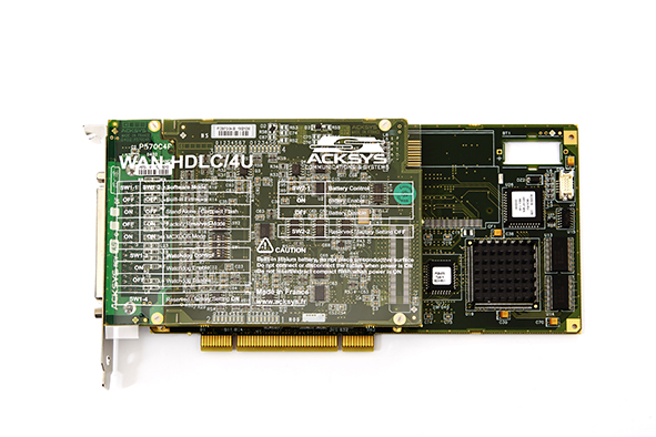


It looks very similar to another French outfit - MAX Technologies - which clearly made its money selling ATE systems to Airbus and to French military. I have some MAX cards (PCMCIA and PCI, ARINC429). These work on the French principle (OK in practice but will never work in theory, so, Serge, this will never work, we need more complexity). MAX are still there, still supporting their old stuff.

https://www.acksys.fr/wp-content/uploads/products/MCXCPCI-570-WAN-HDLC-Hardware-FR_only-DT063.pdf

These cards were done as a tour de force project in digital design. Full of huge FPGAs, and big CPU chips from the 1990s.

Reverse engineering this, even in a narrow bit of functionality, is going to be hard work. For a start, any Modbus-other converter has to deal with register mapping. There is no standard for this. Then HDLC is a big can of worms. It is basically meaningless outside of a specific (originally IBM) context, and here somebody has "bent it" to do something else.

I've done this kind of work ~30 years ago, with FPGAs, but this job is 10x more horrible.

These cards sometimes come up on Ebay.

I suspect whoever specced this project has no idea of the engineering required. It's like, many years ago, the Intel 186 was scarce, and a colleague was tasked with emulating it with 74LS logic.
Z80 Z180 Z280 Z8 S8 8031 8051 H8/300 H8/500 80x86 90S1200 32F417
 

Offline pacioc193Topic starter

  • Regular Contributor
  • *
  • Posts: 57
  • Country: it
Re: RS-485 Synchronous Mode ( CLK + DATA )
« Reply #34 on: July 31, 2023, 04:23:07 pm »
My intention is not to reconstruct the entire board, but only the part necessary for communication with my CPU. The only thing left for me to do is to properly command a transcoder from bit/bang to RS-485.
 

Offline Siwastaja

  • Super Contributor
  • ***
  • Posts: 8180
  • Country: fi
Re: RS-485 Synchronous Mode ( CLK + DATA )
« Reply #35 on: July 31, 2023, 06:58:37 pm »
The level of isolation is not requested... right now we are working on a bench. No high voltage present. Wire lenght 1m.
Classic MAX485 will not work?

To me it sounds like you don't have any real reason for isolation. Frankly, I would use any RS485 transceiver (e.g. MAX485) and add the GND wire which is currently missing between the two systems. It's a very very common misunderstanding that RS485 does not need this wire so even some professionally engineered products fail to have it. Sometimes they still work because of unexpected grounding routes (e.g. through protective earth of building) or parasitics.

Maybe the original products did not have isolation either and therefore did actually kinda pull their grounds together via the RS485 data lines via overvoltage protection (of the transceivers).

But of course not knowing enough about the exact details I can't guarantee this works. Maybe the original thing did have isolation and maybe you need it. I'm just guessing this is not the case.
 
The following users thanked this post: pacioc193

Offline PCB.Wiz

  • Super Contributor
  • ***
  • Posts: 1555
  • Country: au
Re: RS-485 Synchronous Mode ( CLK + DATA )
« Reply #36 on: July 31, 2023, 07:03:36 pm »
Quote
No negative voltage are present on the rail.
It signals across A-B, So a differential bus has positive and negative driven states.
Floating may need some bus biasing to give a stable margin value.

GND connection is inferred, there is a modest common mode tolerance designed to tolerate GND shifts, but fully isolated will not work.


Quote
i'm not able to determinate a working situation that is stable for more than 1 days. I went to launch and the communication was completely off.
I've a working microcontroller software but not a working communication hardware...
Lunch ?
The links I posted include scope shots. How do yours compare ?

‘Stable for even 1 day, is very different from not working hardware.
How many packets pass / fail here ?
 
The following users thanked this post: pacioc193

Offline pacioc193Topic starter

  • Regular Contributor
  • *
  • Posts: 57
  • Country: it
Re: RS-485 Synchronous Mode ( CLK + DATA )
« Reply #37 on: July 31, 2023, 07:12:56 pm »
The level of isolation is not requested... right now we are working on a bench. No high voltage present. Wire lenght 1m.
Classic MAX485 will not work?

To me it sounds like you don't have any real reason for isolation. Frankly, I would use any RS485 transceiver (e.g. MAX485) and add the GND wire which is currently missing between the two systems. It's a very very common misunderstanding that RS485 does not need this wire so even some professionally engineered products fail to have it. Sometimes they still work because of unexpected grounding routes (e.g. through protective earth of building) or parasitics.

Maybe the original products did not have isolation either and therefore did actually kinda pull their grounds together via the RS485 data lines via overvoltage protection (of the transceivers).

But of course not knowing enough about the exact details I can't guarantee this works. Maybe the original thing did have isolation and maybe you need it. I'm just guessing this is not the case.

What i cannot understand is the affermation : RS-485 doesn't need the GND common between all the nodes in the communication bus. This affermation is not true then? Ground must be present and if you don't wan't to share ground you must use some optoisolated transceiver?
I don't have exact detail unlike... just a big challenge for me.
There is not a breakout board for optoisolated rs-485 transceiver to give a shot?


Offline pacioc193Topic starter

  • Regular Contributor
  • *
  • Posts: 57
  • Country: it
Re: RS-485 Synchronous Mode ( CLK + DATA )
« Reply #38 on: July 31, 2023, 07:19:02 pm »
Quote
No negative voltage are present on the rail.
It signals across A-B, So a differential bus has positive and negative driven states.
Floating may need some bus biasing to give a stable margin value.

GND connection is inferred, there is a modest common mode tolerance designed to tolerate GND shifts, but fully isolated will not work.


Quote
i'm not able to determinate a working situation that is stable for more than 1 days. I went to launch and the communication was completely off.
I've a working microcontroller software but not a working communication hardware...
Lunch ?
The links I posted include scope shots. How do yours compare ?

‘Stable for even 1 day, is very different from not working hardware.
How many packets pass / fail here ?


The systems are complete isolated. I'm pretty sure about that because the target has his own power supply and the computer to the destination CPU has just 4 wires : Data(A) Data(B) CLK(A) CLK(B).
I cannot compare with the links that you posted to me.
I replicate the RS-485 communication using bit/bang algorithm generating all the data from the ESP8266, merging ground and the system working very well even without transceiver...
Unluky this is not the definite board. I need the RS485 communication working without a ground cable.

I will try to post some packet analyzing but i don't have with me the one during issue using RS485 transceiver.
 

Offline nctnico

  • Super Contributor
  • ***
  • Posts: 26909
  • Country: nl
    • NCT Developments
Re: RS-485 Synchronous Mode ( CLK + DATA )
« Reply #39 on: July 31, 2023, 07:20:27 pm »
The level of isolation is not requested... right now we are working on a bench. No high voltage present. Wire lenght 1m.
Classic MAX485 will not work?

To me it sounds like you don't have any real reason for isolation. Frankly, I would use any RS485 transceiver (e.g. MAX485) and add the GND wire which is currently missing between the two systems. It's a very very common misunderstanding that RS485 does not need this wire so even some professionally engineered products fail to have it. Sometimes they still work because of unexpected grounding routes (e.g. through protective earth of building) or parasitics.

Maybe the original products did not have isolation either and therefore did actually kinda pull their grounds together via the RS485 data lines via overvoltage protection (of the transceivers).

But of course not knowing enough about the exact details I can't guarantee this works. Maybe the original thing did have isolation and maybe you need it. I'm just guessing this is not the case.

What i cannot understand is the affermation : RS-485 doesn't need the GND common between all the nodes in the communication bus. This affermation is not true then? Ground must be present and if you don't wan't to share ground you must use some optoisolated transceiver?
I don't have exact detail unlike... just a big challenge for me.
There is not a breakout board for optoisolated rs-485 transceiver to give a shot?
RS485 needs a ground reference although some offset (depending on the transceiver is allowed). If you have reason to believe there will be more offset than you transceivers can tolerate, then you'll need an isolated setup. There are complete chips (not cheap) from TI and/or Analog devices that will create an isolated RS485 bridge between two systems.

All in all I suggest you make more measurements and do more research into how the original systems are physically connected where it comes to grounding. AND reverse engineer their driver circuitry to get a full understanding on how the interfaces need to be setup electrically.
 
There are small lies, big lies and then there is what is on the screen of your oscilloscope.
 
The following users thanked this post: Siwastaja, pacioc193

Offline pacioc193Topic starter

  • Regular Contributor
  • *
  • Posts: 57
  • Country: it
Re: RS-485 Synchronous Mode ( CLK + DATA )
« Reply #40 on: July 31, 2023, 07:33:13 pm »
Just to give some idea.

In this capture are present my request and the answer from the CPU.

I bit/bang the Data(A) Data(B) and CLK(A) CLK(B) using the ESP8266 with common GND


This is my TX packet


Using without GND shared, also using commond MAX485, packet analyzer show something like this ( i recreate it manually because i didn't get any image on last try )


Where all 0 were replaced by some voltage ( with oscilloscope i seen that a big jittering appear on the signal ). This happen only if i connet my ESP88266 ( with transceiver or without ) to the slave CPU.

I'm not sure about ground issue but this is my only idea....
« Last Edit: July 31, 2023, 07:35:21 pm by pacioc193 »
 

Offline pacioc193Topic starter

  • Regular Contributor
  • *
  • Posts: 57
  • Country: it
Re: RS-485 Synchronous Mode ( CLK + DATA )
« Reply #41 on: July 31, 2023, 07:48:33 pm »
The level of isolation is not requested... right now we are working on a bench. No high voltage present. Wire lenght 1m.
Classic MAX485 will not work?

To me it sounds like you don't have any real reason for isolation. Frankly, I would use any RS485 transceiver (e.g. MAX485) and add the GND wire which is currently missing between the two systems. It's a very very common misunderstanding that RS485 does not need this wire so even some professionally engineered products fail to have it. Sometimes they still work because of unexpected grounding routes (e.g. through protective earth of building) or parasitics.

Maybe the original products did not have isolation either and therefore did actually kinda pull their grounds together via the RS485 data lines via overvoltage protection (of the transceivers).

But of course not knowing enough about the exact details I can't guarantee this works. Maybe the original thing did have isolation and maybe you need it. I'm just guessing this is not the case.

What i cannot understand is the affermation : RS-485 doesn't need the GND common between all the nodes in the communication bus. This affermation is not true then? Ground must be present and if you don't wan't to share ground you must use some optoisolated transceiver?
I don't have exact detail unlike... just a big challenge for me.
There is not a breakout board for optoisolated rs-485 transceiver to give a shot?
RS485 needs a ground reference although some offset (depending on the transceiver is allowed). If you have reason to believe there will be more offset than you transceivers can tolerate, then you'll need an isolated setup. There are complete chips (not cheap) from TI and/or Analog devices that will create an isolated RS485 bridge between two systems.

All in all I suggest you make more measurements and do more research into how the original systems are physically connected where it comes to grounding. AND reverse engineer their driver circuitry to get a full understanding on how the interfaces need to be setup electrically.
 

There is not possibility to communicate with another system without using any kind of ground?
Watching the classic MAX485 tranceiver is not showing anywhere that the system must share ground


This is a my big mental limitation...
 

Offline PCB.Wiz

  • Super Contributor
  • ***
  • Posts: 1555
  • Country: au
Re: RS-485 Synchronous Mode ( CLK + DATA )
« Reply #42 on: July 31, 2023, 08:11:49 pm »
Quote
The systems are complete isolated. I'm pretty sure about that because the target has his own power supply and the computer to the destination CPU has just 4 wires : Data(A) Data(B) CLK(A) CLK(B)
The mains supply surely has a ground ?
Just run a Gnd cable and test it.

Quote
There is not possibility to communicate with another system without using any kind of ground?
Watching the classic MAX485 transceiver is not showing anywhere that the system must share ground
Classic MAX485 has common mode voltage limits, it is not fully isolated

Yes, google ISOLATED RS485
That has usually opto couplers and switching isolated power supplies added to ‘vanilla’ rs485
 

Offline nctnico

  • Super Contributor
  • ***
  • Posts: 26909
  • Country: nl
    • NCT Developments
Re: RS-485 Synchronous Mode ( CLK + DATA )
« Reply #43 on: July 31, 2023, 08:17:23 pm »
The level of isolation is not requested... right now we are working on a bench. No high voltage present. Wire lenght 1m.
Classic MAX485 will not work?

To me it sounds like you don't have any real reason for isolation. Frankly, I would use any RS485 transceiver (e.g. MAX485) and add the GND wire which is currently missing between the two systems. It's a very very common misunderstanding that RS485 does not need this wire so even some professionally engineered products fail to have it. Sometimes they still work because of unexpected grounding routes (e.g. through protective earth of building) or parasitics.

Maybe the original products did not have isolation either and therefore did actually kinda pull their grounds together via the RS485 data lines via overvoltage protection (of the transceivers).

But of course not knowing enough about the exact details I can't guarantee this works. Maybe the original thing did have isolation and maybe you need it. I'm just guessing this is not the case.

What i cannot understand is the affermation : RS-485 doesn't need the GND common between all the nodes in the communication bus. This affermation is not true then? Ground must be present and if you don't wan't to share ground you must use some optoisolated transceiver?
I don't have exact detail unlike... just a big challenge for me.
There is not a breakout board for optoisolated rs-485 transceiver to give a shot?
RS485 needs a ground reference although some offset (depending on the transceiver is allowed). If you have reason to believe there will be more offset than you transceivers can tolerate, then you'll need an isolated setup. There are complete chips (not cheap) from TI and/or Analog devices that will create an isolated RS485 bridge between two systems.

All in all I suggest you make more measurements and do more research into how the original systems are physically connected where it comes to grounding. AND reverse engineer their driver circuitry to get a full understanding on how the interfaces need to be setup electrically.
 

There is not possibility to communicate with another system without using any kind of ground?
Watching the classic MAX485 tranceiver is not showing anywhere that the system must share ground


This is a my big mental limitation...
The clue is in the absolute maximum voltage ratings for the receiver (A/ B) pins and the current limits at the extremes of the common mode voltage.
There are small lies, big lies and then there is what is on the screen of your oscilloscope.
 

Offline pacioc193Topic starter

  • Regular Contributor
  • *
  • Posts: 57
  • Country: it
Re: RS-485 Synchronous Mode ( CLK + DATA )
« Reply #44 on: July 31, 2023, 08:27:08 pm »
Quote
The systems are complete isolated. I'm pretty sure about that because the target has his own power supply and the computer to the destination CPU has just 4 wires : Data(A) Data(B) CLK(A) CLK(B)
The mains supply surely has a ground ?
Just run a Gnd cable and test it.

Quote
There is not possibility to communicate with another system without using any kind of ground?
Watching the classic MAX485 transceiver is not showing anywhere that the system must share ground
Classic MAX485 has common mode voltage limits, it is not fully isolated

Yes, google ISOLATED RS485
That has usually opto couplers and switching isolated power supplies added to ‘vanilla’ rs485

Something like this could be used to test if the solution is to use isolated?

https://wiki.dfrobot.com/Gravity_Active_Isolated_RS485_to_UART_Signal_Converter_SKU_DFR0845

Or better

https://digilent.com/reference/pmod/pmodrs485/reference-manual
« Last Edit: July 31, 2023, 08:38:55 pm by pacioc193 »
 

Offline PCB.Wiz

  • Super Contributor
  • ***
  • Posts: 1555
  • Country: au
Re: RS-485 Synchronous Mode ( CLK + DATA )
« Reply #45 on: July 31, 2023, 09:07:14 pm »

Something like this could be used to test if the solution is to use isolated?

https://wiki.dfrobot.com/Gravity_Active_Isolated_RS485_to_UART_Signal_Converter_SKU_DFR0845

Or better

https://digilent.com/reference/pmod/pmodrs485/reference-manual

Yes, the 'or better' is much better. I was about to find an example.

That has optional DE,REN lines, that control the directions and drivers, the simpler kludge ones hide that internally, and you already do SW control, so you can add DE_REN drive.

Addit: it also has separate TX/RX, as in RS422, which is what you actually want - note your host has separate pins, so just wire to those, and simplify DE_REN. (always on)

The old PCI board is the following : MCXCPCI-570-WAN-HDLC

pin   2 TxD Transmit Data Output (A)    pin 14 TxD Transmit Data Output (B)
pin 11 TxClkOut Transmit Clock Output (B)   pin 24 TxClkOut Transmit Clock Output (A)

pin   3 RxD Receive Data Input (A)   pin 16 RxD Receive Data Input (B)
pin   9 RxClkIn Receive Clock Input (B) pin 17 RxClkIn Receive Clock Input (A)


Your SW side always listens to the remote TXD lines and drives the remote RXD lines.
« Last Edit: July 31, 2023, 09:31:39 pm by PCB.Wiz »
 

Offline PCB.Wiz

  • Super Contributor
  • ***
  • Posts: 1555
  • Country: au
Re: RS-485 Synchronous Mode ( CLK + DATA )
« Reply #46 on: July 31, 2023, 09:14:08 pm »
Just to give some idea.

In this capture are present my request and the answer from the CPU.

I bit/bang the Data(A) Data(B) and CLK(A) CLK(B) using the ESP8266 with common GND
These seem to show some quasi differential signal, as they idle at the same voltage (wrong for differential). ?
Are you driving all 4 lines in software ? Normal would be to generate Data and CLK and use the transceiver hardware to do the differential drive.
 

Offline pacioc193Topic starter

  • Regular Contributor
  • *
  • Posts: 57
  • Country: it
Re: RS-485 Synchronous Mode ( CLK + DATA )
« Reply #47 on: July 31, 2023, 09:23:26 pm »
Just to give some idea.

In this capture are present my request and the answer from the CPU.

I bit/bang the Data(A) Data(B) and CLK(A) CLK(B) using the ESP8266 with common GND
These seem to show some quasi differential signal, as they idle at the same voltage (wrong for differential). ?
Are you driving all 4 lines in software ? Normal would be to generate Data and CLK and use the transceiver hardware to do the differential drive.

Yes I generate all 4 lines in software via bit/bang algo and I confirm that the CPU is accepting also this kind of signal.
I know is not a pure rs485 signal but from my limitate knowledge I was thinking that gnd could not be used with transceiver.
Could be possible that a not connected gnd lines generate that jittering on the AB channel of the rs485 lines?

 I will give a try with this opto isolated transceiver and give a feedback. Thanks for all the patience.
 

Offline PCB.Wiz

  • Super Contributor
  • ***
  • Posts: 1555
  • Country: au
Re: RS-485 Synchronous Mode ( CLK + DATA )
« Reply #48 on: July 31, 2023, 09:49:26 pm »
Yes I generate all 4 lines in software via bit/bang algo and I confirm that the CPU is accepting also this kind of signal.
I know is not a pure rs485 signal but from my limitate knowledge I was thinking that gnd could not be used with transceiver.

The basic idea is good, and is a way to get some echo out of the remote unit, as a sign-of-life test. It sounds like you do have echoes ?
I would clean up the SW idle states so they are truly differential ( B lines = !A lines  always)

that will work to test these lines
pin   3 RxD Receive Data Input (A)   pin 16 RxD Receive Data Input (B)
pin   9 RxClkIn Receive Clock Input (B) pin 17 RxClkIn Receive Clock Input (A)


 you cannot just wire your MCU to the other direction wires, but you can scope them and confirm a packet replies as expected.

to test
pin   2 TxD Transmit Data Output (A)    pin 14 TxD Transmit Data Output (B)
pin 11 TxClkOut Transmit Clock Output (B)   pin 24 TxClkOut Transmit Clock Output (A)

to your MCU, you need 2 x differential receivers.
An H11L1 optocoupler might be pressed into quick bench test use, so you can sample the echo as CMOS levels.
The digilent RS485/RS422 is a proper solution,  but you may want to test something while waiting for that to arrive  8)

Addit: another alternative, non-isolated?**  RS422 equivalent  - gives TTL to DIFF x2, order time choice of 3.3V / 5V
https://www.aliexpress.com/item/1005004149339932.html
better images
https://www.aliexpress.com/item/1005004933919596.html

** I think that is isolated, the ADUM3201ARZ is a one each way isolator and the black block, looks like a small DC-DC
« Last Edit: August 01, 2023, 03:03:58 am by PCB.Wiz »
 

Offline pacioc193Topic starter

  • Regular Contributor
  • *
  • Posts: 57
  • Country: it
Re: RS-485 Synchronous Mode ( CLK + DATA )
« Reply #49 on: August 01, 2023, 06:50:40 am »
Yes I generate all 4 lines in software via bit/bang algo and I confirm that the CPU is accepting also this kind of signal.
I know is not a pure rs485 signal but from my limitate knowledge I was thinking that gnd could not be used with transceiver.

The basic idea is good, and is a way to get some echo out of the remote unit, as a sign-of-life test. It sounds like you do have echoes ?
I would clean up the SW idle states so they are truly differential ( B lines = !A lines  always)

that will work to test these lines
pin   3 RxD Receive Data Input (A)   pin 16 RxD Receive Data Input (B)
pin   9 RxClkIn Receive Clock Input (B) pin 17 RxClkIn Receive Clock Input (A)


 you cannot just wire your MCU to the other direction wires, but you can scope them and confirm a packet replies as expected.

to test
pin   2 TxD Transmit Data Output (A)    pin 14 TxD Transmit Data Output (B)
pin 11 TxClkOut Transmit Clock Output (B)   pin 24 TxClkOut Transmit Clock Output (A)

to your MCU, you need 2 x differential receivers.
An H11L1 optocoupler might be pressed into quick bench test use, so you can sample the echo as CMOS levels.
The digilent RS485/RS422 is a proper solution,  but you may want to test something while waiting for that to arrive  8)

Addit: another alternative, non-isolated?**  RS422 equivalent  - gives TTL to DIFF x2, order time choice of 3.3V / 5V
https://www.aliexpress.com/item/1005004149339932.html
better images
https://www.aliexpress.com/item/1005004933919596.html

** I think that is isolated, the ADUM3201ARZ is a one each way isolator and the black block, looks like a small DC-DC

Thanks so much for all this kindly information.
Yes opencollector optoisolator could be a good idea for check if the CPU answer.
I've found on digikey the digilent breakout board, couple of day and i will continue my research.

I don't want to take something on aliexpress that is not sure about the real working principle.

Thanks !
 
The following users thanked this post: PCB.Wiz

Offline ag123

  • Contributor
  • Posts: 39
  • Country: 00
Re: RS-485 Synchronous Mode ( CLK + DATA )
« Reply #50 on: August 01, 2023, 07:05:44 am »
think clk is normally not 'bundled' in RS485 implementations and that clk & 'synchronous' is probably some "propriety" phy and protocols.
as i didn't work much with RS485, hence, I'd leave it at that.
for 'simple' implementations, i'd just use a uart to interface it.

async 'clock recovery' is 'difficult' and hence I'd guess the designers just made it 'synchronous' by putting a clk line, but that clk on its own can also be noisy or be slew limited (long lines practically work like rlc filters) and possibly limit the distance/length possible.

I think differential signalling
https://en.wikipedia.org/wiki/Differential_signalling
works like flipping the battery between the +/- signals forward and reverse literally. Hence, it is possibly 'easier' to use a transceiver e.g. rs485 / rs422 to translate the signals back to the 'normal' 0 and 1 signals.
« Last Edit: August 01, 2023, 07:21:04 am by ag123 »
 
The following users thanked this post: pacioc193

Offline Smokey

  • Super Contributor
  • ***
  • Posts: 2597
  • Country: us
  • Not An Expert
Re: RS-485 Synchronous Mode ( CLK + DATA )
« Reply #51 on: August 01, 2023, 07:29:22 am »
Read what the OP wrote: the systems don't share a common ground. In such cases it is better to use AC coupling and not rely on wether the ground is connected somewhere or not. IIRC ISDN2 is an example which uses HDLC over AC coupled links.

Again: it would be wise for the OP to investigate whether the links are AC coupled or not or that there are other measures to deal with ground offsets (which can include using transceivers with increased common mode ranges).

Isolated transceivers solve the lack of ground maybe?
https://www.ti.com/isolation/isolated-interfaces/rs-485-transceivers/overview.html
 

Offline pacioc193Topic starter

  • Regular Contributor
  • *
  • Posts: 57
  • Country: it
Re: RS-485 Synchronous Mode ( CLK + DATA )
« Reply #52 on: August 01, 2023, 10:14:33 am »
Read what the OP wrote: the systems don't share a common ground. In such cases it is better to use AC coupling and not rely on wether the ground is connected somewhere or not. IIRC ISDN2 is an example which uses HDLC over AC coupled links.

Again: it would be wise for the OP to investigate whether the links are AC coupled or not or that there are other measures to deal with ground offsets (which can include using transceivers with increased common mode ranges).

Isolated transceivers solve the lack of ground maybe?
https://www.ti.com/isolation/isolated-interfaces/rs-485-transceivers/overview.html

Yes, as already suggested by PCB.Wiz the solution could be to use a isolated transceivers.
I will test and let you know.


Offline harerod

  • Frequent Contributor
  • **
  • Posts: 449
  • Country: de
  • ee - digital & analog
    • My services:
Re: RS-485 Synchronous Mode ( CLK + DATA )
« Reply #53 on: August 01, 2023, 02:51:28 pm »
Keyword: SSI - Synchronous Serial Interface

This is an industry standard for encoder communication. My first implementations have been on FPGA's. About ten years ago I switched to STM32 - e.g. https://www.harerod.de/applications_eng.html#SSI_USB
A STM32F405 will handle 2MHz in slave mode (sensor emulation) without any sweat. In master mode the transceiver chips limit clock to 10MHz on that board.

Another limitation, for which exist partial software remedies, is the reduced lightspeed in cables. For CAT5 that would be about two thirds of the speed of light in vacuum.
 

Offline pacioc193Topic starter

  • Regular Contributor
  • *
  • Posts: 57
  • Country: it
Re: RS-485 Synchronous Mode ( CLK + DATA )
« Reply #54 on: August 01, 2023, 03:06:17 pm »
Keyword: SSI - Synchronous Serial Interface

This is an industry standard for encoder communication. My first implementations have been on FPGA's. About ten years ago I switched to STM32 - e.g. https://www.harerod.de/applications_eng.html#SSI_USB
A STM32F405 will handle 2MHz in slave mode (sensor emulation) without any sweat. In master mode the transceiver chips limit clock to 10MHz on that board.

Another limitation, for which exist partial software remedies, is the reduced lightspeed in cables. For CAT5 that would be about two thirds of the speed of light in vacuum.


I worked with this MCU but the SSI is a fake communication... it use a USART communication adding a clock on the right byte. It is 8bit aligned and for each data that i write on the bus, a lot of time is lost due a empty time spend to generate signal of start bit, parity bit, stop bit ecc ecc

I preferred to bit bang it....
 

Offline pacioc193Topic starter

  • Regular Contributor
  • *
  • Posts: 57
  • Country: it
Re: RS-485 Synchronous Mode ( CLK + DATA )
« Reply #55 on: September 07, 2023, 07:00:05 pm »
Test continue and the project is not yet finished….
I’ve tested with isolated converter and communication seems works but not in the correct ways…
Is there any equipment to check the isolated 485 signal without transceiver it to ttl?
Like oscilloscope or logic analyzer . Is impossible for me to get the ground from the destination cpu… I’ve already tested to use the ground from power supply but the signal is not present into a classic clone logic analyzer.
Any tips?
 

Offline pacioc193Topic starter

  • Regular Contributor
  • *
  • Posts: 57
  • Country: it
Re: RS-485 Synchronous Mode ( CLK + DATA )
« Reply #56 on: September 11, 2023, 09:54:39 am »
Finally i understood the problem...

Protocol is HDLC that force a bit stuffing when a more than 5 bit are "1" consecutively.

The byte 0x5F ->  0101 1111 will be translate to  0 1001 1111 (0x09F) to avoid the flag 0x7E misinterpreted.

My board then is working well... I need just to correct the reading from my custom mcu in order to implement this behaviour.
 
The following users thanked this post: PCB.Wiz

Offline jjcrawford1990

  • Newbie
  • Posts: 2
  • Country: gb
Re: RS-485 Synchronous Mode ( CLK + DATA )
« Reply #57 on: January 21, 2024, 06:26:05 am »
Fascinating read. I had a similar problem having to find hardware to communicate with an RS485 Synchronous HDLC device in the railway, I searched for an off the shelf piece of equipment for a while before finding one. However the SDK was horribly complex and although I got it working, I’d love something simpler (comparatively)

If you would be willing to share any of the design, it’d be fascinating


Share me

Digg  Facebook  SlashDot  Delicious  Technorati  Twitter  Google  Yahoo
Smf