Author Topic: Swapping 7805 with Buck Converter  (Read 7431 times)

0 Members and 2 Guests are viewing this topic.

Offline axeonicTopic starter

  • Contributor
  • Posts: 29
  • Country: us
Swapping 7805 with Buck Converter
« on: July 20, 2026, 03:48:37 am »
Hello,

I have a circuit board that I've made for the Teensy 4.0 and Audio board. Currently using a 7805 with a 9V power adapter. The 7805 gets very hot, so thinking about using the muRata OKI-78SR-5/1.5-W36-C. https://www.lcsc.com/product-detail/C6134431.html?s_z=n_q_C6134431&globalKeyword=C6134431
(Q1 is just a p-channel mosfet that I use for reverse polarity protection).

Would I need to change any caps in my schematic?
Thanks in advance, very much appreciated.

TonyA
 

Online Smokey

  • Super Contributor
  • ***
  • Posts: 3887
  • Country: us
  • Not An Expert
Re: Swapping 7805 with Buck Converter
« Reply #1 on: July 20, 2026, 06:11:06 am »
« Last Edit: July 21, 2026, 10:51:25 pm by Smokey »
 
The following users thanked this post: axeonic

Offline axeonicTopic starter

  • Contributor
  • Posts: 29
  • Country: us
Re: Swapping 7805 with Buck Converter
« Reply #2 on: July 20, 2026, 07:10:14 am »
Thank you. It's $5.00 on digikey. Yes, the LCSC part is twice the price as on Digikey. Don't know why. But I'm going with Digikey, soldering it myself.

Thanks.
« Last Edit: July 20, 2026, 07:15:08 am by axeonic »
 

Offline MarkF

  • Super Contributor
  • ***
  • Posts: 3297
  • Country: us
Re: Swapping 7805 with Buck Converter
« Reply #3 on: July 20, 2026, 11:46:34 am »
It sounds like there is something else going on that you should look into?

I'm using a MCP1703T-5002E/DB  5V regulator with a 9V battery for a PCB with a PIC18F2630 and a 1.2" OLED display that does not get hot.  If I remember correctly, the max current draw is 150mA or less.

I'm also using a 3.3V version on the same PCB direct from the battery to drive a nRF24L01+ transceiver.  Neither get hot.
 
The following users thanked this post: axeonic

Offline peter-h

  • Super Contributor
  • ***
  • Posts: 6067
  • Country: gb
  • Doing electronics since the 1960s...
Re: Swapping 7805 with Buck Converter
« Reply #4 on: July 20, 2026, 01:49:00 pm »
Funny thing... I am also looking for a similar part, but I would like more than 36V max input, and there isn't a lot out there.
Z80 Z180 Z280 Z8 S8 8031 8051 H8/300 H8/500 80x86 90S1200 32F417
 

Offline SiliconWizard

  • Super Contributor
  • ***
  • Posts: 17810
  • Country: fr
Re: Swapping 7805 with Buck Converter
« Reply #5 on: July 20, 2026, 04:36:52 pm »
Funny thing... I am also looking for a similar part, but I would like more than 36V max input, and there isn't a lot out there.

You have the TLVM65030 which is a new product at an attractive price (and so hard to source)  or the older TPSM5601R5 which is available (sort of) but more expensive.
To keep costs down and have better availability, I would suggest designing your own with a buck converter directly. If 48V is ok, you have the MCP16362T. TI has a number of such bucks, availability can be a problem though.
 
The following users thanked this post: peter-h

Offline peter-h

  • Super Contributor
  • ***
  • Posts: 6067
  • Country: gb
  • Doing electronics since the 1960s...
Re: Swapping 7805 with Buck Converter
« Reply #6 on: July 20, 2026, 09:56:09 pm »
The MCP16362T seems to be very good.

The MCP16363 looks even better, with its +/-10% spread spectrum ;) I often wonder how much extra work is needed for these super fast switchers to get through EMC. Many years ago I designed a flyback multi output isolated PSU, around an amorphous metal toroid, TL5001CD, and it got built in tens of k over 30 years, passed all the EMC testing multiple times, ~100kHz, zero failures, but is a bit of an overkill for this new project which does not need isolation.

I need 5V 1A.
Z80 Z180 Z280 Z8 S8 8031 8051 H8/300 H8/500 80x86 90S1200 32F417
 

Offline peter-h

  • Super Contributor
  • ***
  • Posts: 6067
  • Country: gb
  • Doing electronics since the 1960s...
Re: Swapping 7805 with Buck Converter
« Reply #7 on: July 21, 2026, 09:52:18 pm »
I wonder how horrible it is to achieve any sort of EMC compliance with these simple circuits...
Z80 Z180 Z280 Z8 S8 8031 8051 H8/300 H8/500 80x86 90S1200 32F417
 

Online daisizhou

  • Super Contributor
  • ***
  • Posts: 1855
  • Country: cn
Re: Swapping 7805 with Buck Converter
« Reply #8 on: July 21, 2026, 10:19:16 pm »
Hello,

I have a circuit board that I've made for the Teensy 4.0 and Audio board. Currently using a 7805 with a 9V power adapter. The 7805 gets very hot, so thinking about using the muRata OKI-78SR-5/1.5-W36-C. https://www.lcsc.com/product-detail/C6134431.html?s_z=n_q_C6134431&globalKeyword=C6134431
(Q1 is just a p-channel mosfet that I use for reverse polarity protection).

Would I need to change any caps in my schematic?
Thanks in advance, very much appreciated.

TonyA

In my opinion, your circuit design is somewhat outdated. A DC-DC step-down circuit could easily accomplish this now.

I've attached a simple MP2315 example circuit.

On a side note, judging from the circuit diagram, you could easily use a lithium-ion battery; your old solution seems to still be using a traditional lead-acid battery.
daisizhou#sina.com #=@
 
The following users thanked this post: axeonic

Offline axeonicTopic starter

  • Contributor
  • Posts: 29
  • Country: us
Re: Swapping 7805 with Buck Converter
« Reply #9 on: July 21, 2026, 10:56:08 pm »
Thank you. Here is the complete schematic. There will be 3 more rotary encoders (on the left) connected in my next revision.
Yes, the 9V battery I've been using doesn't work well. Thank you for the info and schematics!
 

Offline MarkF

  • Super Contributor
  • ***
  • Posts: 3297
  • Country: us
Re: Swapping 7805 with Buck Converter
« Reply #10 on: July 21, 2026, 11:20:10 pm »
Your schematic indicates that you want to use PEC11 encoders.
I highly recommend that you implement the pull-up and filter shown in the PEC11 datasheet.
Don't cheap out and think you don't need it.  You do!

I used a PEC11 encoder in my model railroad throttle (see below).

Also, I'm getting 4 to 5 hours of usage from a standard 9V battery.
But you really need to power down high current peripherals as much as possible.

2862208-0
 
The following users thanked this post: axeonic

Offline SiliconWizard

  • Super Contributor
  • ***
  • Posts: 17810
  • Country: fr
Re: Swapping 7805 with Buck Converter
« Reply #11 on: July 21, 2026, 11:44:39 pm »
The MCP16362T seems to be very good.
The MCP16363 looks even better, with its +/-10% spread spectrum ;) I often wonder how much extra work is needed for these super fast switchers to get through EMC.

Well, they do operate at higher frequencies, but the plus side is that they only require relatively low inductance, so the inductors are smaller (even much smaller, considering inductance is lower and so they can be small while having low ESR), you can easily find them shielded. And the overall PCB area is also pretty small, so you can contain the noise in a small area. With careful layout and a pi filter in front of the buck converter, EMC should not be too hard to meet.
 
The following users thanked this post: peter-h, axeonic

Online daisizhou

  • Super Contributor
  • ***
  • Posts: 1855
  • Country: cn
Re: Swapping 7805 with Buck Converter
« Reply #12 on: July 22, 2026, 12:17:10 am »
Thank you. Here is the complete schematic. There will be 3 more rotary encoders (on the left) connected in my next revision.
Yes, the 9V battery I've been using doesn't work well. Thank you for the info and schematics!

You can use two 18650 or 21700 batteries to form an 8.4V battery pack, using the TP5100 charging management solution.

Alternatively, you can choose to use three lithium batteries in series to form a 12.6V battery pack, and then connect a DC-DC converter to stabilize the voltage at 9V. This will allow for a wider operating range.
daisizhou#sina.com #=@
 

Online daisizhou

  • Super Contributor
  • ***
  • Posts: 1855
  • Country: cn
Re: Swapping 7805 with Buck Converter
« Reply #13 on: July 22, 2026, 01:32:44 am »
You can use two 18650 or 21700 batteries to form an 8.4V battery pack, using the TP5100 charging management solution.

Alternatively, you can choose to use three lithium batteries in series to form a 12.6V battery pack, and then connect a DC-DC converter to stabilize the voltage at 9V. This will allow for a wider operating range.

This doesn't make sense since his device operates on 5V.  I think it would be better to have a USB power input and use a packaged power bank for battery operation.

What I mean is that he needs a DC-DC converter board similar to the MP2315, so that the final output of this converter board is 5.0V. As for the input voltage, it can be any 2S or 3S lithium battery.
daisizhou#sina.com #=@
 

Offline peter-h

  • Super Contributor
  • ***
  • Posts: 6067
  • Country: gb
  • Doing electronics since the 1960s...
Re: Swapping 7805 with Buck Converter
« Reply #14 on: August 06, 2026, 06:15:08 am »
As an update, I found the MCP16366
https://ww1.microchip.com/downloads/aemDocuments/documents/APID/ProductDocuments/DataSheets/MCP16364-5-6-Family-Data-Sheet-DS20006969.pdf
which does 5V 1A and does not do the discontinuous mode which the MCP16362 does and which is undesirable in lots of applications.

Now digging around input filtering
https://www.eevblog.com/forum/projects/instability-due-to-transfer-function-peaking/msg6327816/#msg6327816
« Last Edit: August 06, 2026, 10:03:47 am by peter-h »
Z80 Z180 Z280 Z8 S8 8031 8051 H8/300 H8/500 80x86 90S1200 32F417
 
The following users thanked this post: axeonic

Offline peter-h

  • Super Contributor
  • ***
  • Posts: 6067
  • Country: gb
  • Doing electronics since the 1960s...
Re: Swapping 7805 with Buck Converter
« Reply #15 on: September 15, 2026, 09:45:31 pm »
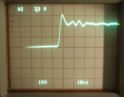
I built the PCB with the MSP16366 and wonder how the hell can one get the (anticipated) radiation down. With a 400Mhz scope, I see a < 5ns risetime to Vin when the mosfet turns on.

It is on a ground plane PCB so the bottom is shielded, and I have a metal case covering the components. So all around metal shielding, but... Rarely one sees something switch this fast!

Not much ringing


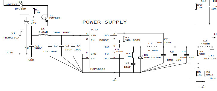
The input components are there just for protection from automotive spikes etc.

Currently I have nothing for R3/C6.

I've tried a quick hack to slow down that fast rising edge, with a resistor in series with pin 8. 1R does nothing, 10R does nothing, and 47R makes the switcher go really funny. This is measuring the waveform at the top of the schottky diode. Virtually no difference in the edge.

A zero risetime square wave voltage applied to a perfect inductor produces a current ramp but the inductor will also have a parasitic capacitance which will cause a current spike.

So I will have to live with this and hope the layout and shielding are good enough. It would surprise me if this chip was useless due to this.
« Last Edit: September 16, 2026, 09:48:54 am by peter-h »
Z80 Z180 Z280 Z8 S8 8031 8051 H8/300 H8/500 80x86 90S1200 32F417
 
The following users thanked this post: axeonic

Offline peter-h

  • Super Contributor
  • ***
  • Posts: 6067
  • Country: gb
  • Doing electronics since the 1960s...
Re: Swapping 7805 with Buck Converter
« Reply #16 on: September 16, 2026, 06:29:05 pm »
I made it as compact as possible - like the layout in the Microchip DS


and with the metal case it will be shielded on all six sides, but ferrous shielded on only top 4 sides (although the bottom will have a 1.8mm aluminium case behind it).

The D3 oversize pads are from the previous 3A design. This 1A design uses smaller parts, and higher value inductors. Actually I used the same physical size inductors as the 3A design used... lower resistance.

Vref is super accurate - I am getting within 0.1%.

The capacitors etc were as per the DS, even though most were at silly prices.
« Last Edit: September 16, 2026, 07:03:43 pm by peter-h »
Z80 Z180 Z280 Z8 S8 8031 8051 H8/300 H8/500 80x86 90S1200 32F417
 

Offline SiliconWizard

  • Super Contributor
  • ***
  • Posts: 17810
  • Country: fr
Re: Swapping 7805 with Buck Converter
« Reply #17 on: September 16, 2026, 07:57:14 pm »
Any decent switching converter will show steep switching edges - degrading them can only lead to decreased efficiency. Instead of trying series resistors, you could have picked inductors with higher ESR, but the result would be similar: worse efficiency, higher temperature.

The MCP16366 has spread spectrum (which they call "Switching Frequency Dithering"), so that will spread the emissions over a larger bandwidth, lowering peaks for any particular frequency, which is way better for EMI. You can check it out by looking at the switching period on the scope rather than just the rising edge.

 
The following users thanked this post: Smokey

Offline mariush

  • Super Contributor
  • ***
  • Posts: 5346
  • Country: ro
  • .
Re: Swapping 7805 with Buck Converter
« Reply #18 on: September 16, 2026, 08:44:52 pm »
I'd say the first step should be ditching the 9v battery, it's really a poor choice.

I'd try to use a buck-boost regulator, maybe Richtek RT6154 for example : https://www.digikey.com/en/products/detail/richtek-usa-inc/RT6154AGQW/5820047   / https://www.lcsc.com/product-detail/C250400.html

You can see on page 9 of the datasheet that it can do even 2.8v to 4.5v at close to 2A output current, more with higher input voltage (nearly 3A with 3.7v input). IC can boost to 5v, no problem. 

Another good example is ISL91110 for example : https://www.digikey.com/en/products/detail/renesas-electronics-corporation/ISL91110IIAZ-T7A/4805976

May look scary with 25 bga balls but in reality lots of balls can be joined together, Vin,Vout,LX1 and LX2 all use 4 consecutive pads...

A 26650 LiFePO4 will have 3.6v when charged, and go down to 3v as it discharges and about same capacity as a regular 18650 lithium battery, but with safer, with more recharge cycles ... even the  Renesas regulator should boost to 5v and up to ~1.2A easily, with 3v or more input.

3 alkaline AA cells would also work (4.5v if alkaline, 3 x 1.1-1.35v if rechargeable)
 
The following users thanked this post: axeonic

Offline peter-h

  • Super Contributor
  • ***
  • Posts: 6067
  • Country: gb
  • Doing electronics since the 1960s...
Re: Swapping 7805 with Buck Converter
« Reply #19 on: September 16, 2026, 08:47:47 pm »
Quote
Any decent switching converter will show steep switching edges - degrading them can only lead to decreased efficiency. Instead of trying series resistors, you could have picked inductors with higher ESR, but the result would be similar: worse efficiency, higher temperature.
The MCP16366 has spread spectrum (which they call "Switching Frequency Dithering"), so that will spread the emissions over a larger bandwidth, lowering peaks for any particular frequency, which is way better for EMI. You can check it out by looking at the switching period on the scope rather than just the rising edge.

I tried inductors too but it does not help.

Yes I can readily see the frequency variation. I just did not post a photo showing that ;)

I think there is a tradeoff between higher switching speeds (and higher efficiency) and more emissions, and lower switching speeds and worse efficiency but less emissions.

There are ways to do it but they involve more components and get well away from the simplicity of these circuits. One can use capacitors to absorb some energy to slow down the edges. I used to do that on HV power supplies and it was done partly to keep the semiconductors inside the SOA region.
Z80 Z180 Z280 Z8 S8 8031 8051 H8/300 H8/500 80x86 90S1200 32F417
 

Online Smokey

  • Super Contributor
  • ***
  • Posts: 3887
  • Country: us
  • Not An Expert
Re: Swapping 7805 with Buck Converter
« Reply #20 on: September 16, 2026, 09:38:58 pm »
If this wasn't an integrated converter with internal fets you could increase the gate resistors to slow down the switching.  Not a lot of options when everything is in a potted box.  Everything is a compromise right...
 

Online uer166

  • Super Contributor
  • ***
  • Posts: 1275
  • Country: us
Re: Swapping 7805 with Buck Converter
« Reply #21 on: September 16, 2026, 10:01:37 pm »
What exactly is the problem you're trying to solve? Fast edges on a DCDC switching node are expected in high density or efficient designs.

If layed out well its not a problem. One fun issue to watch out for is inductor inter-winding capacitance that couples that edge to the output directly: you want the highest SRF inductors with minimal capacitance to reduce that.
 
The following users thanked this post: Smokey

Offline peter-h

  • Super Contributor
  • ***
  • Posts: 6067
  • Country: gb
  • Doing electronics since the 1960s...
Re: Swapping 7805 with Buck Converter
« Reply #22 on: September 17, 2026, 06:26:54 am »
Quote
inductor inter-winding capacitance that couples that edge to the output directly

Yes; that is exactly the problem with fast switching.

I have an extra output filter (L3 in above circuit) which uses a high SRF chip inductor - MLP2520HR47MT0S1 which is somewhere around 100MHz. But those fast edges are still producing high currents in any loop area which will radiate out, regardless of any further output filtering. The main converter inductor is 6.8uH MSS1048-682NLC whose SRF is listed at 35MHz.

It isn't possible to do a layout with a zero loop area :)

It is for these reasons that practically all DC-DC converters (which nowadays tend to run at MHz speeds) needs loads of external filtering to meet any EMC specs.
« Last Edit: September 17, 2026, 08:26:17 am by peter-h »
Z80 Z180 Z280 Z8 S8 8031 8051 H8/300 H8/500 80x86 90S1200 32F417
 

Offline axeonicTopic starter

  • Contributor
  • Posts: 29
  • Country: us
Re: Swapping 7805 with Buck Converter
« Reply #23 on: September 17, 2026, 06:37:53 am »
I'd say the first step should be ditching the 9v battery, it's really a poor choice.

I'd try to use a buck-boost regulator, maybe Richtek RT6154 for example : https://www.digikey.com/en/products/detail/richtek-usa-inc/RT6154AGQW/5820047   / https://www.lcsc.com/product-detail/C250400.html

You can see on page 9 of the datasheet that it can do even 2.8v to 4.5v at close to 2A output current, more with higher input voltage (nearly 3A with 3.7v input). IC can boost to 5v, no problem. 

Another good example is ISL91110 for example : https://www.digikey.com/en/products/detail/renesas-electronics-corporation/ISL91110IIAZ-T7A/4805976

May look scary with 25 bga balls but in reality lots of balls can be joined together, Vin,Vout,LX1 and LX2 all use 4 consecutive pads...

A 26650 LiFePO4 will have 3.6v when charged, and go down to 3v as it discharges and about same capacity as a regular 18650 lithium battery, but with safer, with more recharge cycles ... even the  Renesas regulator should boost to 5v and up to ~1.2A easily, with 3v or more input.

3 alkaline AA cells would also work (4.5v if alkaline, 3 x 1.1-1.35v if rechargeable)

Thank you. I did get rid of the 9V. The 3 AA cells might be an option but for now just using a 9V power supply adapter.


Share me

Digg  Facebook  SlashDot  Delicious  Technorati  Twitter  Google  Yahoo
Smf


-->