A question: why are some of these screens called 16-bit, 24-bit?
It refers to the number of colors the RGB/LVDS/MIPI DSI display can reproduce,
or to the 8080/68k data bus width. So, it depends on the interface.
Most often, 16-bit color uses RGB565, which means you have 2⁵ = 32 possible red intensities, 2⁶ = 64 possible green intensities, and 2⁵ = 32 possible blue intensities. Human eye is slightly more sensitive to green than it is to blue or red, which is why it makes sense to use the extra bit for green.
Most common is 18-bit color, RGB666, where red, green, and blue all have 64 possible intensities. 64·64·64 = 2¹⁸ = 262,144.
24-bit color is RGB888, or a full byte per red, green, and blue. 2⁸ = 256.
If your image source has fewer bits per color than your display, you can repeat the most significant bits to the "unused" bits.
For example, if you have just 9 bits of color out from your MCU, for 512 colors (RGB333), but the display has 16 bits:
R2 R1 R0 → R2 R1 R0 R2 R1 G2 G1 G0 → G2 G1 G0 G2 G1 G0 B2 B1 B0 → B2 B1 B0 B2 B1This means you connect the MCU most significant red bit to display red bits 1 and 4, middle bit to display bits 0 and 3, and least significant red bit to display bit 2. No resistors or such are needed, just direct wires, because the RGB bus signals are 3.3V CMOS (or 5V TTL) logic.
Some datasheets tell you to pull any unused least significant color bits to ground, but that can actually reduce your maximum intensity. With the above example, maximum green component would be 111000₂ = 56 instead of 111111₂ = 63, for 56/63 ≃ 89% intensity, or 11% drop in maximum green intensity.
The displays with built-in framebuffers (ILI9341, ST7789, etc.) typically use a 18-bit framebuffer, and do that bit copying automatically when writing framebuffer data, from the configured format, using the above bit replication scheme. This means that they can support different input pixel data width, even two or three data words per pixel, compared to the actual display. With RGB/TTL, the input data width is the number of colors the display can display. With LVDS/MIPI DSI, the data rate is higher than the output pixel rate, so they again can support different number of color bits per input pixel than the display itself can reproduce.
If you wonder about the "DITHER" pin on some displays, that is a mechanism that attempts to increase the number of intensities the display can reproduce by changing (dithering) the intensity by one step in successive frames. I don't like it myself, but some do.
So how will you go about figuring out what the pins/connections are on that screen? As a noob all I can see is a ribbon with no idea where to start.
The datasheet.
BuyDisplay and some vendors do provide the datasheet openly. For example, take a look at
ER-TFT101B4-1, and the linked
datasheet. You can find the pinout on pages 9 and 10. On page 11, section 4.3 Electrical Characteristics, you can find the expected voltages: VCC = 3.3V±0.3V, VGH = 18.0V±0.4V, VGL = -6V±0.4V, VCOM = 4.2V±0.4V, and AVDD = 9.6V±0.2V. The next section, 4.4 Backlight Characteristics, tells you that the backlight (separate cable) is best run at max. 180mA – 200mA constant current, at which the forward voltage is around 9 volts; very suitable for use with my favourite backlight boost driver (from 2.7V - 5.5V supply),
TI TPS92360.
Sometimes the pinout you get at e.g.
this AliExpress 10.1" 1024×600 display when you expand the product description:
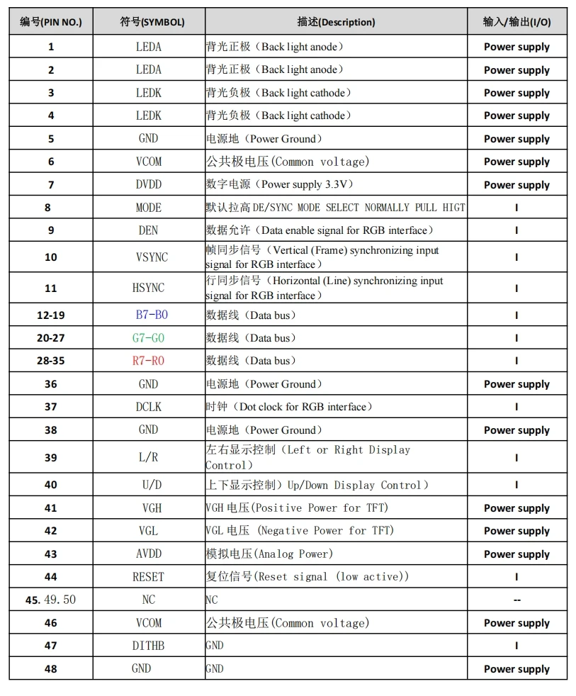 (click to embiggen)
can suffice. Then, the video timings you need to use for the display are usually the standard
Coordinated Video Timings, Reduced Blanking (CVT-R); hopefully per
CEA-861-I. There are online calculators for this. Or, you can test if the ones in similar displays' datasheets work.
Without a datasheet or pinout,
I would not bother. Yes, there are lots of very nice cheap displays at AliExpress without datasheets, especially as replacements for car displays and tablets and even handheld consoles, but it is a LOT of work to reverse-engineer the pinout, and it usually involves the destructive deconstruction of at least one unit, likely more during testing.

 Home
Home Help
Help Search
 Login
Login Register


