Making send_serial_byte() even more usefulNow that our SoftUART can send data to a PC we already have the basis of a very useful debugging function. If you sprinkle the code you are trying to debug with with send_serial_byte() function calls, you can use RealTerm to track and know exactly where your code is executing as it goes.
You will notice that RealTerm has a useful capture Tab. When testing code that may only execute a certain function infrequently, or that you need to see working over a period of a Day or more, you can set RealTerm to capture any bytes sent by your Microcontroller and save them to a file. You can even set up the length of time to capture for or the maximum number of bytes. Coupled with the SoftUART, even as it stands with only the Send functionality, you have a tool that is perfect for debugging Home Automation or Data Logging type applications.
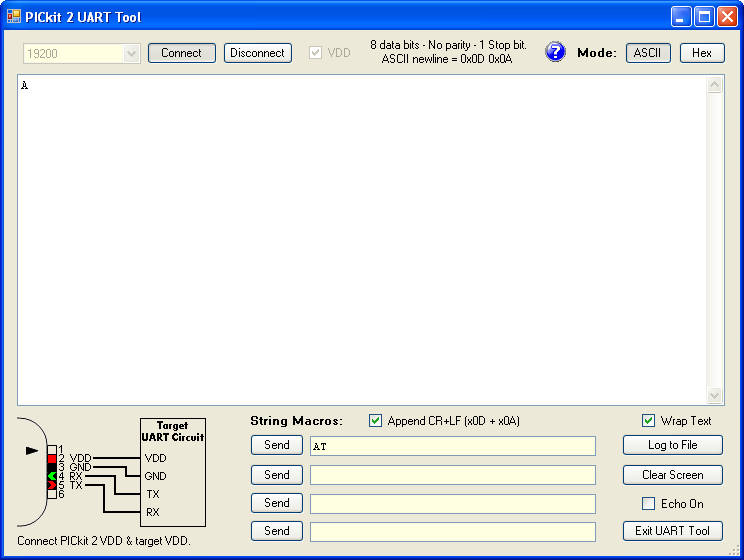
Not all PC’s, however, have RS232 Ports these days and I have not tested this code with an RS232 to USB adapter cable (it should work though) so for those situations it would be nice to have the SoftUART able to send data to our PICkit UART Tool (which can also capture to a file) or to RealTerm via an FTDI or MAX232 chip.If you close the Logic Tool and open the UART tool as it stands, you will see nothing displayed. That is because the send_serial_byte() function is using negative or inverted logic. The reason for this is that a MAX232 or equivalent circuit normally performs the signal inversion at the same time as it converts the voltage levels to RS232. Take a look at the schematic of a MAX232 chip and you will see why:
 What we need to do then is provide an option to have our code run either Normal or Inverted Logic Signals. Not only will this give us the flexibility needed to talk to different devices with different requirement, it will actually give us one up on the Hardware UARTs built into many Microcontrollers as they are not capable of providing the inverted signals at all.
We will begin by defining a new constant that represents the Logic Level to use:
#define SER_BIT 0 // Signal MODE - 1 = Normal 0 = Inverted (Use Inverted for direct 232)
We also need a new line of code in our setup, because we have been using negative logic it didn't matter that the Tx Pin was sitting in the default low state, as that is the correct Idle State with negative logic. But if we wish to use positive logic, we need to pull that line high when we are not sending. This will take care of it:
PIN_SER_OUT = SER_BIT;
Then in our send_serial_byte() function we replace every occurrence of an explicit Bit State with our Constant. That way just by changing the one line of code at compile time we can invert the Logic of the entire Function. Four lines need to change:
PIN_SER_OUT = !SER_BIT; // make start bit
The Start bit is always the opposite of the Idle level so it is proceeded with a ! (NOT), and our two lines that send the actual data become:
if(data & 1<<0) PIN_SER_OUT = SER_BIT; // send data bit
else PIN_SER_OUT = !SER_BIT;
Finally we need to send a Stop Bit:
PIN_SER_OUT = SER_BIT; // make stop bit
In order to test it, however, we need to change our Test Character. the 'U' will be the same in both Positive and Negative logic, so change the test character to 'A'.
Our code the will look like this:
//____________________________________________________
//
//   Soft UART Test for PIC16f690
//   Based on http://www.romanblack.com/bitbangserial.htm
//
//   C.A.Roper - 2013/02/26
//____________________________________________________


#include <xc.h>
#include <stdint.h>
//
// Configuration Fuses
//
#pragma config   FOSC   = INTRCIO      // Internal RC Osc 4Mhz I/O function on RA4 & RA5
#pragma config   MCLRE   = ON         // RA3 NOT avalable for input
#pragma config   CP      = OFF         // Code Protection Off
#pragma config   CPD      = OFF         // Data Protection Off
#pragma config   WDTE   = OFF         // Watchdog Timer Disabled
#pragma config   BOREN   = OFF         // Brownout Detection Disabled
#pragma config   PWRTE   = OFF         // Power-up Timer
//
// Prototypes of functions used
//
void send_serial_byte(unsigned char);
//
//   Global Defines
//
// #define PIN_SER_OUT LATA.F3          // which pin for serial out (PORTA.F3)
#define PIN_SER_OUT PORTAbits.RA0       // which pin for serial out (PORTAbits.RA1)
#define SER_BAUD 51                     // TMR1 (1Mhz/19200 baud) = 52
#define SER_BIT         0             // Signal MODE - 1 = Normal 0 = Inverted (Use Inverted for direct 232)
//
//   MAIN
//
void main(void)
{
//
//   Setup - Run once
//
   //   Default I/O Setup
   //
   ANSEL             = 0;            // Disable Analog
   PORTA            = 0;            // Turn all Outputs OFF
   TRISA            = 0b001010;         // INPUTS: RA1 = RxPin, RA3 = Button
   T1CONbits.TMR1ON   = 1;            // Activate Timer 1

   PIN_SER_OUT         = SER_BIT;


   send_serial_byte('A');
//
//   Main Loop - Run Forever
//
   while(1)
   {
      ;
   }
}


//
//   User Functions
//


//---------------------------------------------------------
void send_serial_byte(unsigned char data)
{
  // this manually sends a serial byte out any PIC pin.
  // NOTE! serial is inverted to connect direct to PC serial port.
  // baud timing is done by using TMR1L and removing
  // timer error after each baud.
  unsigned char i;


  i=8;                            // 8 data bits to send


  PIN_SER_OUT = !SER_BIT;         // make start bit
  TMR1L = (256 - SER_BAUD);       // load TMR1 value for first baud;
  while(TMR1L & 1<<7);                // wait for baud


  while(i)                        // send 8 serial bits, LSB first
  {
    if(data & 1<<0) PIN_SER_OUT = SER_BIT;  // send data bit
    else    PIN_SER_OUT = !SER_BIT;


    data = (data >> 1);           // rotate right to get next bit
    i--;
    TMR1L -= SER_BAUD;            // load corrected baud value
    while(TMR1L & 1<<7);              // wait for baud
  }


  PIN_SER_OUT = SER_BIT;          // make stop bit

  TMR1L -= SER_BAUD;              // wait a couple of baud for safety
  while(TMR1L & 1<<7);
  TMR1L -= SER_BAUD;
  while(TMR1L & 1<<7);
}
//---------------------------------------------------------
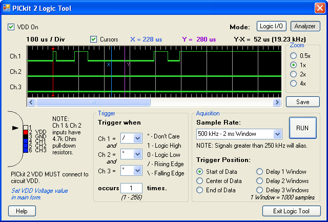
Switch back to the Logic Tool and press the Reset Button to capture the new waveform. If you still have RealTerm running you should see an 'A' displayed there too. My waveform looks like this:
 Now Change the SER_BIT Constant to a 1 and recompile it.You should capture a waveform like this:

Now switch to the UART Tool, Select 19200 as the speed and click Connect.
Press the Reset button and you should get an 'A' displayed.

You now have a Software UART that can send debug messages to either your PC, with or without a MAX232 or FTDI Chip, or directly to the PICkit2 UART Tool.
Your Debugging Tool Kit has just been expanded, and I think you will find it to be the most useful debugging Tool you ever had for the Midrange PICs and it enhances your investment in the PICkit2 as well.
That is it for now and, apparently, I will have no power for the entire day tomorrow, so don't expect any updates for the Next 24 Hours.
When we continue we will be looking at implementing the receive_serial_byte() function.
Until then I will be sitting in the Sunshine, Reading an Electronics Magazine or two and drinking a couple of cold beers

Enjoy your Wednesday everyone, I know I will enjoy mine out here in "Darkest Africa".
Cheers
Chris