-
Nice, I must give this a try. Between work and the whole Covid mess I got sidetracked and have not had a chance to mess with this lately.
-
Nice, I must give this a try. Between work and the whole Covid mess I got sidetracked and have not had a chance to mess with this lately.
James, your TDS-420, I think, will still require the interface to be set in LON mode with '++lon 1' before starting the 7470 program. I will be very interested to know how you get on with the update as and when you get a chance to try it.
-
Have just uploaded version 0.48.22, which now includes support for the Leonardo R3 board. The board itself has a near identical layout to the Uno and the sketch employs the same pinout. The board has a micro USB connector instead of the larger type of USB connector. It also has some advantages:
- it uses CDC serial ports, does not employ the CH340 chip for USB communications, so does not require any modification in order to work with the KE5FX toolkit
- has slightly more runtime memory (2.5kb vs 2kb)
- serial port 'serial1' is a separate hardware port and does not interact with USB communications
-
Thanks for all the work you guys are putting into this project. Since this thread started with just a couple of the full size uno and mega boards and has now evolved into multiple variants of micro, mini, esp, rasberry, etc... is there a simple way of adding a document on the github or on 1st page of topic with maybe excel tables with which version arduino, wifi/bluetooth/ethernet support/ and maybe verified equipment that has been tested working. Bonus points for rounding up different pcb adapter links that have been used so there could be easier way to have someone like myself say well I have a few V3 nanos but want bluetooth connectivity to x multimeter and x o-scope. Would be cool to see what members have already tested sucessfully and would let those thinking about building up the ar488 see if a different version board would be a better option. If this sounds like it should be on a seperate forum topic please chime in.
To summarise then:MCU Board Serial Ports Layouts 328p Uno R3 Single UART shared with USB Layout as per original project by Emanuelle Girlando 328p Nano USB/Single UART shared with USB Identical to Uno 32u4 Micro USB/CDC+1 UART Compact layout by Artag, designed for his back-of-IEEE488-plug adapter board 32u4 Leonardo R3 USB/CDC+1 UART Identical to UNO 2560 Mega 2560 4 x UART, Serial0 shared with USB D - default using pins to either side of board
E1 using first row of end connector
E2 - using second row of end connectorESP32 Various 3 x UART, U0UXD/Serial0 shared with USB In development
The 32u4 and mega 2560 boards will work with the ESP8266 WiFi add-on and the HC05 bluetooth module. The HC06 module can also be used but has to be programmed manually. Using these on the Uno or Nano is not advised as the only available serial UART is used by USB. One may run into problems having both connected at the same time. One could however, use SoftwareSerial at a speed of no more than 57600 baud..
Further work in planned for the ESP8266 and an ESP32 version is in development. Adding an Ethernet shield (to the Mega 2560) is also planned.
I am not aware of a version for the Raspberry Pi but would certainly be interested to know if such a thing exists and where you saw it? It certainly has plenty of GPIO pins but costs a little more.
Much of this information is already in the readme, however I can certainly add/convert in tabular form if it helps.
-
That was very helpful, thanks. Had my hopes up to try my hand at building a adapter board for nano that includes temp/humidity sensor as well as bluetooth but now see that it will have issues more than likely, thanks for that info.
As far as the Ras-Pi info I see it hasn't been updated in years but probably best documented link is from from Xdevs https://xdevs.com/guide/ni_gpib_rpi/
Another good source for schematic and instruction http://elektronomikon.org/
There is also similar project that started as Pi then converted to arduino due to popularity and cost http://www.industrialberry.com/gpiberry-v1-1/
-
I haven't had a chance to try the TDS400 but I had to do something with a TDS700 already so I tried plotting from it. I can confirm that once I sent a ++lon and then loaded up the plotter emulator I was able to hit Hardcopy and it plots perfectly.
So do we know at this point whether the need to send ++lon is a bug in the GPIB interface or in the 7470A emulator?
Thanks. I am glad that you can now send a plot to the HP7470. This appears to confirm that ++lon is necessary for Hardcopy to work on a Tek then.
I'm not sure that the need to send ++lon should be characterised as a bug. It simply places the interface in the required operating mode. Looking at the manual, the TDS-700, like the TDS-400, operates in non-addressed or talk-only mode. In order to receive, the "plotter" would need to be in the corresponding non-addressed listen-only mode. This is what the ++lon command does. This kind of direct point-to-point communication makes sense in a 1:1 scenario where you have a plotter connected directly to the back of an instrument with the instrument pushing data over the GPIB wires to the plotter.
However, if the interface is connected to a GPIB bus that connects multiple devices and just accepts all data, then it will end up passing all information being sent to and from those devices to USB. Addressed mode, where each interface is assigned a unique GPIB address allows the interface to accept only data that is intended for it, that is, when it has been addressed by a controller to listen. The HP 8591A spectrum analyser instrument operates in that mode and can therefore co-exist with other instruments on the bus.
Just how the Prologix operates in both circumstances is something I would like to establish. Whether that behaviour is "proper" or rather a pragmatic approach bearing in mind possible usage scenarios is also something I am curious about. If someone has a Prologix interface and some instrument, then it shouldn't be too difficult to establish this with the following tests:
- connect instrument to Prologix.
- configure the instrument with a plotter GPIB address.
- assign the Prologix a different GPIB address and place it in device mode
- connect to the Prologix with a terminal
- send a plot.
Is anything received? (there shouldn't be)
- connect instrument to Prologix.
- configure the instrument to use non-addressed (talk-only) mode (or use an instrument that employs this mode by default, e.g. Tektronix TDS-400 and later series)
- assign the Prologix a GPIB address and set it in device mode
- connect to the Prologix with a terminal
- send a plot.
Is anything received? (again, there shouldn't be)
In both cases we used Device mode but not ++lon. So finally, repeat the second example with instrument in talk-only mode, but additionally place the Prologix in ++lon mode. It should now receive.
I had been toying with the possibility of ordering a 164p chip (which the Prologix is based around) and flashing their firmware to it with an AVR programmer. The 40pin DIL version of the chip should fit the programmer I have for an AT16P. It does cost more than a complete Arduino board but still much cheaper than a Prologix. I might order one if that is the only option, but if anyone does have a Prologix and can perform these tests an post the results then it would be greatly appreciated.
Back in post #397, KE5FX mentioned he would be adding the option to send ++lon to an interface. No doubt he will let us know when that has been done.
-
Got it working with a Fluke 8840a

Sorry for missing your earlier comment and thank you for posting your photos. Interesting to see different instruments being connected. Curious that you didn't use an IEEE488 connector but soldered directly to the board inside the instrument. Are you intending to mount this internally somehow? I haven't tried those Elegoo boards so its good to see that they do also work.
-
I'm not sure that the need to send ++lon should be characterised as a bug. It simply places the interface in the required operating mode. Looking at the manual, the TDS-700, like the TDS-400, operates in non-addressed or talk-only mode. In order to receive, the "plotter" would need to be in the corresponding non-addressed listen-only mode. This is what the ++lon command does. This kind of direct point-to-point communication makes sense in a 1:1 scenario where you have a plotter connected directly to the back of an instrument with the instrument pushing data over the GPIB wires to the plotter.
Well it's a bug in one part or another, Hardcopy works just fine IF you first load up another program and issue the required command. It's looking to me like it's a bug in the plotter emulator, it should be sending ++lon if you set it to non-addressed mode and then have it listen for a device initiated plot.
If the option to send ++lon is added then I believe that will fix it. -
Got it working with a Fluke 8840a
Sorry for missing your earlier comment and thank you for posting your photos. Interesting to see different instruments being connected. Curious that you didn't use an IEEE488 connector but soldered directly to the board inside the instrument. Are you intending to mount this internally somehow? I haven't tried those Elegoo boards so its good to see that they do also work.
Remove gpib connector completely. Replace with a promicro on a small adapter board.
-
Curious. Why not just use Atrag's adapter?
https://www.eevblog.com/forum/projects/ar488-arduino-based-gpib-adapter/msg2718346/#msg2718346
-
Uploaded version 0.48.24. It is now possible to send debug messages to an alternative serial port e.g. Serial1 on 32u4 boards.
-
Hi,
I built the interface, worked first time with a UNO - brilliant.
As I couldn't find any old / low cost GPIB cables I used a short length cut from an old scart cable , over short lengths works fine maybe a useful tip for anyone else building the interface.
The interface is connected to my Solartron 7061 which performs logging using PuTTy or the arduino serial monitor
I am trying to read out the memory of the 7061. I can do this 1 memory location at a time but to do this automatically has exceeded my skill level :-)
For example:
Using the serial monitor (red is my typed command)
DU is the 7061 command to DUmp the memory contents
HIST is the memory location of the particular measurement being read back.
Hello from AR_SERIAL :-)
++Auto 2
++Read
-0.0000101 VDC CHAN 0
DU
++Read
-0.0000129 VDC CHAN 0 HIST 1
++Read
-0.0000133 VDC CHAN 0 HIST 2
++Read
-0.0000134 VDC CHAN 0 HIST 3
etc
Using this macro
#define MACRO_4 "\
++addr 1\n\
DU\
++auto 3\n\
++read\
returns -0.0000042 VDC CHAN 0 HIST 3 and Bad Argument on the meter
and using this modified macro
#define MACRO_4 "\
++addr 1\n\
DU\
++auto 2\n\
++read\
returns -0.0000054 VDC CHAN 0 HIST 2
Possibly a timing issue, but I'm now a bit stuck, any help greatly appreciated.
Dek
<edit>
If I reorder the macro to
++auto
DU
++Read
then it works
Also works if i enter the commands manually in that order via the serial monitor or PuTTy
-
I have used the AR488 controller on Arduino Nano to talk to many different devices without any problem. But one recently stumped me. Its a Cryocon temperature controller that uses EOI but no EOS characters. I have set the program for ++eoi 1 and ++eos 3 and it still didn't work. The device would switch to remote and then go back to local with ++loc command, so it was getting something. I also verified that EOI line was indeed asserted during the transmission. Crycon worked just fine with NI controller and VISA. Not sure what the problem was, has anyone used an instrument with these settings?
-
The interface is connected to my Solartron 7061 which performs logging using PuTTy or the arduino serial monitor
I am trying to read out the memory of the 7061. I can do this 1 memory location at a time but to do this automatically has exceeded my skill level :-)
For example:
Using the serial monitor (red is my typed command)
DU is the 7061 command to DUmp the memory contents
HIST is the memory location of the particular measurement being read back.
Hello from AR_SERIAL :-)
++Auto 2
++Read
-0.0000101 VDC CHAN 0
DU
++Read
-0.0000129 VDC CHAN 0 HIST 1
++Read
-0.0000133 VDC CHAN 0 HIST 2
++Read
-0.0000134 VDC CHAN 0 HIST 3
etc
Using this macro
#define MACRO_4 "\
++addr 1\n\
DU\
++auto 3\n\
++read\
returns -0.0000042 VDC CHAN 0 HIST 3 and Bad Argument on the meter
and using this modified macro
#define MACRO_4 "\
++addr 1\n\
DU\
++auto 2\n\
++read\
returns -0.0000054 VDC CHAN 0 HIST 2
Possibly a timing issue, but I'm now a bit stuck, any help greatly appreciated.
Dek
<edit>
If I reorder the macro to
++auto
DU
++Read
then it works
Also works if i enter the commands manually in that order via the serial monitor or PuTTy
My 7150 does not have the DU command so I can't test that specific command, but I do have a couple of observations. Firstly, could I ask which firmware version are you using please?QuoteHello from AR_SERIAL :-)
That is spurious and shouldn't be in the output. It must have been accidentally left in one of the versions. By all means find the relevant line in AR488.ino that is printing it and either remove it or comment it out.
In your macro, the DU command and the last ++read do not have a \n after it. Can you clarify whether this is a typo in the post or whether you have actually entered the macro in that way? You can get away without having a \n at the end of the macro, but it is essential that one exists as a delimiter at the end of on every other line. So your two macro's should read:
1st example:Code: [Select]#define MACRO_4 "\
++addr 1\n\
DU\n\
++auto 3\n\
++read\
"
2nd example:Code: [Select]#define MACRO_4 "\
++addr 1\n\
DU\n\
++auto 2\n\
++read\
"
When auto is set to 2, it looks for instrument commands terminated with a query '?' character, e.g. *idn? and automatically performs a ++read afterwards to return the query result. If a '?' is not present, then it just sends the character string and does nothing else. Setting auto to 2 would have no effect in this instance. This is different to ++auto 1 which will always try to return a result after any command string sent to the instrument.
How many memory locations are there and what result are you expecting to see?
-
I have used the AR488 controller on Arduino Nano to talk to many different devices without any problem. But one recently stumped me. Its a Cryocon temperature controller that uses EOI but no EOS characters. I have set the program for ++eoi 1 and ++eos 3 and it still didn't work. The device would switch to remote and then go back to local with ++loc command, so it was getting something. I also verified that EOI line was indeed asserted during the transmission. Crycon worked just fine with NI controller and VISA. Not sure what the problem was, has anyone used an instrument with these settings?
Interesting since CryoCon seem to provide a Prologix Ethernet interface as an option. I note from their manual that the instrument uses the SCPI language with ; as terminator although this is optional. While the User Manual states that "the host must be configured to talk to the instrument using EOI and no EOS", the remote Programming Guide states that "if terminators are sent they are ignored" so one assumes that they shouldn't be an issue, but it is understandable that the User Manual recommends to eliminate them altogether with ++eos 3. Are you getting any output at all in response to e.g. *idn? or nothing at all? It seems that aside from setting the GPIB address, there is not much else to do here and the fact that it responds to ++loc would seem to indicate that the instrument is receiving addressed commands. If possible, a DEBUG7 output or a logic analyser trace might provide some useful information.
-
I wasn't able to get any response from Cryocon beyond seeing the remote light go on and off. I played with various eos and also eor options to no effect. I checked with a scope that EOI line was going low. What I haven't done is to hook up a logic analyzer to several lines to look at relative timing. Perhaps the issue is the timing of the EOI line relative to the end of transmission. The instrument is now back in the lab working over NI interface. I was just debugging it at home. In general, AR488 is great at allowing one to work from home without installing the whole Labview suite.
-
If anyone wants to copy the version I built, you can get PCBs from here : https://oshpark.com/shared_projects/HrS1HLSE
I will probably revise that at some point (I'd like to move the daughterboard further along, making the USB connector stick out less) but don't know how long I'll take to get around to that. The electrical connections will stay the same so the software will still work.
Many thanks for making your PCB design available on OSHPark. I ordered six PCBs and received eight so even after building one interface for each of my GPIB equipped instruments, I'll have a couple of spares on hand for when the next device arrives.
Putting everything on the plug and not having to deal with bulky, stiff GPIB cables is brilliant! Even better, I'll be able to connect all of the instruments to a powered USB hub and have everything available via one USB cable to my computer. Priceless.
I chose to bolt mine together for better rigidity. I did the first one with some screws from a old laptop's VGA port and needed to mount the Arduino fairly high on the pins to ensure I could connect to the USB connector. Hopefully, I'll have some button head UNC 4/40 1/4" screws on the way soon for the remaining adapters.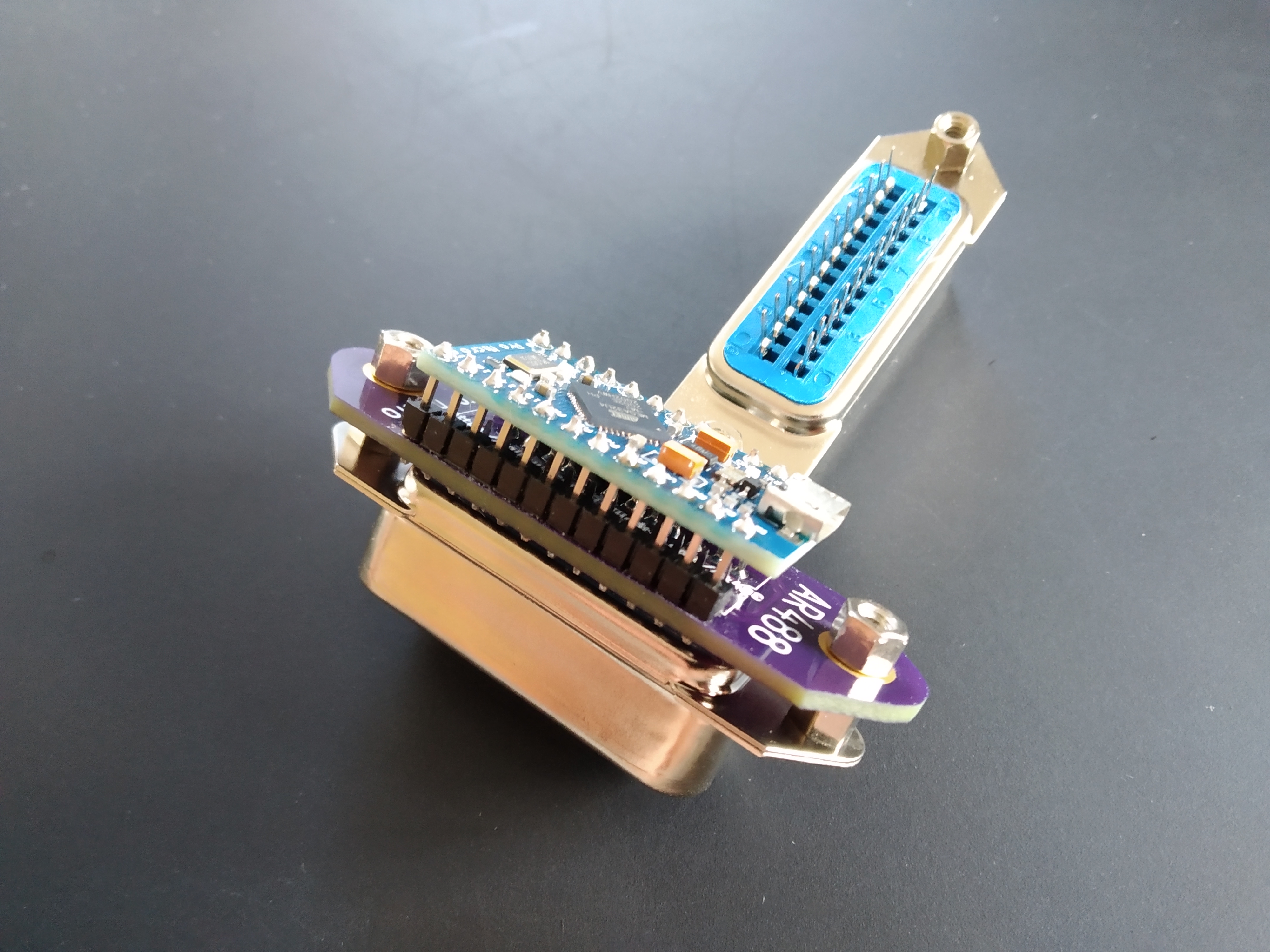
-
Those tiny adapters from artag are amazing! I have a question. If each instrument has its own adapter and they all connect to a USB hub instead of being on a GPIB cable bus, how do you address and use multiple instruments at once? I use python to talk to the one, master, AR488 and then the GPIB address to control specific instruments. I would love to swap out the GPIB cables for USB!
-
You use the serial port to select the instrument. You can set all the GPIB addresses the same as there is only one on each bus.
-
You use the serial port to select the instrument. You can set all the GPIB addresses the same as there is only one on each bus.
Side question, is it still possible to have multiple devices (with unique addresses) on the same gpib bus with one ar488? -
Side question, is it still possible to have multiple devices (with unique addresses) on the same gpib bus with one ar488?
Yes, it is, though you do have to send the ++addr command to address each one : if you only use one per instrument then it can be configured to always address that device, so it's as though it's connected to a USB serial port.
Rather than use the same address for each, I prefer to use the default address for that instrument. Most modern instruments have the address defined in non-volatile ram and a default value is set at manufacture.
The electrical specs don't fully meet the IEEE-488 requirements so it won't drive 16 instruments under worst case conditions. However it seems fine at 5 and may well manage more.
If you use Linux then the appropriate serial port can be addressed meaningfully through /dev/serial/by-path. I'm not sure if Windows' persistent COM port association will see them as different.
I would like to be able to set the ID (and hence the location in /dev/serial/by-id) to suit the attached instrument but the arduino lib used doesn't currently permit it. That might get fixed at some point.
-
Well it's a bug in one part or another, Hardcopy works just fine IF you first load up another program and issue the required command. It's looking to me like it's a bug in the plotter emulator, it should be sending ++lon if you set it to non-addressed mode and then have it listen for a device initiated plot.
If the option to send ++lon is added then I believe that will fix it.
I agree with WaveyDipole - the plotter emulator needs to have its interface set to listen-only but on a real plotter that would be done with a DIP switch.
I haven't checked it recently but I think you can manually send ++lon and then save the ar488 config, causing it to reset into lon mode on every power up. Does this work ?
-
Back on 18th March in post #397 KE5FX did say he would add that feature. On his website I can see that the toolset was updated on 20th March (v1980) and again on the 26th March (v1981). I downloaded it to have a look, but could not see the ++lon feature implemented it yet so we will have to wait until the next release I think.