When developing anything that flies,
telemetry is important. If your test vehicle suddenly takes a nosedive into the ground, you'll want an external record of speed, control surface positions & commands, engine status, etc. so there's some hope of figuring out why. I was lucky to find this Hughes Aircraft telemetry unit from the late 60's: everything in here could be implemented in $20 worth of parts from Digi-Key today, but it's a goldmine of fascinating historical electronics.
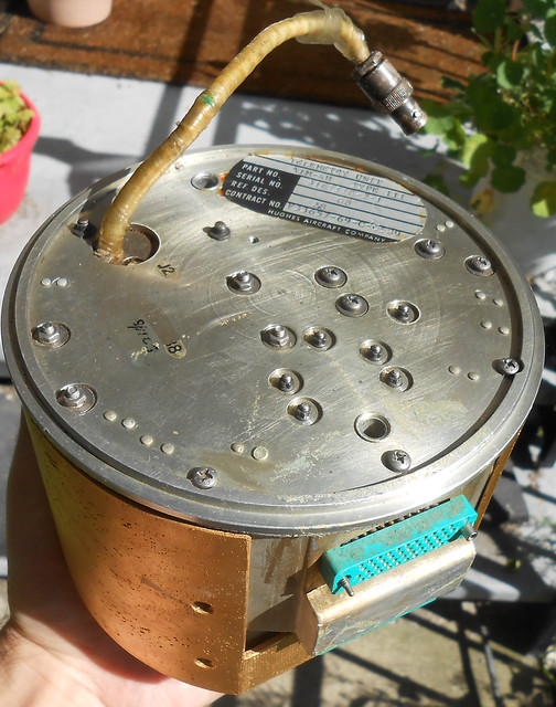


The "AIM-4H" referenced on the label seems to be an
old missile variant that never left development (scroll up a few lines). Considering how many different projects Hughes Aircraft was running, though, I'd be surprised if this wasn't a fairly general-purpose unit. This was also not something that would be used on an "in-service" missile - no need to have it broadcasting unnecessary data and announcing its presence. So just to forestall some uninformed "you're giving away military secrets!" responses and be clear about the context: this was a
prototyping tool from over half a century ago, which any EE student could build now with parts from a Radio Shack if they still existed. That's not to diminish the amount of work that went into this, though - it's full of cutting-edge miniaturization for the time, like op-amp ICs and switch-mode power supplies.


Looking inside, we can see a variety of different parts:
 1. Battery & Power Supply

The telemetry unit gets its own internal power (in case the external power fails, I assume) from a
thermal battery. From a little bit of reading, these seem to have a small amount of fuel inside which burns in a controlled way when activated, producing heat and melting an electrolyte which enables electron exchange to start happening. (This is different than the
RTGs used in spacecraft, but as in addition to radioactive decay as the heat source, those use
thermoelectric generators - same principle as thermocouples.) The run time sounds like it's short but they are apparently very stable in storage (inert until triggered, so none of the self-discharge of a normal electro-chemical battery), so they were popular for some niche applications like this one where something has to sit for a long time, and then work reliably.
The output from the battery is passed on to the internal power supply:


This looks like a switch-mode power supply, which uses a transformer on the back side and several stud-mount power devices. From the single battery input, it generates at least 1 digital-logic voltage, and a set of positive & negative analog supplies.
With the way it's put together I couldn't map out the circuitry in the power supply, but my best guess is that there's
some kind of simple self-oscillating circuit like a resonant Royer oscillator driving the transformer's primary winding; multiple secondary windings are then separately rectified and provide the different output voltages. There's probably linear post-regulation on each of these output voltages, as a multi-output supply can only keep one output regulated by controlling the switch timing. The larger board in the front has a lot of tantalum capacitors and diodes, which are likely the rectification and bulk storage for the output voltages. Counting the stud-mount devices, there's 5 transistors and 1 diode, which is enough for 2 switching transistors and 3 linear regulators.
2. Input signal conditioningThe signals to be monitored all enter on the two external connectors.

They're then fed by a complicated but very neat wiring harness to these 3 boards at one edge, that all provide scaling and input protection for the external inputs.


Starting from the outside-most board...


If you look carefully here, you can see multiple channels - not perfectly identical, but with common themes. Each one has a series & shunt resistor (protection and pull-down, plus a voltage divider), sometimes a filter capacitor or two, and a pair of diodes that clamp the signal between 0V and the supply voltage of the data encoder (which we'll be looking at later).

The other boards contain more circuitry:


There's small metal cans labeled "SL7160"...


...and a larger wide, flat metal can labeled 2809BG-003:


I couldn't find anything matching these part numbers, so I cut open one of each can.
The smaller one contains a simple op-amp:


The larger one contains a hybrid circuit, with an op-amp, 2 JFETs, and a resistor network:


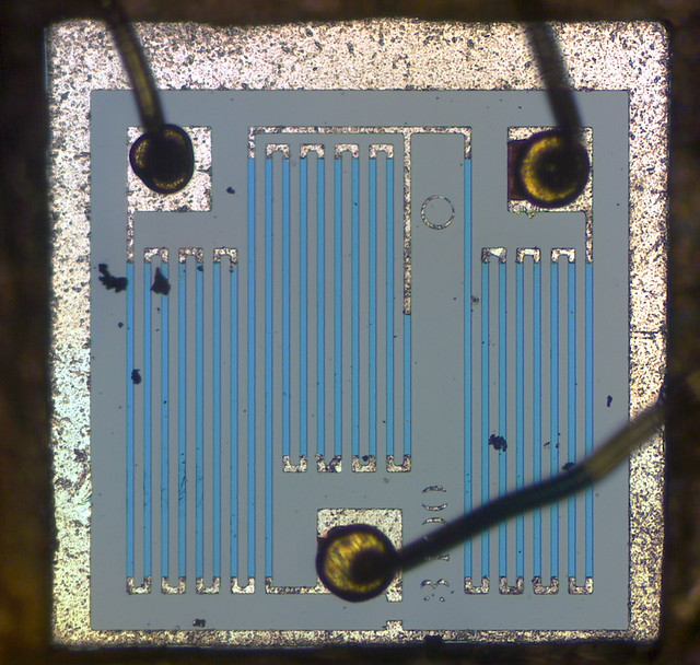
The JFETs & resistor network form a high-input-impedance differential buffer stage which buffers the positive and negative inputs before they reach the op-amp. By about a decade later you could buy single-chip op-amps with JFET inputs such as the
TL08x to achieve these high input impedances, but when this was built these weren't yet available, and so taking a custom-packaged hybrid-module approach made the most sense.
I mapped out a couple of representative op-amp channels - they're all pretty much identical, maybe with different resistor values:

The top one uses the large-metal-can hybrid and larger input resistor values (no bad effects with the JFETs' almost-zero input bias currents). However, they both perform the same function of: (1) receiving a differential input from the external connectors (a sensor or status output of some kind), (2) applying scaling to it, and (3) doing a differential-to-single-ended conversion to remove any common-mode noise picked up on the wiring. There's also a positive offset added by R9/R10 & R13/R15: I'm guessing this is to make a bipolar signal fit the positive-only 0-to-VAA input range of the data encoder.
3. Data encodingNext comes the real "meat" of the telemetry unit - the so-called "multicoder", which does the multiplexing and modulation.


This is a separate unit made by a different company, which I couldn't find any info on. It does the main work of cycling through each input channel one by one, creating a properly timed and modulated output signal to represent the state of each input in turn. That modulation could be digital (pulse-position, pulse-width...) or analog (frequency, phase, amplitude...). I'll look inside this box in the next post, but for now know that it takes 32 analog inputs and produces a single time-multiplexed output. You also might be able to see from the wiring that many of the input channels are redundant - apparently not all 32 channels were needed, so all the unused channel inputs (almost half) are connected as duplicates of other inputs.
4. VCOs & Radio transmitterThis data now has to be sent to an antenna somehow. The first photos of the outside of the telemetry unit showed a flying BNC cable, and that comes back to this stack of electronics next to the multicoder and battery:

At the top of the stack are a couple boards, which contain 2 channels of additional input-signal-conditioning circuitry. I guess there wasn't room on the other signal-conditioning boards and so the extra circuitry had to be crammed in here.


Below these are 3 miniature VCO modules - some cute tiny little guys. We'll be looking inside one of these in a future post too.

Finally, at the bottom of the stack is the radio transmitter itself. This holds the RF oscillator, final modulator, and power amplifier all in one.

According to the label, using it is pretty simple - it only needs 3 connections, for power, ground, and modulation input. The antenna output is on the fixed coax cable that extends from the telemetry unit. Don't worry, we'll also be looking inside this module as well.
5. Overall setup & connectionsSo, now we've seen the general overview of how signals enter, are scaled and/or offset, are muxed/encoded by the data encoder, and then are somehow fed to the radio transmitter. But what are the details? Why are there 3 separate VCOs above the radio transmitter?
Tracing the circuitry on the two boards at the top of the radio-transmitter stack, the overall picture becomes clearer:

The top section is just another mostly-normal channel of signal conditioning, although single-ended for some reason. Ignore that part.
Notice how the 3 VCO outputs are connected together, and then connected to the radio transmitter's input: it looks like they must have finite output impedances, and are getting summed. The "set" wire from each VCO is also connected to a different-value resistor: these must be the center-frequency-adjustment connections.
So, we have 3 separate
sub-carriers being transmitted on the radio channel. One of these sub-carriers is modulated by the multicoder, and so contains the majority of the telemetry channels, time-multiplexed (VCO 3). A 2nd sub-carrier is modulated directly by one of the signal-conditioning channels (VCO 2), and the 3rd sub-carrier is modulated directly by the circuitry in the middle of the schematic (VCO 1). VCO 1's channel seems to be a sum of 3 different external inputs.
Why the 3 sub-carriers? Why not feed these 2 additional channels to the multicoder and have them muxed along with the rest of the channels? The benefit of having these 2 channels on their own separate sub-carriers is that their readout is continuous: you don't have to wait through the full muxing period of the multicoder to get a glimpse of their value. These are probably higher-bandwidth signals like control loop outputs, then, rather than slow-changing DC values like temperature or battery voltage.
Next I'll be showing off the inside of the multicoder module.

 Home
 Help
 Search
 Login
 Register


