Author Topic: Different die pictures  (Read 87086 times)

0 Members and 1 Guest are viewing this topic.

Online mawyatt

  • Super Contributor
  • ***
  • Posts: 3274
  • Country: us
Re: Different die pictures
« Reply #225 on: August 26, 2022, 05:02:44 pm »
Hi!

I just took some images of a DRV8302 with the keyence microscope because i was puzzled why i could just not see anything under my sem.
Really interesting Ti seems to do this not only on high end stuff but ob sort of regular components.

The passivation under the masking layer seems to be something like 5-10um, maybe it can be polished off.

These look like "Fill Patterns" common in many processes where they help keep the layers planer during fabrication by maintaining a minimum metal density across the chip.

Best,
Curiosity killed the cat, also depleted my wallet!
~Wyatt Labs by Mike~
 

Online magic

  • Super Contributor
  • ***
  • Posts: 6783
  • Country: pl
Re: Different die pictures
« Reply #226 on: August 26, 2022, 08:31:28 pm »
I just took some images of a DRV8302 with the keyence microscope
Those pics don't look bad at all :-+
What sort of scope, exactly? I see they make digital microscopes, they surely must be better than those from eBay.
 

Offline Amper

  • Frequent Contributor
  • **
  • Posts: 286
  • Country: 00
Re: Different die pictures
« Reply #227 on: August 27, 2022, 07:43:14 am »
@mawyatt: You may be right but i wonder why its used here. Usually fill patterns are used on lower layers or in chemical processes. In PVD its not really of interest and even on power devices with very thick metalizations i have never seen fill patterns before.

@magic: Its a Keyence VHX7000, not really in reach for any hobbyist i guess but we have one at work that i can use as long as i dont break anything :) Taking good looking images is VERY easy with modern microscopes.
 

Online magic

  • Super Contributor
  • ***
  • Posts: 6783
  • Country: pl
Re: Different die pictures
« Reply #228 on: August 27, 2022, 08:07:01 am »
Thanks, although they don't show specs that would permit comparison against other microscopes and I would need to register to download the datasheets, still without guarantee that there is any useful information there ::)

But it resolves 0.6µ wide traces with 0.6µ gaps fairly sharply, this is close to the limits of visible light microscopy in dry air.

BTW, if you forego all the automation, there is plenty of moderately priced metallographic scopes which can do the same if fitted with a camera and high power objectives. I think it would take some 40x0.65 at a minimum. I'm experimenting with adding reflected light illumination to a cheap biological scope, but contrast is not the same as in purpose-made optics and the objectives are annoyingly corrected for use with cover glass.
« Last Edit: August 27, 2022, 08:13:46 am by magic »
 

Offline Amper

  • Frequent Contributor
  • **
  • Posts: 286
  • Country: 00
Re: Different die pictures
« Reply #229 on: August 27, 2022, 08:16:21 am »
Yes, unless you are in the position to spend up to 150k$ on a device those companies really suck support wise...

In fact yes, it is at the limit of what optical microscopy can do while not even being built mechanically strong, there is a lot of stuff done in software for image stabilization, essentially you have to find a rough focus, hit auto focus or 3D map and the microscope will do the rest. Setting up the light is pressing a button, the microscope takes several images in several configurations and you just pick the one that looks best. Its pretty idiot proof...

At home i have my JEOL6300, which im happy with unless there is thick passivations and i actually have to go optical.
 

Online NoopyTopic starter

  • Super Contributor
  • ***
  • Posts: 1737
  • Country: de
    • Richis-Lab
Re: Different die pictures
« Reply #230 on: September 06, 2022, 07:26:19 pm »
I have generated an area for quartz, oscillator and similar parts:

https://www.richis-lab.de/osc.htm


By the way: Now I know what the strange part under the quartz of the u-blox SARA modem is!


Thats a NTC to check the temperature! Now the laser tuning makes sense. Laser tuning a capacitor would have been quite strange.  ;D
I found a hint in the Qualcomm specification "GPS Quality, 19.2 MHz, Crystal, and TH+Xtal".

https://www.richis-lab.de/modem01.htm#GPS-OSC


The now one is a MCO1610A built by the Tele Quarz Group. The housing is called "1/2 dual-in-line". The A indicates the better variant with an accuracy of +/-50ppm. 32M most likely stands for a frequency of 32MHz.


In the case there is a quartz disk metallized on both sides. The pictures above are from two components, which is why the upper metallization is attached once on the right and once on the left.


The quartz disk is 0,15mm thick. The laterally arranged metal elements to which the quartz disk is soldered serve as fastening and as an electrical contact.


Under the quartz disk there is a ceramic carrier with a very simple circuit. Apart from a capacitor in the supply a SOT-23 component with the marking AP1 was sufficient. Further information about this component cannot be found.  :-//


The die of the AP1 is 0,97mm x 0,63mm. Some circuit parts can be identified. At the Vdd bondpad the larger structure probably serves to protect the circuit against surges. Protective structures can be seen at Y1, Y2 and Enable too.

A push-pull output stage is integrated on the left and above the clock output in the lower right corner of the die. The larger structure on the left of the Y1 bond pad could be used to excite the crystal.

Below the Y1 and Vdd bondpads are many small vertical lines, some of whose potentials were routed to this area with quite some effort. It could be that an alignment or a configuration with a laser took place at this point.


https://www.richis-lab.de/osc_02.htm

 :-/O
 
The following users thanked this post: SeanB, RoGeorge

Online magic

  • Super Contributor
  • ***
  • Posts: 6783
  • Country: pl
Re: Different die pictures
« Reply #231 on: September 06, 2022, 08:58:59 pm »
There similar chips like 74LVC1GX04, but other pinout and no enable.

I recall that NJM made some crystal drivers too, but I can't find the part numbers now. I don't even remember where I have seen those chips, could it be on Mouser? :-//

Is it sigma in those markings? :o
 

Online NoopyTopic starter

  • Super Contributor
  • ***
  • Posts: 1737
  • Country: de
    • Richis-Lab
Re: Different die pictures
« Reply #232 on: September 06, 2022, 09:02:59 pm »
There similar chips like 74LVC1GX04, but other pinout and no enable.

I recall that NJM made some crystal drivers too, but I can't find the part numbers now. I don't even remember where I have seen those chips, could it be on Mouser? :-//

Is it sigma in those markings? :o


It´s interesting that this one we have here needs no additional capacitor besides the supply capacitor.

Yes, that´s a sigma!  ;D

Online NoopyTopic starter

  • Super Contributor
  • ***
  • Posts: 1737
  • Country: de
    • Richis-Lab
Re: Different die pictures
« Reply #233 on: September 08, 2022, 08:30:08 pm »
Another new area is "various CPUs":

https://www.richis-lab.de/cpu.htm


The Motorola XC68060 is the last development stage of the 68000 family. The letters XC show that the device was not yet fully qualified. The fully qualified processors were later given the name MC68060. In addition to the XC68060 the XC68LC060 without FPU ("floating point unit", coprocessor) and the XC68EC060 without FPU and MMU (memory management unit) could be purchased. According to the data found in the "68K and ColdFire® - Product Portfolio - Overview - 3Q97" at least the first revisions of all three variants include both an FPU and an MMU. It is quite possible that one wanted to increase the yield with the deactivation of FPU and MMU.

Another advantage of the functionally reduced variants is the reduced power dissipation. The maximum clock for the XC68060 is generally documented as 66MHz in the "68K and ColdFire® - Product Portfolio - Overview - 3Q97". However, the XC68060 and XC68LC060 are only available with a clock  of 50MHz. Only the XC68EC060 can be purchased as a 66MHz version. The maximum possible clock is found behind the RC abbreviation, here RC50. Later variants officially allowed 66MHz for the 68080 and 75MHz for the 68EC080 and 68LC060.


The label in the upper right corner of the package contains the datecode 9706. The string 01G65V reveals the revision of the chip. In the document "68K and ColdFire® - Product Portfolio - Overview - 3Q97" Motorola just lists the first three revisions. The first revision is from 1993, and the XC qualification was done in 1995. www.amigawiki.org sorts this revision G65V behind revision 1F43G (https://www.amigawiki.org/doku.php?id=de:parts:68060_mask). The 01 before the G65V suggests with regard to the 0F43G and 1F43G revisions that the original G65V mask set had to be adjusted once.


The PCN 4460-68060 mentions the revision G65V. The PCN (Product Change Notification) informs that as of June 4, 1999 the G65V mask set will be replaced by the E41J mask set and thus the designation will also be changed from XC to MC. Consequently 4 years have passed until the fully qualified MC68060 emerged from the XC prerelease.


The PGA package offers 206 pins.


According to the "68K and ColdFire® - Product Portfolio - Overview - 3Q97" the size of the die is "582 x 579". Assuming that the unit is mil this is 14.78mm x 14.71mm. There are 2,530,000 transistors integrated on the die.

The two-stage contact frame has a surprisingly complex structure and offers 206 contacts connected with 209 bondpads.


The functions of the individual areas can no longer be easily assigned. One can just infer the function blocks on the basis of the shapes and structures.


The designation 68060 can be found on the die as well as the mask revision G65V. The design dates back to 1994.


The details are too small to resolve them with the available equipment.


https://www.richis-lab.de/cpu01.htm

 :-/O
 
The following users thanked this post: SeanB, RoGeorge

Online NoopyTopic starter

  • Super Contributor
  • ***
  • Posts: 1737
  • Country: de
    • Richis-Lab
Re: Different die pictures
« Reply #234 on: September 27, 2022, 06:51:42 am »
There is a new segment: bus transceivers
https://www.richis-lab.de/transceiver.htm

Up to now there is just a RS232 transceiver and a LIN transceiver, but I assume there will be more in near future.
Nevertheless I think we don´t need a new thread for these.


Now let´s take a look into the ATA6663, a LIN transceiver developed by Atmel.

The datasheet contains a block diagram showing what the transceiver does.


The dimensions of the die are 1,65mm x 1,24mm.


The lower part of the die shows the designations LINIPSMASTER and ATA6663. The remaining characters could document revisions.

The documentation of 13 masks can be guessed at the lower edge. At least two probably even three metal layers were used.


In the upper right corner, there are more strings that could represent an internal project designation.

Below the large structure, there is a strip with some symbols that are probably used to evaluate the quality of the manufacturing process.


The pins of the device can be assigned to the bondpads reasonably well. Bondpad 1 (RXD) is clearly marked. The die offers one more bondpad than there are pins in the package. This bondpad has been bonded too. Maybe it is an optional input, which was connected to ground in this case. Additionally, two testpads can be found on the die.


The supply VS (bottom) is connected to the LIN bondpad (top) via massive structures of the top metal layer. At the top left there is a massive connection to the frame which distributes GND.


The structures at the INH (bottom) and RXD (top) pins are very massive too.


The TXD pin (left) leads to a wide structure connected to the ground potential. According to the datasheet the pull-down resistor at this pin is typically 250kΩ. Such a large structure should not be necessary to represent this resistance. So it seems more likely that here you can see the transistor which connects the TXD pin to the ground potential.


Here you can see the larger of the two logic areas, which certainly contains the control logic of the device. The tangled thin wires connect the logic cells that lie below in such a way that they represent the desired behavior.


https://www.richis-lab.de/transceiver02.htm

 :-/O
 
The following users thanked this post: SeanB, RoGeorge

Online NoopyTopic starter

  • Super Contributor
  • ***
  • Posts: 1737
  • Country: de
    • Richis-Lab
Re: Different die pictures
« Reply #235 on: October 15, 2022, 06:57:17 am »


Texas Instruments PGA411, a very special IC. It´s a resolver interface but you can´t buy it any more. Ti says it´s now a custom part covered by a NDA.


I have stripped down the PGA411 a little more!  >:D


First dissolving the silicon oxide layer with armour etch (hydrofluoric acid). The copper is not attacked. However, with increasing exposure time, the hydrofluoric acid infiltrates the top metal layer. Some of the squares with which the free areas are filled are already lost.


Etching copper? Let´s use some FeCl3. That works quite well as you can see at the bondpads but some of the copper still seems to be protected by silicon oxide.  :(


F**k it! With a lot of HF and time you can strip everything down to the silicon.  >:D

Delayering layer by layer would be interesting but would require a more stable process.

All that remains is the silicon, which also has contours that allow conclusions to be drawn about the functional blocks. The contours are a result of the processing steps during manufacturing. Here you can see the standardized circuitry at the bondpads.


Not all of the various structures can be assigned to their function.


The power transistors, which could already be assigned via the structure of the metal layer, are clearly visible.


No excessive damage is found in the lowest layer of the damaged bond pad.


The finer and seemingly more chaotically structured area probably contained the control logic.


https://www.richis-lab.de/RLG01.htm#FeCl3

 :-/O
 
The following users thanked this post: SeanB, RoGeorge, magic

Online magic

  • Super Contributor
  • ***
  • Posts: 6783
  • Country: pl
Re: Different die pictures
« Reply #236 on: October 15, 2022, 08:27:26 am »
 :-+

Not sure if it's copper or just aluminium?
It always often looks yellow like that, but then you heat up the die to 660°C and it melts and creeps out and it's definitely silver in color.
 

Online NoopyTopic starter

  • Super Contributor
  • ***
  • Posts: 1737
  • Country: de
    • Richis-Lab
Re: Different die pictures
« Reply #237 on: October 15, 2022, 08:37:00 am »
I'm not 100% sure, it was just the look that made me think of copper. After all FeCl did a good job at the bondpads.  :-//

Online magic

  • Super Contributor
  • ***
  • Posts: 6783
  • Country: pl
Re: Different die pictures
« Reply #238 on: October 15, 2022, 08:55:54 am »
Well, I have never tried it, but let's see if anyone else did.
https://www.daqq.eu/?p=301

Maybe you didn't need to buy that HCl ;)
 

Online NoopyTopic starter

  • Super Contributor
  • ***
  • Posts: 1737
  • Country: de
    • Richis-Lab
Re: Different die pictures
« Reply #239 on: October 15, 2022, 09:28:36 am »
I know FeCl does etch aluminium too but I thought it is a lot slower.
I should have tested HCl first to check whether it is aluminium or copper.

..but the colour looks like copper. You are right, sometimes the aluminium looks a little strange but here we have a very uniform colour.

Offline T3sl4co1l

  • Super Contributor
  • ***
  • Posts: 21698
  • Country: us
  • Expert, Analog Electronics, PCB Layout, EMC
    • Seven Transistor Labs
Re: Different die pictures
« Reply #240 on: October 15, 2022, 01:51:26 pm »
You'll need nitric, or sulfuric with an oxidizer, to attack copper without aluminum.

Not sure offhand if persulfuric attacks aluminum?

Tim
Seven Transistor Labs, LLC
Electronic design, from concept to prototype.
Bringing a project to life?  Send me a message!
 

Online NoopyTopic starter

  • Super Contributor
  • ***
  • Posts: 1737
  • Country: de
    • Richis-Lab
Re: Different die pictures
« Reply #241 on: October 17, 2022, 06:33:08 pm »
I have done a calendar for 2023!


This time we have a german version:
https://www.meinbildkalender.de/richis-lab//?&katid=6260

and an english version:
https://www.meinbildkalender.de/richis-lab//?&katid=6261

 
The following users thanked this post: eliocor, SeanB, Vgkid, capt bullshot

Online NoopyTopic starter

  • Super Contributor
  • ***
  • Posts: 1737
  • Country: de
    • Richis-Lab
Re: Different die pictures
« Reply #242 on: October 19, 2022, 06:44:58 pm »


The Motorola MC68HC05P18 is a microcontroller out of the MC68HC05 family. This one here was used as a watchdog in the control unit of a Selespeed gearbox. The labeling on the package is customer specific. The microcontroller was developed by Motorola. Meanwhile Freescale produces it, which explains the Freescale logo.


The MC68HC05 family consists of extremely many variants with different specifications. The MC68HC05P18 is described in more detail in the Freescale document "HC05 MC68HC05P MC68HC805P Advance Information". The blockdiagram shown there illustrates the difference between the MC68HC05P18 and the MC68HC805P18. In addition to 192 bytes of SRAM and 128 bytes of EEPROM, the MC68HC805P18 contains 8064 bytes of EEPROM as program memory, which in the MC68HC05P18 is a ROM.


The dimensions of the dies are 2,30mm x 1,85mm. Here you can already guess some areas. The two large parts in the upper right area most likely represent the ROM of the microcontroller. The square larger area to the left of it is probably the SRAM. The structures that appear larger in the overview could be caused by the memory cells, which in an SRAM consist of several transistors. The structures in the lower left corner would fit well to the 128 byte EEPROM.


A thick polyimid layer...  :(


The designation MC68HC05P18 is found above the copyright notice from 1996. CSIC stands for "Customer Specific Integrated Circuit". On the far right, a character string is shown in a lower layer, which could be an internal project designation. The meaning of the characters K05Y remains open.


The structures of the circuit can be seen to some extent through the polyimide layer. Some irregularities can be seen in the ROM area. It looks like that could be the memory content. This is supported by the fact that the upper area is rather irregular, while the structures at the lower edge are very even. It could be that this area was completely filled with 0 or 1.


As usual, the polyimide layer can be decomposed with elevated temperatures but that didn't do a good job here. The image quality is poor.  :-[


The picture improves when you start to remove the passivation layer (HF). Longitudinal and transverse lines become visible.


If the layers above the silicon are removed completely, just the structure of the silicon that is formed during the production of the various layers remains.


Almost all of the lettering is also shown below the metal layer in at least one mask, which created structures in the silicon. Just "CSIC Microcontrollers" and the triangle underneath have disappeared. Now even the smaller lettering can be read without problems: P01-00-157 SC509157.


The ROM contains squares with an edge length of about 3µm. Between them, some irregular structures can be seen. It could be that these structures represent the programming. But they could also be remnants of the overlying layers, which have nothing to do with the programming.  :-// The polyimide layer was too persistent and the structures are too small to understand the function of the memory without more detailed background knowledge. The analysis of the mask programmed MK37092 ROM from Mostek (https://www.richis-lab.de/ROM02.htm) showed that the programming does not always have to be directly visible.


https://www.richis-lab.de/cpu02.htm

 :-/O
 
The following users thanked this post: SeanB, RoGeorge

Online NoopyTopic starter

  • Super Contributor
  • ***
  • Posts: 1737
  • Country: de
    • Richis-Lab
Re: Different die pictures
« Reply #243 on: October 22, 2022, 04:21:58 am »
I just added Creative Commons license CC BY-NC 4.0 to my website.
Now everybody is allowed to reuse my pictures and texts as long as it is non-commercial and there is a link to my website:

https://creativecommons.org/licenses/by-nc/4.0/
 
The following users thanked this post: chuckb, RoGeorge, MegaVolt

Online NoopyTopic starter

  • Super Contributor
  • ***
  • Posts: 1737
  • Country: de
    • Richis-Lab
Re: Different die pictures
« Reply #244 on: November 04, 2022, 07:50:26 pm »


The MC68000 is already a 32Bit processor, but still works internally with 16Bits. The successor, the MC68020, on the other hand is already a real 32Bit microprocessor.

RC16 stands for a clock frequency of 16,67MHz. In the ceramic case, there are variants with a clock of 20MHz, 25MHz and 33,33MHz. The tempco of the plastic housing is worse than the ceramic housing and because of that in the plastic package you get not more than 25MHz.


The datasheet contains a blockdiagram showing the architecture of the MC68020.

The MC68EC020 shown here separately is a variant whose address bus is just 24Bit wide.


A two-stage contact frame allows the many potentials of the die to be connected to the housing.


The dimensions of the die are 9,6mm x 8,8mm. In the IEEE publication "The Motorola MC68020", the function blocks are assigned to the various structures on the die. The large, evenly structured area in the lower half contains the Execution Unit. Because of the bus width of 32Bit these Unit needs a lot of area. The irregular area above the Execution Unit contains the control logic. The evenly structured areas on the left and on the upper edge contain the ROM, which converts the control commands into the control signals.


Designed 1984...


The mask revision is A70N. Online you can find MC68020 pictures with the mask revisions JP2, B47K and C10H.


A wide test structure is integrated on the upper edge. Among other things, various transistors, resistor strips and a string of several vias can be meassured.


Some more test structures. But the complex circuits have no contact pads!?  :-//


The structures of the ROM are big enough so you can see the instructions set.


Turned by 90°, the programming becomes even clearer. The top metal layer has a small area above each memory cell that may or may not contain a via, depending on the content of the cell.


At the bottom edge of the die, a surprisingly large area is reserved for clock conditioning. The MC68020 cannot generate its own clock. It must be supplied with an external clock. The circuit shown here probably generates different clock variants from the basic clock.


https://www.richis-lab.de/cpu03.htm

 :-/O
 
The following users thanked this post: SeanB, RoGeorge

Online NoopyTopic starter

  • Super Contributor
  • ***
  • Posts: 1737
  • Country: de
    • Richis-Lab
Re: Different die pictures
« Reply #245 on: November 09, 2022, 08:30:10 pm »


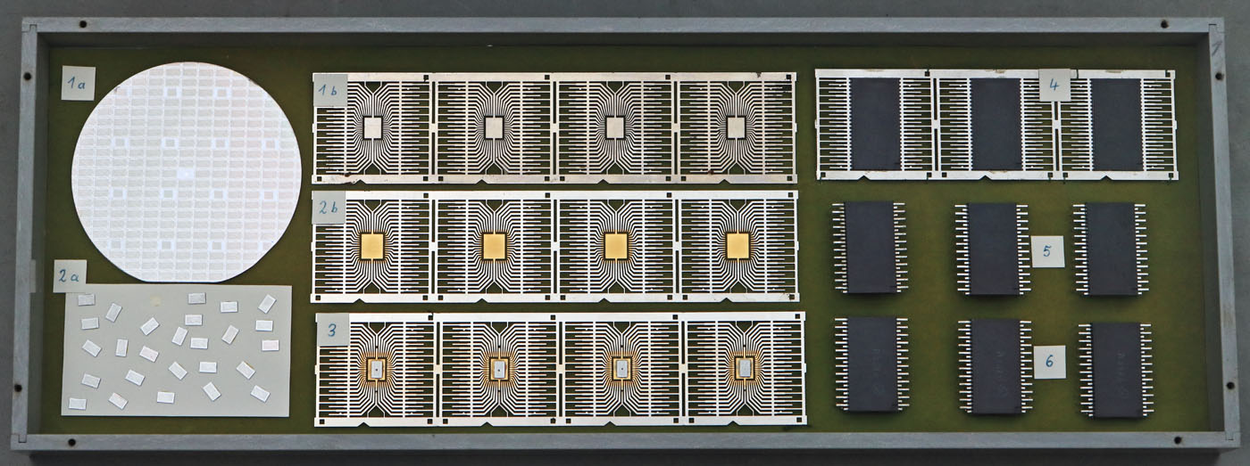
This collection can be found in the Thuringian Museum of Electrical Engineering (https://www.elektromuseum.de/). It shows the various processing steps in the manufacture of the U809M.


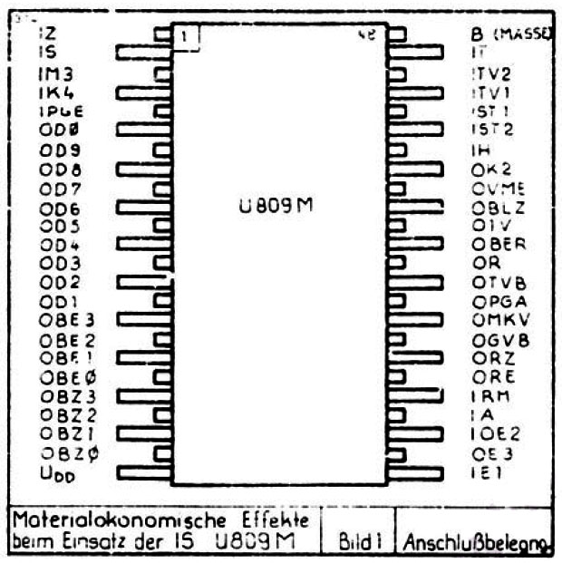
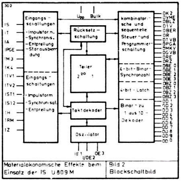
The U809M is a special circuit and you don´t find very much information about it. In the component comparison list of the Kombinat Mikroelektronik it is listed under the designation "Vermittlungs IS" for telephone systems. The above two pictures are taken from the paper "Materialökonomische Effekte beim Einsatz der IS U809M". This paper was shown in 1983 at the "Halbleiterbauelemente-Symposium", which was regularly organized by the "Halbleiterwerk Frankfurt Oder".

The paper explains that the U809M is a customized circuit developed for the ATZ 65 automatic telephone exchange. The U809M replaces electromechanical assemblies. Using 10.000 of the integrated circuits could save 44kg of precious metal, 7t of nickel silver, 12t of copper and 19t of magnetic switch iron. The U809M was developed at Funkwerk Erfurt in cooperation with the Fernmeldewerk Anrstadt.


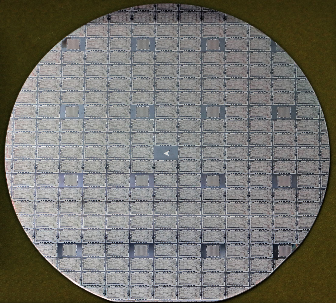
In the collection of the Thuringian Museum of Electrical Engineering there is a 3" wafer as a starting point. The flattening at the lower edge shows that it is a p-doped substrate with a (111) crystal structure. There are a relatively large number of test structures between the circuits. The wafer contains estimated 181 complete U809M circuits. The size of the U809M (5,5mm x 3,4mm) significantly reduces the yield. On a smaller 2" wafer, in contrast, it was possible to integrate 1128 of the comparatively much smaller D220 (edge length 1,2mm, https://www.richis-lab.de/wafer01.htm).


The test structure has the designation MT7. MT seems to have been a standard designation for test structures. On the 4" wafer with the U3230 (https://www.richis-lab.de/wafer04.htm), the test structures bear the designation MT21S.

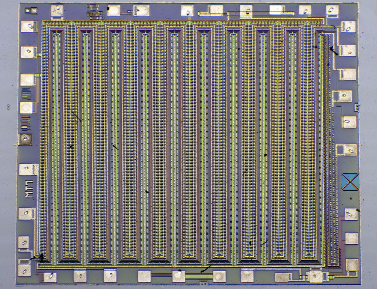
The largest part of the area is taken up by a folded structure. Various small elements are integrated around the perimeter.


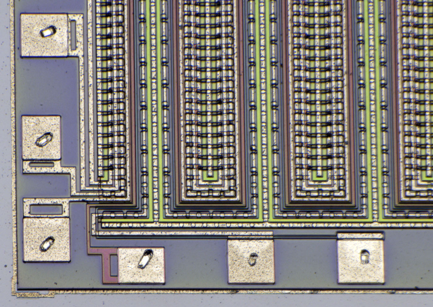
The folded test structure is quite complex. The part connected at the lower edge represents a large transistor. The rest seems to contain special forms of transistors or transistor-like structures.


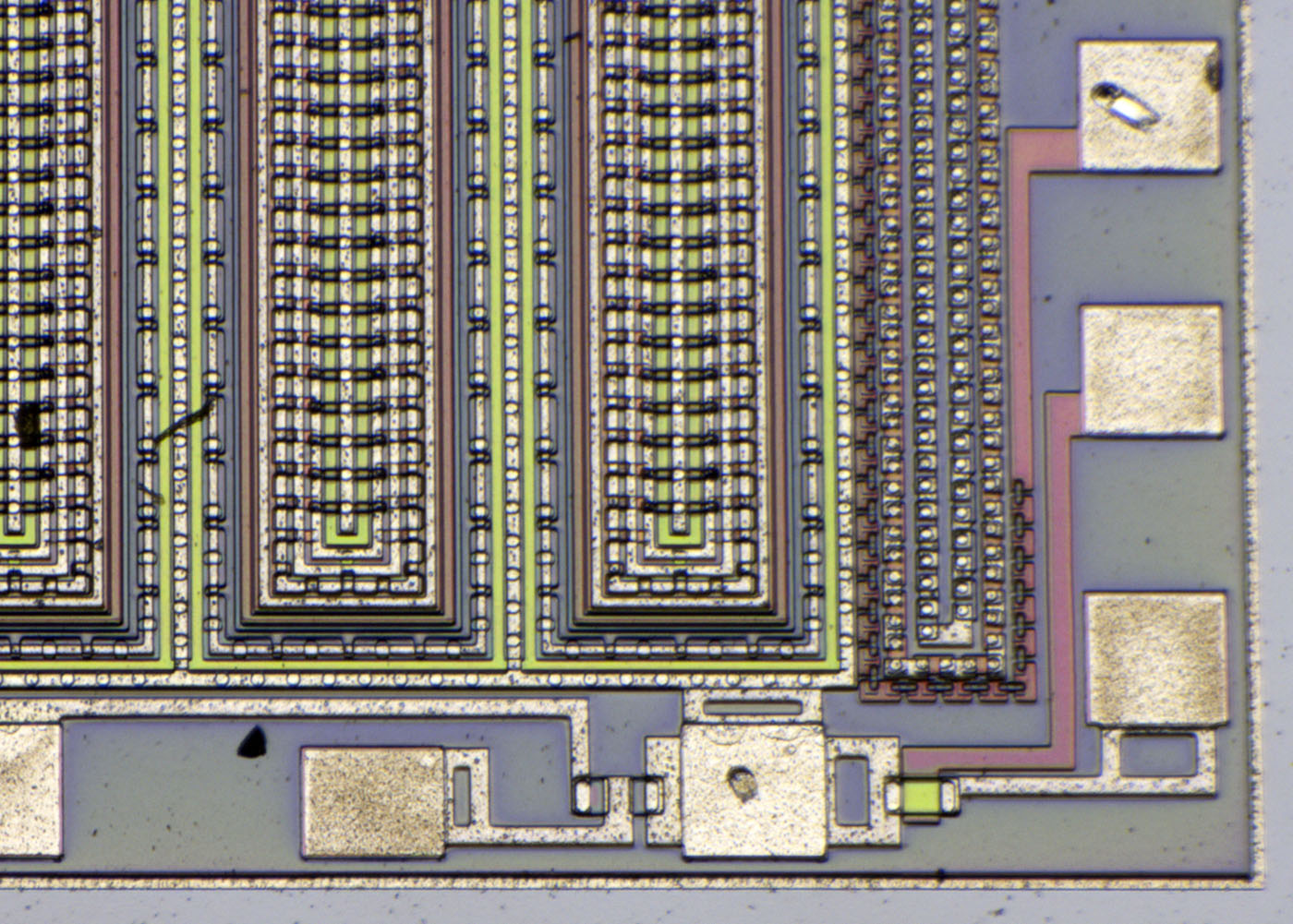
At the right edge one can measure a series of vias. At the lower edge, a metal gate and a polysilicon gate MOSFET can be seen.


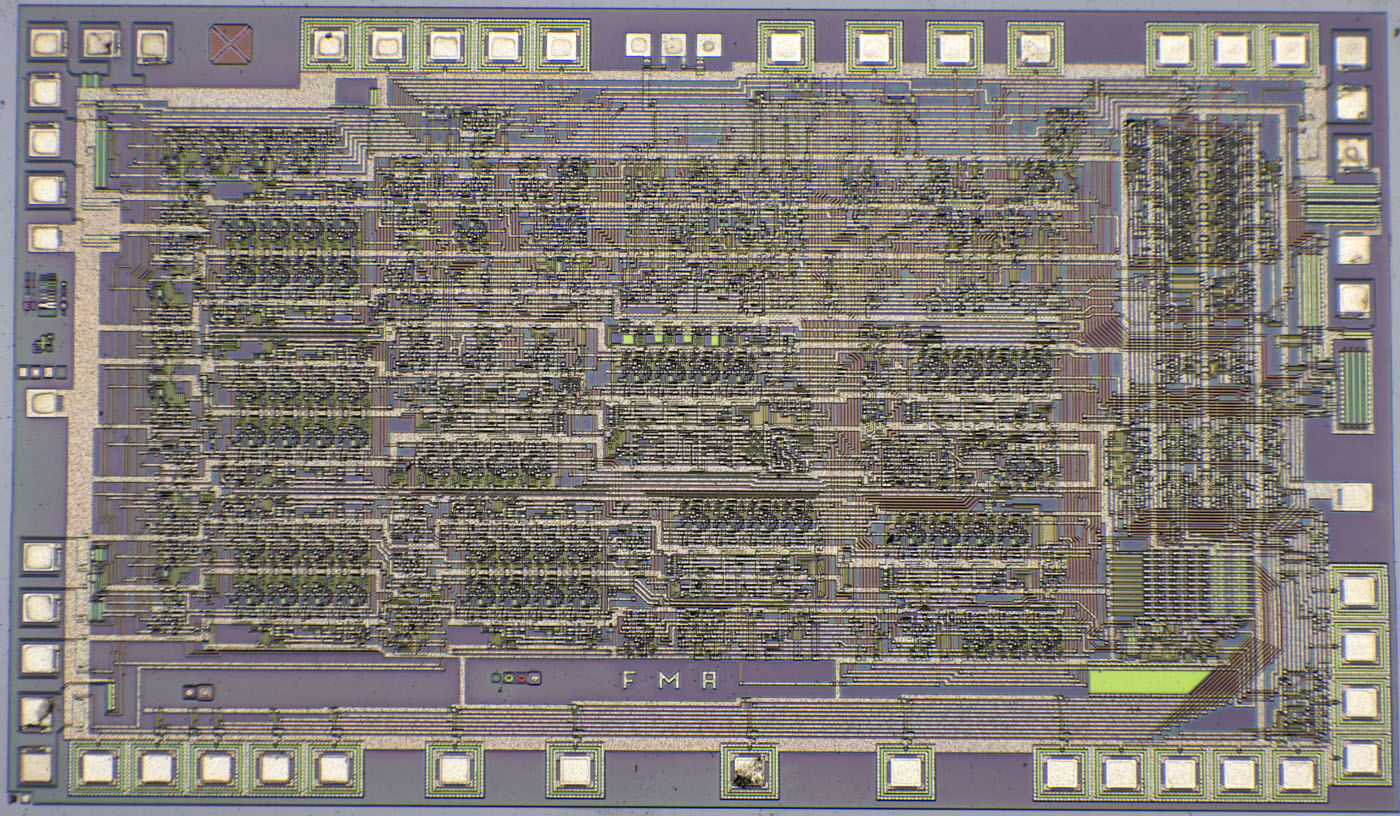
According to the Semiconductor Symposium paper the circuit measures 5,5mm x 3,4mm, contains 3191 transistors and is based on p-channel silicongate technology.


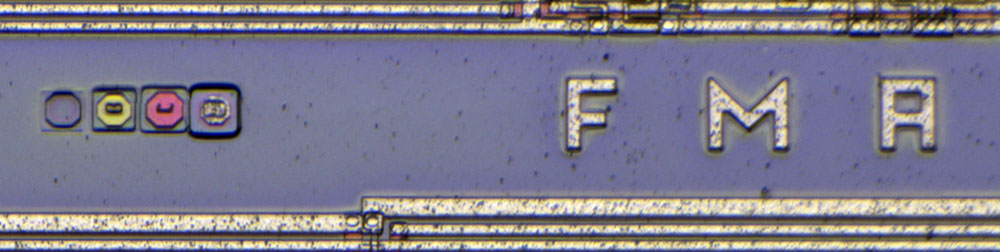
At the bottom of the die there are the letters FMA, which could be a clue to the developers.


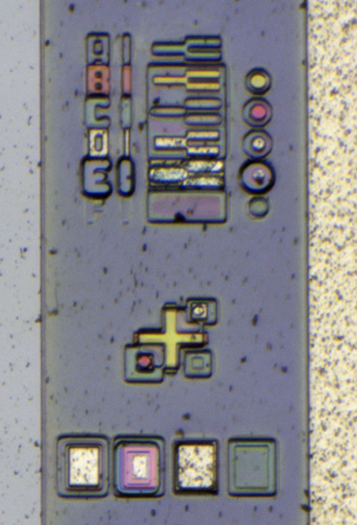
On the left edge of the die you can see the masks used and their revisions: A1, B1, C1, D1, E1 and F1. Mask A1 opens the field oxide (FOX), which initially protects the wafer and thus defines the active areas. B1 then structures the polysilicon. The polysilicon appears red on the FOX, while it appears yellowish in the active area.

After the polysilicon a full-surface n-dopant is applied, which penetrates into the open active regions. These areas are then isolated from the p-doped substrate. Where the polysilicon is located above the active areas, the n-doping is shielded so that the PMOS transistors form underneath. This simultaneously ensures that the polysilicon gate is directly above the p-channel ("self-aligned gate").

D1 is the metal layer, so C1 must be the mask for the vias. After everything has been covered with a protective oxide layer, mask E1 opens the bond areas. What remains is mask F1, which can hardly be seen. The purpose remains unclear. If the arrangement agrees with the chronological sequence, it could be that with this last process the bonding surfaces were additionally coated in some way.  :-//

The cross with the squares makes it possible to evaluate the alignment of the masks against each other.


At the upper edge there are two test structures. A PMOS transistor is shown on the right. On the left, there is an interruption in the active area under the polysilicon, so that the polysilicon rests on the thick FOX. At this point, the polysilicon should have no influence, otherwise parasitic transistors may be created in the circuit.

The minimum structure widths are in the range of round about 10µm.


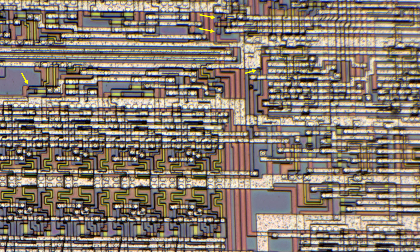
The circuit parts can be easily recognized due to the large structures.


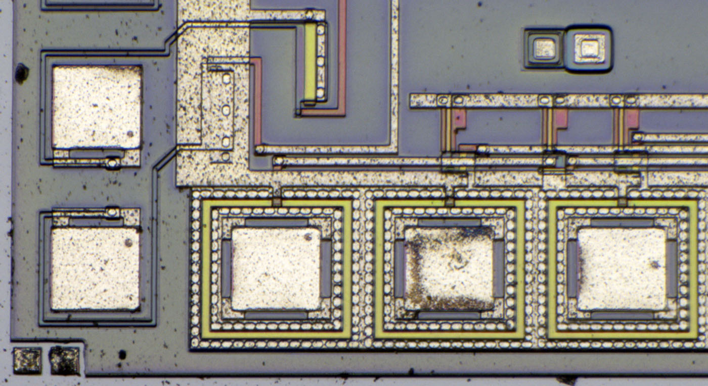
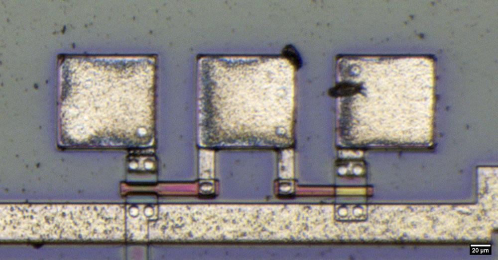
The Semiconductor Symposium document explains that the U809M has a total of 30 open-drain outputs with a common source connection. The implementation of these output stages is very unusual. One has built the transistor directly around the bondpad. The green appearing gate electrode separates the potential of the bondpad from the frame which carries the common source potential. Integrated above the output stages are the elongated transistors connected as pull-down resistors. Between the pull-down structures and the output stages, somewhat hidden, are the driver transistors that can pull the gate of the output stage transistors to a high level.

In addition to the outputs, the U809M has 13 inputs, two of which can be seen here on the left edge. A long thin line leads from the bondpad to a protection structure. The line serves as a current limiting resistor in case the protection structure becomes conductive. A slightly larger transistor serves as protection against positive voltages. Finally, it is a PMOS logic which is supplied with 0V (bulk) and -13V (Vdd). If the voltage at an input rises to positive values, the protection structure becomes conductive and limits the voltage. It could be that the structure is also protective at negative voltage peaks and thus is the complementary equivalent to the so-called "Grounded Gate NMOS".


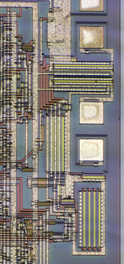
On the right edge there is a circuit whose structures clearly deviate from the rest of the logic structures. This is the RC oscillator (bottom), which outputs two complementary clock signals via two bondpads (top).


[...]

 
The following users thanked this post: SeanB, RoGeorge

Online NoopyTopic starter

  • Super Contributor
  • ***
  • Posts: 1737
  • Country: de
    • Richis-Lab
Re: Different die pictures
« Reply #246 on: November 09, 2022, 08:31:19 pm »


The Thüringer Industriearchiv (http://www.archive-in-thueringen.de/de/archiv/view/id/238) contains an illustration of the structures. The structures are shown mirrored.


The basis for the U809M is a metal grid.


The surface in the center of the metal grid is apparently gold-plated. It can be assumed that the surface plating was necessary in order to be able to display robust bond joints.


The individual dies are cut out of the wafer with a special diamond saw and soldered onto the metal grid. The die here is marked with a varnish dot. The circuits are tested on the wafer. Defective elements are equipped with a varnish dot and normally not processed further.

After the die is soldered on the metal grid, the bond connections are created between the circuit and the metal grid.


The dark potting compound usually consists of an epoxy and various fillers. It protects the IC from environmental influences and also from light incidence. The compound must initially be very thin so that the bondwires are not damaged. It must also be ensured that the starting materials and the substances that may be produced during curing do not have any negative effects on the chip, the bondwires or the metal grid. The potting compound must be as thermally, mechanically and chemically stable as possible after curing. In addition, the coefficient of expansion should be as similar as possible to the other materials so that no cracks occur during temperature changes.


After the components are cut out of the metal grid, the pins are bent and coated with a layer of tin.

The package is called Quad In-line Package (QUIP).


Finally, the lettering is applied, in this case with the logo of the Funkwerk Erfurt.


Here you can see a later series version of the U809M. Although some of the lettering has already dissolved, you still can see the letters VD, which indicate a production in December 1987.

Instead of the Funkwerk Erfurt logo the letters MME for VEB Mikroelektronik "Karl Marx" Erfurt can already be seen here.


There are no differences to the upper U809M. Just the letters FMA have been removed.


The mask revisions show that the design has been completely overhauled once.


https://www.richis-lab.de/wafer05.htm

 :-/O
 
The following users thanked this post: SeanB, doktor pyta, RoGeorge

Online NoopyTopic starter

  • Super Contributor
  • ***
  • Posts: 1737
  • Country: de
    • Richis-Lab
Re: Different die pictures
« Reply #247 on: November 10, 2022, 05:08:48 am »
For those who read the text on my website on a smartphone:
I had a small bug in the html-code. Now the pictures should look fine... :-/O

Offline RoGeorge

  • Super Contributor
  • ***
  • Posts: 6207
  • Country: ro
Re: Different die pictures
« Reply #248 on: November 13, 2022, 08:04:38 am »
TSP #216 - Detailed RFIC Analysis of the Analog Devices GaAs 81-86GHz I/Q Direct Down-Converter MMIC
The Signal Path


The following users thanked this post: MegaVolt

Online NoopyTopic starter

  • Super Contributor
  • ***
  • Posts: 1737
  • Country: de
    • Richis-Lab
Re: Different die pictures
« Reply #249 on: November 23, 2022, 07:46:07 pm »


Tele Quarz Group CCO 200, a TCXO. Does anybody own a datasheet for this part?

A TCXO is a temperature compensated oscillator. It compensates the frequency drift electrically. It´s not a OCXO, which heats the quartz to a constant temperature.


In the TCXO a voltage proportional to the temperature is generated (red). The temperature-dependent voltage modulates the capacitance of a varactor (yellow), which is connected to the quartz resonator (grey). The change in capacitance shifts the resonant frequency and thus compensates for the temperature drift. With one pin the capacitance and thus the frequency of the quartz resonator can additionally be modified externally. An oscillator (purple) generates the clock signal, which is output via an output stage (blue).


The case consists of a base plate and a lid that is soldered to it. There are five pins: power supply, ground, reference voltage output, tuning input and clock output.


In the lid there is a kapton foil, which ensures insulation of the circuit against the lid. The housing has a very solid design with a wall thickness of 1mm. The large mass guarantees some inertia of the temperature inside compared to the ambient temperature. This ensures that even rapid temperature fluctuations can be compensated.


The circuit of the TCXO is implemented on a two-layer board without solder resist. Vias were not galvanized, but realized with wires. The quality of the board doesn´t look very good.  :o


The bottom plate of the case is insulated with a Kapton foil too. The ground pin at the bottom left was soldered directly to the case.


On the top of the board, in the upper right corner, the TL431 (https://www.richis-lab.de/REF27.htm) shunt regulator generates the supply and reference voltage of the circuit (green). Judging by the resistors, the output voltage is 3,6V. A 15V zener protects the shunt regulator from too high input voltages.

The left area of the board contains the temperature measurement (red). The black bead is the temperature sensor. A TL062 opamp (https://www.richis-lab.de/Opamp60.htm) uses this sensor to generate a control voltage proportional to temperature. Mounting options allow for gain and frequency response adjustments. The choice of the TL062 is surprising since, according to the datasheet, this opamp is specified for a supply voltage of at least +/-5V. The 3,6V single supply of the TL431 is much too low in comparison. We have talked about the real minimum supply voltage of the TL062 but 3,6V seems to be way too low.  :-//

The control voltage of the temperature measurement is fed into the lower right corner, where the resonant frequency of the quartz resonator is shifted via the capacitance diode BBY40 (https://www.richis-lab.de/Diode09.htm). The external voltage for adjusting the clock frequency is brought in in the lower right corner. While the internal control voltage is connected between the capacitance diode and the quartz resonator, the external tuning voltage contacts the node between the capacitance diode and the capacitor, which leads to GND.


On the bottom side of the PCB you can see most of the distribution of the supply and reference voltage. While the oscillator and the first buffer stage are supplied directly from the TL431, there is a second path which is decoupled with a RC network. This path supplies the temperature measurement, the output stage and is output via the REF pin. Although no datasheet is available, it can be assumed that the REF pin is intended to supply a potentiometer, which is then used to generate the control voltage for the frequency adjustment.

In the lower part of the board is the oscillator (purple), which generates the desired clock frequency with the help of the quartz resonator and a BFS17 high frequency transistor (https://www.richis-lab.de/BipolarA13.htm).

This is followed by a buffer amplifier with a BFS17 (cyan), which drives the output stage with another BFS17 (blue). The placement options in this area probably serve to be able to set different output levels.


The quartz resonator has no labeling, not even on the bottom.


In the housing of the quartz resonator there is a round quartz crystal.


A metal layer was applied to both sides of the quartz crystal and soldered to the sides of the contact elements.


It is noticeable that the crystal is cloudy towards the edge.


Here you can see the surface in detail.


Apart from the soldered areas, the contact plates fix the quartz disc just relatively loosely.


The thickness of the quartz disc is 0,12mm.


https://www.richis-lab.de/osc_03.htm

 :-/O
 
The following users thanked this post: SeanB, RoGeorge


Share me

Digg  Facebook  SlashDot  Delicious  Technorati  Twitter  Google  Yahoo
Smf