Author Topic: ESD protection again :D  (Read 12020 times)

0 Members and 1 Guest are viewing this topic.

Offline truhlik_fredyTopic starter

  • Regular Contributor
  • *
  • Posts: 62
ESD protection again :D
« on: April 04, 2011, 01:33:43 am »
I read couple threads on forums what I could find, but still I don't feel satisfied. I know this is kind of washed up topic, but still I want to ask :)

First I wanted to avoid the whole thing and pain and just get IC designed for it, I got MAX6818 and when it arrived I realized that it has 40ms debouncer integrated. So it's more for somebody with mechanical switches on input, but I wanted to measure 3ms signals with it, so not usable.

In second step I designed similar circuit as it's in the third, but instead inverter I had resistor bridge and instead 4.7V zener I had 5.1V, to pull up and curent limiting resistor were smaller. I tried to simulate it in LTSpice and it looked very good, but I used similar parts and I don't know exactly how weak will be input signal and how it work in real life (IRL there would be much more hidden resistors and I don't know how it would work with mine bridges, pull ups etc... and it looked for me to complicated for simulate it 100% properly)

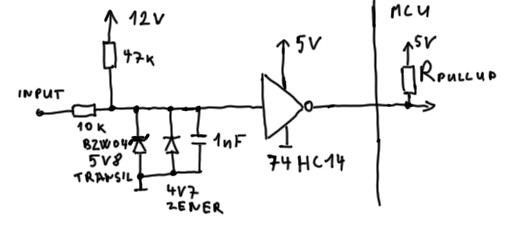
So I decided to do differently in last step I got rid of the resistor bridge and replaced it with 74HC14, they have schottky diodes so it's next level of protection and it's signal booster, so I don't need to know what values is PullUP resistor in MCU and I will know that the inverters output will have proper voltage levels (with the resistor bridge I wasn't 100% sure). Then next problem is that I don't have 5V transil diode and I can't buy it (even if I could find it in some distributors cataloge, they would ship it very expensively like 60 euro, so I usually buy parts from sites like eBay and similars...). The lowest value is 5.8V transil (400W), to make it frendly for inverters input I put there 4.7 zener diode (1W). Then I have there weak pullup 47k (I'm not sure if I should put there even higher value) and when desired it will be pull down. And series resistor of 10k, I hope for general automotive purpose it will be OK, not to low to disturb the signals in car and not to high to have decent signal for MCU.


So I can you criticize me if it's OK to use it in my car? (At the moment it's one off project and this parts I have available,  using cheaper parts that I don't have available in my junk box won't help me)

Thanks Anton.
 

Offline DrGeoff

  • Frequent Contributor
  • **
  • Posts: 794
  • Country: au
    • AXT Systems
Re: ESD protection again :D
« Reply #1 on: April 04, 2011, 02:13:39 am »
You may want to consider using a series inductor as well.
Was it really supposed to do that?
 

Offline truhlik_fredyTopic starter

  • Regular Contributor
  • *
  • Posts: 62
Re: ESD protection again :D
« Reply #2 on: April 04, 2011, 03:56:54 pm »
You may want to consider using a series inductor as well.

To make low pass filter?
 

Alex

  • Guest
Re: ESD protection again :D
« Reply #3 on: April 04, 2011, 11:06:25 pm »
Hi,

What are you trying to do with this circuit? What is connected at 'Input'?

Alex
 

Offline truhlik_fredyTopic starter

  • Regular Contributor
  • *
  • Posts: 62
Re: ESD protection again :D
« Reply #4 on: April 05, 2011, 03:00:14 pm »
Hi,

What are you trying to do with this circuit? What is connected at 'Input'?

Alex

Many different things, like injectors, distributor signal, open doors, open boot, handbrake, break, clutch / neutral position, oil pressure signal, alternator charging signal. Many of them are like switches and need debounce, that is done in software. Couple other (injectors and distributor) have big spickes and, in the distributor, signal IGN- is just the spike measured, in injectors is the gorund level measured, but it has spike on the and of impulse.
 

Alex

  • Guest
Re: ESD protection again :D
« Reply #5 on: April 05, 2011, 04:13:16 pm »
Given the slow nature of these signals you can increase your input resistance and drop the other protection measures, effectively using the resistor in series with the internal clamping diodes. You can leave in the capacitor to suppress very high frequency spikes, it will have little effect on the useful signals. The pull-up inside the MCU is not needed either. Why do you have a pull-up to 12V?
 

Offline truhlik_fredyTopic starter

  • Regular Contributor
  • *
  • Posts: 62
Re: ESD protection again :D
« Reply #6 on: April 05, 2011, 04:30:57 pm »
Given the slow nature of these signals you can increase your input resistance and drop the other protection measures, effectively using the resistor in series with the internal clamping diodes. You can leave in the capacitor to suppress very high frequency spikes, it will have little effect on the useful signals. The pull-up inside the MCU is not needed either. Why do you have a pull-up to 12V?

Switches yes, but the INJ and IGN- aren't slow. Pull-up to 12V / GND (depending on signal) it's there for signals which are disconnected (I think the ECU in the car is High-Z) when inactive and have GND when active, that's for mostly switches. I think IGN- is disconected and just when it's making impulse it has about 60V.
 

Online Zero999

  • Super Contributor
  • ***
  • Posts: 19524
  • Country: gb
  • 0999
Re: ESD protection again :D
« Reply #7 on: April 05, 2011, 05:33:37 pm »
It looks much more complicated than it needs to be.

The MCU input will almost certainly have clamping diodes build in and the same is true for the 74HC14.

Connect a 1M resistor in series with the input with a varistor across the ESD prone side.
 

Offline DrGeoff

  • Frequent Contributor
  • **
  • Posts: 794
  • Country: au
    • AXT Systems
Re: ESD protection again :D
« Reply #8 on: April 05, 2011, 10:23:54 pm »
Given that the OP suggested the circuit was for automotive use I'd also put a series ferrite inductor on the input. Test it with a 1.2/50us 5kV impulse and see if it survives.
Was it really supposed to do that?
 

Offline truhlik_fredyTopic starter

  • Regular Contributor
  • *
  • Posts: 62
Re: ESD protection again :D
« Reply #9 on: April 06, 2011, 01:54:49 am »
Given that the OP suggested the circuit was for automotive use I'd also put a series ferrite inductor on the input. Test it with a 1.2/50us 5kV impulse and see if it survives.

I don't have equipotent to test it. And it perhaps just one-off with small possibility of more quantities in future. But at the moment I just don't want to do something stupid and the replacing the device and redesigning the inputs. I saw somewhere just 50k resistor and zener diode as protection.
 

Offline truhlik_fredyTopic starter

  • Regular Contributor
  • *
  • Posts: 62
Re: ESD protection again :D
« Reply #10 on: April 08, 2011, 01:28:51 am »
It looks much more complicated than it needs to be.

The MCU input will almost certainly have clamping diodes build in and the same is true for the 74HC14.

Connect a 1M resistor in series with the input with a varistor across the ESD prone side.

So I will get rid of the 74HC14 (it's mentioned in datasheets that there is ESD protection, but it's not clarified).
Shouldn't I keep the Pull Ups and Pull downs after the series resistor, on some places I'm not 100% sure if it's pulled down/up by ECUside and I would like to not change any performance of car and charasterics, for example the injectors are at idle hight (12V), but I'm sure if the ECU is HIGH-Z or PullUp because the 12V could go from injector itself which is connected nonstop to 12V rail. And another example if the supply got some interference and my suplly input would be filtered then my circuit could make difference in potentials and could interfere with injector itself, something like LED, if I will put 14V on one side and 11V on otherside then it will lit.
 

Online Zero999

  • Super Contributor
  • ***
  • Posts: 19524
  • Country: gb
  • 0999
Re: ESD protection again :D
« Reply #11 on: April 08, 2011, 03:57:09 pm »
So I will get rid of the 74HC14 (it's mentioned in datasheets that there is ESD protection, but it's not clarified).
The 74HC is only required if you need a Schmitt trigger input. If your code is written to ignore glitches then there should be no need for it.

Quote
Shouldn't I keep the Pull Ups and Pull downs after the series resistor, on some places I'm not 100% sure if it's pulled down/up by ECUside and I would like to not change any performance of car and charasterics, for example the injectors are at idle hight (12V), but I'm sure if the ECU is HIGH-Z or PullUp because the 12V could go from injector itself which is connected nonstop to 12V rail.
The ECU probably has push pull outputs but if it doesn't you need to look at using pull-up/down resistors. The MOV should act as a weak pull-down but if it's not good enough then connect a pull-up/down resistor on the MOV side.

Quote
And another example if the supply got some interference and my suplly input would be filtered then my circuit could make difference in potentials and could interfere with injector itself, something like LED, if I will put 14V on one side and 11V on otherside then it will lit.
What do you mean? The MCU could interfere with the ECU? Do you have any ECU inputs connected to the MCU? There's no chance of an MCU input connected via a 1M resistor interfering with the MCU, if there's a bug in the code and somehow the input is set to an output, the 1M resistor should prevent it from interfering with the ECU.
« Last Edit: April 08, 2011, 09:20:45 pm by Hero999 »
 

Offline Bloch

  • Supporter
  • ****
  • Posts: 453
  • Country: dk
Re: ESD protection again :D
« Reply #12 on: April 08, 2011, 06:59:44 pm »
Hi Anton

Maybe I am overlooking something. But why not use an optocoupler ?

Regards,
Lars
 

Online Zero999

  • Super Contributor
  • ***
  • Posts: 19524
  • Country: gb
  • 0999
Re: ESD protection again :D
« Reply #13 on: April 08, 2011, 09:21:23 pm »
Hi Anton

Maybe I am overlooking something. But why not use an optocoupler ?

Why use an opto-coupler?
 

Offline truhlik_fredyTopic starter

  • Regular Contributor
  • *
  • Posts: 62
Re: ESD protection again :D
« Reply #14 on: April 08, 2011, 10:28:17 pm »
Quote
What do you mean? The MCU could interfere with the ECU? Do you have any ECU inputs connected to the MCU? There's no chance of an MCU input connected via a 1M resistor interfering with the MCU, if there's a bug in the code and somehow the input is set to an output, the 1M resistor should prevent it from interfering with the ECU.

I more meant the MOV could interfere. I don't know how much current is enough to change behavior. The injector is mechanical, so perhaps it's not to bad, but on some other places are just electrical. So when I imagined that whatever I will connect to the device it will be after series resistor. Perhaps 20k and then pull up/down so I will be sure that under any conditions I will draw/supply minimum current that won't affect cars sensors and components. Pull down perhaps are not always necessary but that other thing that it looks like that ECU has pull ups/downs but not 100% sure and I don't have proof, and many times is not easy to take measurements where I needed to. So having pull up/down would exclude that "perhaps" and I would be sure that always it has proper levels. And then the ESD protections itself. So I wanted have universal building block what I would blindly use on any inputs inside my car (12V, 60V from ignition coil,switches, electronic sensors) and I would have just adjust the pull up or down and had free of mind that I won't alter behavior of my car and it won't fry my MCU.
 

Offline truhlik_fredyTopic starter

  • Regular Contributor
  • *
  • Posts: 62
Re: ESD protection again :D
« Reply #15 on: April 08, 2011, 10:36:29 pm »
Hi Anton

Maybe I am overlooking something. But why not use an optocoupler ?

Regards,
Lars

I'm not sure If I'm correct and my information are right, but for couplers you need to drive the diode, so it needs current and I don't won't to draw anything that big that it could lit something. Then I could get the galvanic isolation but that is overkill and still if I'm correct it won't save the opto from frying. So anyway my device will stop wroking, right the MCU will be safe, but the device won't be working, perhaps if I will make couple copies in future nobody will be interested if it's big deal and everything is damaged or small part which will prevent it from working, still it won't be working.  And I think the device without the coupler could be more robust (not galvanic isolated), but still more durable so everything will work even will withstand what could the opto version fry.
 

Offline Bloch

  • Supporter
  • ****
  • Posts: 453
  • Country: dk
Re: ESD protection again :D
« Reply #16 on: April 09, 2011, 03:06:21 am »
It looks much more complicated than it needs to be.
I agree.

But if it was me i would add a  parallel capacitor 100nF to the input pin.

Anton I dont know if you have seen this app. note http://www.freescale.com/files/microcontrollers/doc/app_note/AN2764.pdf At page 27 it is about
input signals.

Regards,
Lars
 

Offline Bloch

  • Supporter
  • ****
  • Posts: 453
  • Country: dk
Re: ESD protection again :D
« Reply #17 on: April 09, 2011, 03:08:58 am »
I don't won't to draw anything that big that it could lit something.

Ok
 

Online Zero999

  • Super Contributor
  • ***
  • Posts: 19524
  • Country: gb
  • 0999
Re: ESD protection again :D
« Reply #18 on: April 09, 2011, 08:16:34 am »
But if it was me i would add a  parallel capacitor 100nF to the input pin.

Anton I dont know if you have seen this app. note http://www.freescale.com/files/microcontrollers/doc/app_note/AN2764.pdf At page 27 it is about input signals.
It depends on the desired cut-off frequency.

The circuit on page 27 of the paper you linked to has a 1k series resistor so the RC time constant would be 100us. The circuit I posted has a 1M resistor so the RC time constant would be 100ms.
 

Offline Bloch

  • Supporter
  • ****
  • Posts: 453
  • Country: dk
Re: ESD protection again :D
« Reply #19 on: April 09, 2011, 10:52:57 am »
you linked to has a 1k series resistor  / The circuit I posted has a 1M resistor

That is just a minor detail  ;)

I still think there should be a capacitor. 
 

Online Zero999

  • Super Contributor
  • ***
  • Posts: 19524
  • Country: gb
  • 0999
Re: ESD protection again :D
« Reply #20 on: April 09, 2011, 11:13:22 am »
I disagree, I don't think having a cut-off frequency of 1.6Hz vs 1.6kHz (the circuit you posted)  or 16kHz (my circuit assuming 10pF of input capacitance) is a minor detail.

By all means put a capacitor there as long as you're aware of the consequences.
« Last Edit: April 09, 2011, 11:50:57 am by Hero999 »
 

Offline Bloch

  • Supporter
  • ****
  • Posts: 453
  • Country: dk
Re: ESD protection again :D
« Reply #21 on: April 09, 2011, 05:44:37 pm »
I disagree

So do I. That was the smiley if you do wonder.

Have a nice weekend

Regards,
Lars
 

Offline truhlik_fredyTopic starter

  • Regular Contributor
  • *
  • Posts: 62
Re: ESD protection again :D
« Reply #22 on: April 09, 2011, 06:31:18 pm »
By all means put a capacitor there as long as you're aware of the consequences.

I'm not saying you are wrong, the MCU has diodes, if the current will be kept low while discharge, then they should be grand and with 1M resistor it should be low. So it should be reasonable protection, but somehow it looks like just too simple to be true. And then why there is so much fuzz about ESD...

Another question if I will make 2 revision, 1 yours and 1 mine. What should I alter on my design? I have for example 5.1V zenner, so I could swap it with 4.7V it will have slight over voltage but the HIGH level will be kept on higher voltage (if that matters at all). And other like resistor values, cap value. I tried to pick just blindly some, are they all to be used in real circuit?


Online Zero999

  • Super Contributor
  • ***
  • Posts: 19524
  • Country: gb
  • 0999
Re: ESD protection again :D
« Reply #23 on: April 09, 2011, 07:28:44 pm »
I'm not saying you are wrong, the MCU has diodes, if the current will be kept low while discharge, then they should be grand and with 1M resistor it should be low. So it should be reasonable protection, but somehow it looks like just too simple to be true. And then why there is so much fuzz about ESD...
There's an application note on Microchip's website showing a PIC input connected to the mains via a high value resistor.
 

Offline truhlik_fredyTopic starter

  • Regular Contributor
  • *
  • Posts: 62
Re: ESD protection again :D
« Reply #24 on: April 12, 2011, 05:47:13 am »
There's an application note on Microchip's website showing a PIC input connected to the mains via a high value resistor.

Yes but MCU is not Microchips but many others, in my case Atmel, and they should have diodes there, its mentioned in one app note (not in datasheet), but never any closer specification. So I have impresion from them that they are there but I should not be 100% relaying only on them (because the app note could be write by sales/reps/managment and in datasheet where are real facts there it is not even mentioned). And mains are not same as automotive environment. And I believe you, with 1M it should be OK and I will try it out, but I want to try my design as well.
And about my design, besides that you think it's overkill, is there something that could be considered as very bad? Cap value to high? PullUp res. value to low?


Share me

Digg  Facebook  SlashDot  Delicious  Technorati  Twitter  Google  Yahoo
Smf