-
Foward looking sonar
Posted by
B J
on 20 Feb, 2018 20:37
-
Have looked for a fish finder/depth finder, but cannot come up with what I want. They have side looking devices, but still not quite what I am looking for. Any input and/or ideas would be greatly appreciated. If I can’t find one, will build my own. I think for a few hundred bucks it can be done. -------- I want basically a forward looking sonar. I will be in uncharted waters and want to be able to follow channels and detect deep holes and shallows ahead of me. I will be looking for targets with distance and directional information data, presented on a panel screen. What is available on the markets, give some of this information underneath you, and a history of what is behind you, time wise. -------- If I can’t find what I want on the market, I will be back here and would like to bounce some ideas off this group. My background is electronics, however I have been out of the game for awhile and not up on the latest components and equipment that is out there. Thanks for any and all comments…..
Is this the best place for this ?
-
#1 Reply
Posted by
ogden
on 20 Feb, 2018 21:20
-
No need to build one:
-
#2 Reply
Posted by
GerryBags
on 20 Feb, 2018 21:42
-
Yup, I had one on my ancient grand banks that I added. Echopilot, mine was called. It looks in a fan shape ahead and below. 300m ahead, 150m down. Excellent bit of kit. In rough weather you could see the reflections off the inside curves of waves.
https://echopilot.com/
-
#3 Reply
Posted by
B J
on 21 Feb, 2018 03:12
-
Thanks for the info. on Simrad. Interesting, however does not appear to give me the information I am looking for. It will indicate that a target is out in front somewhere, but does not indicate where. I want to know where that target is with relation to the front of the boat. Distance, right, left, or center! What is the azimuth, heading, of it. I need to be able to see the channel, holes, and shallows ahead of me, and know the location, not just that there is something somewhere out front. Also it appears that this one works with charts. There are none in some of the areas. From reading their information, it appears they basically took the transducer and pointed it forward, instead of down. Also in the installation, it is mounted protruding out the bottom of the hull. Not acceptable. ==== Maybe I missed something, but still looking Thx
-
#4 Reply
Posted by
GerryBags
on 21 Feb, 2018 03:39
-
I'm not sure if the latest models have been improved, but the one I had had a very thin, fan shaped arc. Just looked. They have the 2D, which I had, and now the 3D:
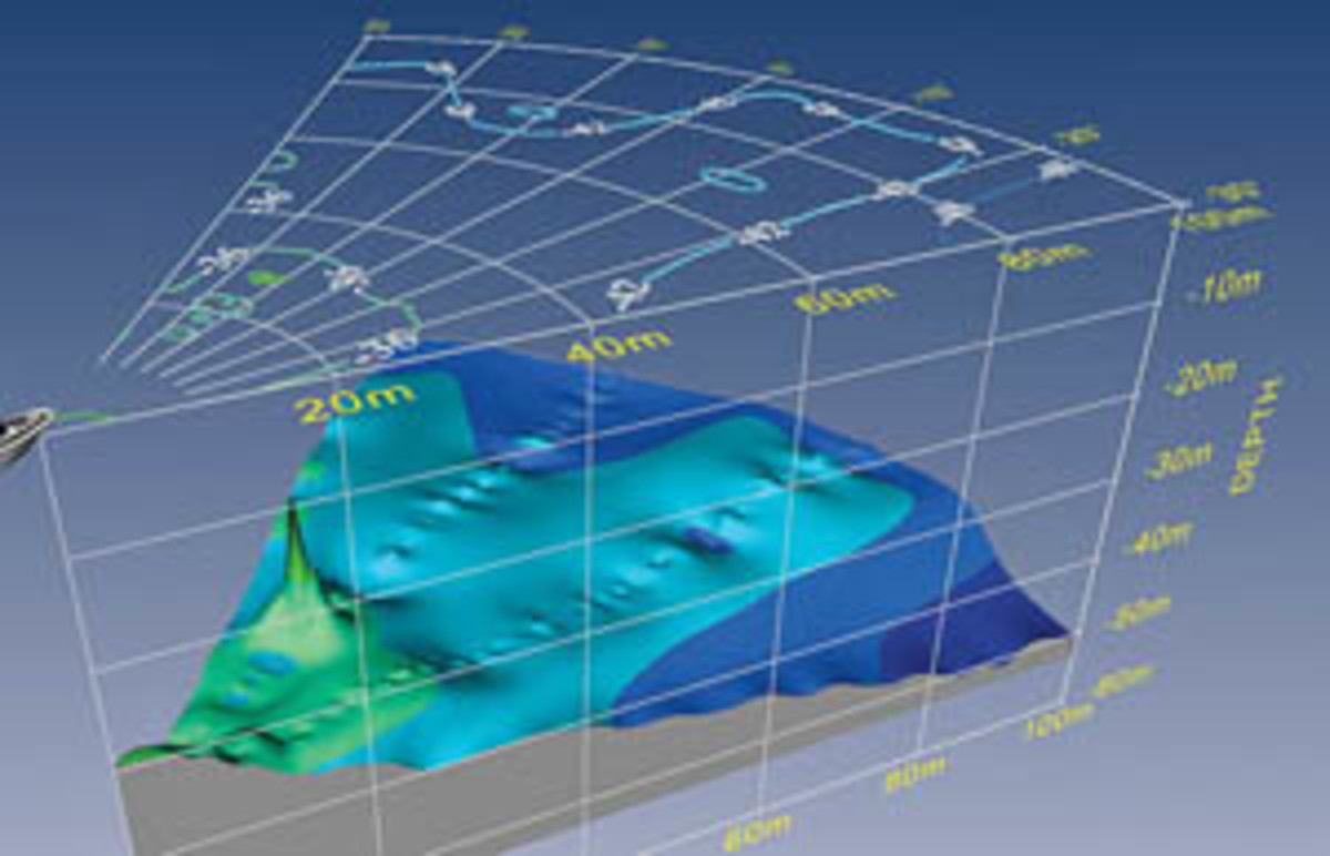
Here's the 2D's FOV. It was fine for me, the old girl could only make 9 knots with a following wind, but I can see how a fast boat would want to be able to see much farther off either bow to gauge turns and plan ahead to avoid anything that triggers the zone alarms. Neat feature, by the way. It warns you of any large returns if they get within a set range in one of the guard zones.
-
#5 Reply
Posted by
B J
on 21 Feb, 2018 05:32
-
Gerry, now you have my attention. Looks very promising. Not quite what I envisioned building, but I do believe it would do the job. I sent a letter to them requesting more data and pricing. I am holding my breath until the price comes in. I may still have to proceed with some of my own head scratching. Thnx
-
#6 Reply
Posted by
dmills
on 21 Feb, 2018 15:26
-
Electronically beamformed arrays are **expensive** especially if you go for a large number of beams.
It might be practical to do something with two crossed interferometric sonars (an array of three long narrow receive transducers where phase differences are used to resolve bearing), but there would sometimes be ambiguities.
Failing that something beamforming in one plane and using interferometry in the other might work, both are processing tricky, think GPU or decent FPGA.
The real elephant in the room however is the transducer design, and waterproofing, PUR resins are your friends, but make sure you get good wetting, and be aware that much cable turns out to be slightly hydroscopic when left in a bilge for a year, PUR is good for this, PVC not so much.
If doing your own transducer designs, you will need a surface grinder and probably some diamond slitting saws, plus resins, vacuum (For degassing), silvering and the ceramics themselves (Morgan electro ceramics are one possible supplier), that and a whole pile of acoustics know how.
Regards, Dan.
-
#7 Reply
Posted by
GerryBags
on 21 Feb, 2018 15:45
-
Gerry, now you have my attention. Looks very promising. Not quite what I envisioned building, but I do believe it would do the job. I sent a letter to them requesting more data and pricing. I am holding my breath until the price comes in. I may still have to proceed with some of my own head scratching. Thnx
Maybe tell them you're developing a bridge automation system or something and you need all the fls specs to make it compatible on a deeper level than SeaTalk, maybe?
What DMills said about the waterproofing is a very salient point. I don't think there are many hulls where you could get away with not using a thru=hull transducer for fls. I had no choice with a very thick hull. I had the echopilot transducer fitted by Buckie Shipyard, where they do all the maintenance work (or used to) for the RNLI boats and which had been run bu the former owner of my boat. It still took them three attempts to stop water fountaining into the bilges from the transducer when she was launched. I got her slipped to avoid point loading the hull on their hoists, but that went out of the window after the first launch. She got got whipped out, creaking alarmingly, onn their big hoist and shut down the rest of their work for a couple of days. Professionals, harumph.
-
#8 Reply
Posted by
dmills
on 21 Feb, 2018 16:12
-
Hulls do change shape when you flood the dock, just the way it is, especially if you have a large amount of ballast.
Bash some oakum and putty into the gap and call it good!
The transducer also wants to be deep enough to avoid cavitation on transmit, but that is mainly an issue at low frequency and with hull designs that transition from displacement to planing at normal operating speeds, speaking of which feeding inclinometer data to the display is useful it helps to compensate for changes to the geometry as you heel over.
Regards, Dan.
-
#9 Reply
Posted by
Marco
on 21 Feb, 2018 18:12
-
Electronically beamformed arrays are **expensive** especially if you go for a large number of beams.
It might be practical to do something with two crossed interferometric sonars (an array of three long narrow receive transducers where phase differences are used to resolve bearing), but there would sometimes be ambiguities.
Are simple piezo discs not sensitive enough to make hydrophones? A 2D 256 element phased array receiver build from simple piezo discs wouldn't need cost much. Use a phase sensitive lock in amplifier to detect response/phase without need for a fast ADC per channel.
-
#10 Reply
Posted by
dmills
on 21 Feb, 2018 23:02
-
The things are massively high Q (Which means very poor range resolution) and are a horrible acoustic impedance match to water (No surprise water is about 1.5M rayl, air is about 400 rayl, a difference of 3,500 times or so).
You would be better doing it with 1nF type II dielectril MLCCs, with the added bonus that FR4 has an acoustic impedance about geomertrically half way between most of the ceramics and water, so a 1/4 wave thick sheet makes a decent match.
Also, on transmit, such things would be massively beamy, very difficult to get wide transmit coverage (And they are usually only good for a hundred V or so).
Regards, Dan.
-
#11 Reply
Posted by
Berni
on 22 Feb, 2018 10:52
-
Even if you don't use fast ADCs you still need a lot of copies of your circuitry. But if the ADC if fast enough one can use sample and hold chips to feed a bunch of channels into only a few ADCs.
But transducer design is likely also an art in itself.
-
#12 Reply
Posted by
dmills
on 22 Feb, 2018 11:20
-
Transducer design is something of a black art, albiet one almost entirely amenable to numerical methods. We used such things as genetic algorithms (To design matching networks), and 2D FEM (to design the acoustic geometry).
The design is one thing, the practicalities of building something reliable are something else.
I worked in that area for a few years, some years back.
73 Dan.
-
#13 Reply
Posted by
Marco
on 22 Feb, 2018 11:43
-
The things are massively high Q (Which means very poor range resolution)
You don't have to use them at resonance as a receiver.
-
#14 Reply
Posted by
dmills
on 22 Feb, 2018 13:10
-
No, but you need to use something to put a reasonable amount of power in the water.
Also, the acoustic impedance issue very much remains.
Regards, Dan.
-
#15 Reply
Posted by
Marco
on 22 Feb, 2018 15:45
-
No, but you need to use something to put a reasonable amount of power in the water.
A fishfinder transducer can do that.
Also, the acoustic impedance issue very much remains.
Just put some PU rubber on top of 1 MHz transducers and try it out, who knows ... might work.
That said, that 3D version of the Echopilot is impressive and supposedly available for 7K$. It uses
uses a 4x4 array of rectangular piezo transducers by the way.
-
#16 Reply
Posted by
dmills
on 22 Feb, 2018 20:25
-
Not going to get much range in sea water at 1MHz!
It is not totally infeasible for an imaging sonar for close work, but for collision detection at at 100M?
That patent is classic intefereometry sonar, with some processing tacked on to do the sensor fusion between the multiple arrays, no idea how they got that thing issued.
TI have an interesting AFE that just happens to be 16 channels.....
Regards, Dan.
-
#17 Reply
Posted by
Marco
on 22 Feb, 2018 23:52
-
Not going to get much range in sea water at 1MHz!
That's not the point, they are cheap, roughly the right size (ie. wavelength in water) and have a resonance frequency well above the frequencies of interest.
They would be the hydrophones to build your phased array (although I prefer to think of it as a holographic camera). The emitter would be some off the shelf unit from AIRMAR probably, let them worry about juggling Q and efficiency ... it's only necessary for the transmitter., since that would be the only one operating at resonance.
-
#18 Reply
Posted by
dmills
on 23 Feb, 2018 11:43
-
That thing is not classical phased array beamforming, but instead uses three unequally spaced elements in each beam to measure both time of flight and relative phase between the elements (Three, unevenly spaced to help resolve the ambiguity in arrival bearing).
I am not at all sure that fishfinder transducers really have the beam shape for this, but I suppose they MIGHT work.
The time of flight gives the range and the relative phase across the array gives the bearing.
This is done in both azimuth and elevation and then a pile of sensor fusion and interpolation happens to give a pretty looking picture.
This kind of interferometry is very commonly used in side scan survey sonars because it provides good data on the bottom profile out to a reasonable range allowing a more widely spaced survey grid (which saves a lot of time).
Regards, Dan.