Hello all,
I'm looking to create a breakout board for a 3V3-only I2C sensor. I'd like to be able to use the sensor with both 5V and 3V3 microcontrollers and have been reading the Philips app note AN97055
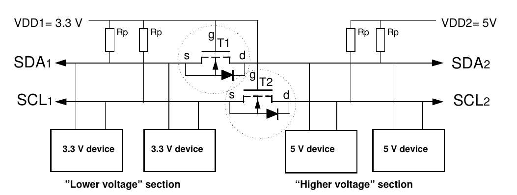
www.adafruit.com/datasheets/an97055.pdf? (warning, pdf) which details a bi-directional MOSFET-based level shifting circuit.
The circuit as given in the data sheet is below, with the pull-up resistors on each side of the level shifting MOSFETs connected to different supplies.
Now in order to use the circuit on a breakout board and allow use with either 5V or 3V3 micros, would the following be correct? - The principal deviation from the app note being that all pull-up resistors are permanently tied to 3V3 regardless of whether the "high-side" logic levels are indeed higher at 5V or the same at 3V3. (The headers on the breakout board are the breaks & text in the green outline on the right hand side of the diagram.)
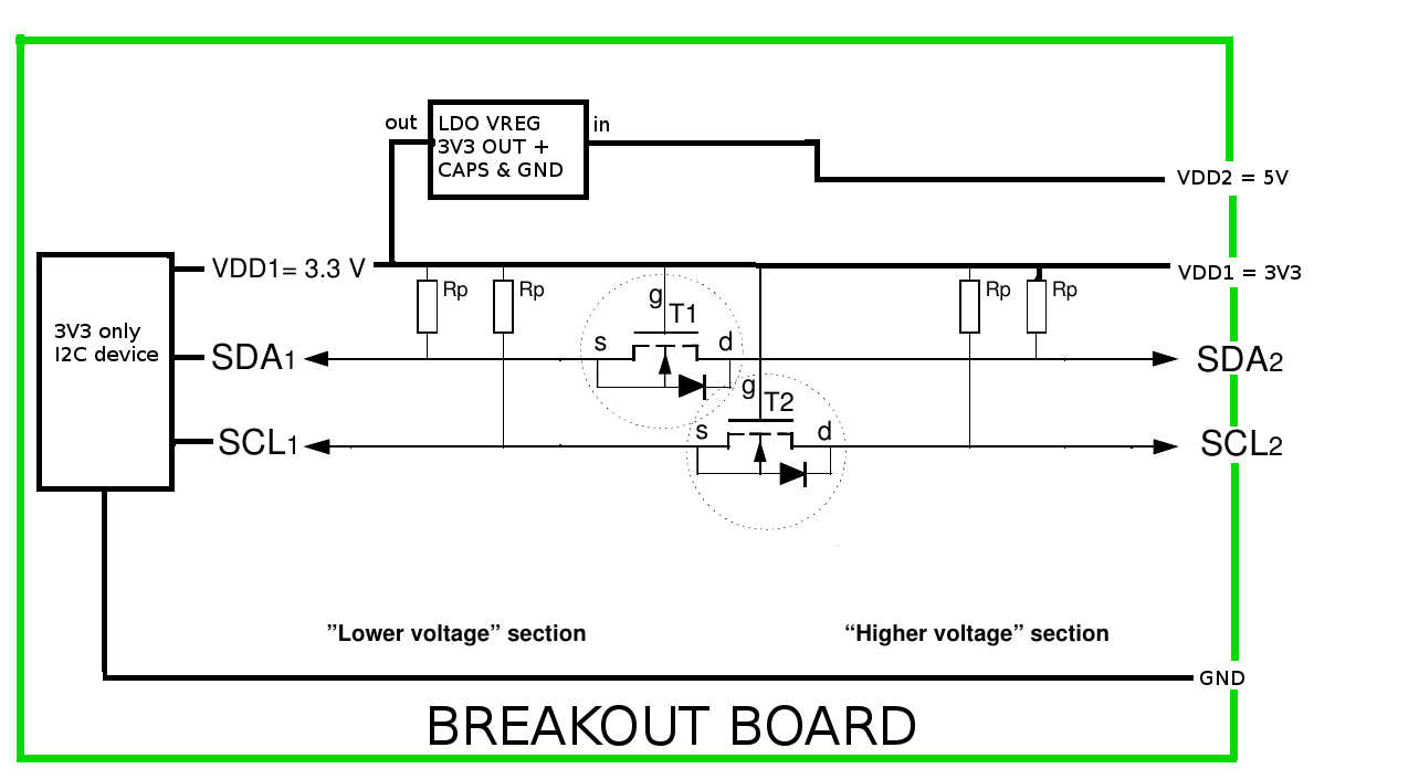
Please excuse the melding of circuit diagram and block diagram, I'm still in the planning stage for this project and haven't fired up KICAD yet,
thanks,
Richard
that won't work (well). it might work but its not correct.
I built one using that schematic (funny proto shown here):

its ok to laugh. it makes me laugh and I built the damned thing

all I had on hand was the tiny smd mosfets and so I did the best I could to hand/air wire them.
but anyway, you have to tie the pullups to the LOCAL Vcc, be it 5v on one side or 3.3 on the other.
the general idea is that it sits at the 'right' high level and gets pulled down on 0's. a zero is a zero to all logic (more or less) but a high could be 5v or 3v.
so its best to not try to redefine what 'high' is for the A or B side or your circuit.
(btw, this build of mine certainly redefines what it means to use GLUE LOGIC. hahahaha)
I'd use a chip made for this purpose. Much easier.