Author Topic: instability due to transfer function peaking  (Read 1496 times)

0 Members and 1 Guest are viewing this topic.

Offline john23Topic starter

  • Frequent Contributor
  • **
  • Posts: 511
  • Country: aq
instability due to transfer function peaking
« on: March 05, 2026, 01:11:59 pm »
Hello,In the video at 7:46 and the photo below  they say that a drop of 180 degrees and a massive peak is a sign of instability.

but in theory we have the formula taken from the attached article where they say that gain needs to be 1 (0dB) and phase 180 , because that way the denomiator will be 0 (unstable)

So how a peak of 20dB in theory will make the system unstable?
As i see it the transfer function will be stable with 20dB peak.
Thanks.

https://www.rcet.org.in/uploads/academics/rohini_62708204869.pdf
 

Online mawyatt

  • Super Contributor
  • ***
  • Posts: 6109
  • Country: us
Re: instability due to transfer function peaking
« Reply #1 on: March 05, 2026, 01:39:20 pm »
He's showing a RLC network in the video.

With a Negative Feedback System the Transfer Function is:

Vo/Vi = A/(1+A*B), where A is the forward gain and B is the feedback.

So where A*B = -1 (gain magnitudes = 1 and phase 180 degrees), then the "System" becomes unstable, as the denominator -> 0. Usually Phase and Gain Margins describe the relative stability of the "System".

Hope this helps.

Best
Curiosity killed the cat, also depleted my wallet!
~Wyatt Labs by Mike~
 

Offline Andy Watson

  • Super Contributor
  • ***
  • Posts: 2340
Re: instability due to transfer function peaking
« Reply #2 on: March 05, 2026, 01:59:29 pm »
I believe "transfer function" refers only to the filter design. When he says "system", I think he is referring to the filter and whatever is attached to the output of the filter. A load that exhibits negative resistance could form an unstable system with a peaky filter.
 

Offline temperance

  • Super Contributor
  • ***
  • Posts: 1616
  • Country: 00
Re: instability due to transfer function peaking
« Reply #3 on: March 05, 2026, 03:29:40 pm »
The non mathematical explanation.

This is all about the incremental input impedance of the SMPS, which is negative because it is a constant power circuit, and the output impedance of the filter. The output impedance of the mains filter |Zfilter| must be smaller than |Zin-smps|.

This is also known as the Middlebrook Criteria for stability.
 

Offline john23Topic starter

  • Frequent Contributor
  • **
  • Posts: 511
  • Country: aq
Re: instability due to transfer function peaking
« Reply #4 on: March 06, 2026, 02:41:05 pm »
Hello , so given this formula Vo/Vi = A/(1+A*B) why a 20dB peak causes instability.
Thanks.
 

Offline bson

  • Supporter
  • ****
  • Posts: 2761
  • Country: us
Re: instability due to transfer function peaking
« Reply #5 on: March 07, 2026, 05:22:20 am »
Instability is phase margin dependent, and just briefly scanning the video (sorry, I'm not going to sit through a 10 min video to answer a question) - at a glance I see no discussion of phase margin.
 

Online MariuszD

  • Frequent Contributor
  • **
  • Posts: 679
  • Country: pl
Re: instability due to transfer function peaking
« Reply #6 on: March 07, 2026, 07:45:30 am »
A passive filter cannot be unstable. However, connecting a high-Q filter to a circuit that draws current in pulses or has negative resistance can induce oscillations in it. I skimmed thru the video and there is no discussion on the topic in your question.

Quote
So how a peak of 20dB in theory will make the system unstable?
What system, there is no system, only the filter.
« Last Edit: March 07, 2026, 08:02:50 am by MariuszD »
 

Offline peter-h

  • Super Contributor
  • ***
  • Posts: 6008
  • Country: gb
  • Doing electronics since the 1960s...
Re: instability due to transfer function peaking
« Reply #7 on: August 05, 2026, 09:34:11 pm »
This looks like the best thread of several for this Q.

I am building a 10-35V to 5V 1A PSU using the MCP16366:
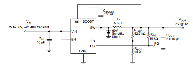

https://ww1.microchip.com/downloads/aemDocuments/documents/APID/ProductDocuments/DataSheets/MCP16364-5-6-Family-Data-Sheet-DS20006969.pdf

In front of the above circuit I am putting an LC filter, with 10uF on the input, and 6.8uH driving the above circuit. So we have 10uF on the actual input, then 6.8uH, then another 10uF which is the Cin you see above. Actually I plan to have 20uF there, for Cin.

IOW, a PI filter, of which above Cin is a part.

And I got stuck in to the Middlebrook stability stuff. In simple terms, watching the video which a number of people have posted already, the Zin of the PSU needs to be much higher than the Zout of the filter before it.

But how can this be calculated when Cin participates both in the Zout of the input filter, and Zin of the PSU?

The video gives a simple estimation formula for the Zin but that clearly ignores Cin (it takes in just Vin, efficiency, and power out). Yet every SMPS must have a Cin otherwise the conducted RF would be massive. In fact it would probably just not work at all. The formula it gives for Zout of 10uF and 6.8uH produces a value of Zout which is much much lower than the Zin, so it should be OK.

The circuit given by Microchip above will almost certainly not meet any CE standards, so I am putting in a bit of money into a decent input filter :) I am actually using the spread spectrum version of the chip... and everything will go into a shielded case, on a 4 layer PCB, so shielded on all six sides.

Unfortunately, while I understand the basics of control loop stability (open loop gain to be below 1 before the phase shift goes past 180, etc) and have designed loads of products employing control loops (most of these were succesfully substantially over-damped and worked fine) I am bad at maths and can't get my head around those formulae.

Yes the Zin must be negative; it is thus for any SMPS because a higher Vin produces a lower Iin.

I've dug around everywhere for suggested values for input filters for this chip but can't find anything. Also not for the 3A version (which has the additional problem of discontinuous operation at low loads).

Another thing is what effect would a series diode have (reverse polarity protection). Many years ago I worked in a HV PSU company (photomultiplier PSUs) and they found a series diode made them unstable. So they used a parallel diode (which blew a fuse :) ).
« Last Edit: August 05, 2026, 09:49:47 pm by peter-h »
Z80 Z180 Z280 Z8 S8 8031 8051 H8/300 H8/500 80x86 90S1200 32F417
 

Online mtwieg

  • Super Contributor
  • ***
  • Posts: 1789
  • Country: us
Re: instability due to transfer function peaking
« Reply #8 on: August 06, 2026, 01:23:36 pm »
But how can this be calculated when Cin participates both in the Zout of the input filter, and Zin of the PSU?

The video gives a simple estimation formula for the Zin but that clearly ignores Cin (it takes in just Vin, efficiency, and power out). Yet every SMPS must have a Cin otherwise the conducted RF would be massive. In fact it would probably just not work at all. The formula it gives for Zout of 10uF and 6.8uH produces a value of Zout which is much much lower than the Zin, so it should be OK.
Normally one would put all of Cin on the "source" side.
It's actually somewhat arbitrary where one draws the line between source and load. Though if you put that line in odd places (like between the input filter inductor and the Cin directly on the buck input), then the middlebrook criteria will become overly constraining. Keep in mind the middlebrook criteria is a sufficient but not necessary condition for stability.

I don't see any formula given for Zin in the video, but to be conservative one could assume the DCDC is an ideal constant-power load with infinite bandwidth, in which case you can estimate Zin from just Pin and Vin.
 

Offline peter-h

  • Super Contributor
  • ***
  • Posts: 6008
  • Country: gb
  • Doing electronics since the 1960s...
Re: instability due to transfer function peaking
« Reply #9 on: August 06, 2026, 04:41:13 pm »
I've done some more digging. Claude also seems to know this well :)

The whole issue appears to be the negative resistance of the PSU input (which is inevitable - that is how switchers work) in conjunction with the Zout of the filter (or whatever is driving the PSU).

The negative resistance of the PSU input is thus nothing to do with Cin (unless Cin is absolutely massive). So Cin needs to be considered as a part of the filter; in the proposed case a PI filter.

The PSU Zin crude formula is Zin ≈ Vin² × η / Pout, where n is the efficiency.

So the above PSU, 5V 1A, min Vin of say 8V, yields Zin=10 ohms. Well, minus 10 ohms but that's irrelevant.

For the filter Zout ≈ √(L/C) = √(6.8µH / 20µF) ≈ 0.58Ω which is way less than 10 ohms...

The Middlebrook criteria are trivially met with a PSU which inputs a reasonably high voltage e.g. 12-24V and generates a low power e.g. 5V 1A. It is much harder if you are inputting say 3V and outputting say 0.9V at 40A. Such a switcher will have a very aggressive negative resistance.

The videos and the printed stuff I've read all fail to explain it in a simple way. Probably because none of them understand it and just copy stuff from each other, to get clickbait. That's certainly what most "tech" websites do.
« Last Edit: August 06, 2026, 05:05:45 pm by peter-h »
Z80 Z180 Z280 Z8 S8 8031 8051 H8/300 H8/500 80x86 90S1200 32F417
 

Online mtwieg

  • Super Contributor
  • ***
  • Posts: 1789
  • Country: us
Re: instability due to transfer function peaking
« Reply #10 on: August 06, 2026, 05:29:43 pm »
For the filter Zout ≈ √(L/C) = √(6.8µH / 20µF) ≈ 0.58Ω which is way less than 10 ohms...
√(L/C) is the so-called characteristic impedance Z0 of the LC filter. The actual |Zout| can be much higher (depending on the Q of the filter). The damping of the LC filter reduces Q, and therefore reduces the peak |Zout|. When the filter is critically damped, preak |Zout| will be roughly equal to Z0 (depends on the specific damping circuit used).
 

Online mawyatt

  • Super Contributor
  • ***
  • Posts: 6109
  • Country: us
Re: instability due to transfer function peaking
« Reply #11 on: August 06, 2026, 06:28:17 pm »
Sometimes opening a loop to inject a signal and plot the overall system transfer function (Bode Plot) can be difficult as it might upset the system due to injection device parasitics (floating voltage source), folks used isolation transformers to help but they also have unwanted parasitics.

Something we did over 50 years ago was develop a device well called a "Pinger". This was a simple 9V battery powered probe that had a 555 timer that produced a low frequency squarewave. The squarewave was differentiated (series C shunt R) to produce a narrow pulse, the pulse was applied to a pot to allow manually setting the pulse amplitude thru a series DC coupling mylar film cap (recall 0.1uF was used). The housing was a probe case (recall we used old Heathkit VTVM probe) that has a short ground lead like a scope probe, and a sharp probe tip for the pulse.

In use the "Pinger" would inject a short impulse like waveform into the System Under Test (SUT) at a strategic location in the system feedback loop. This impulse would invoke the system closed loop response and observed with a scope. Understanding 2nd order systems (almost all closed loop systems can be considered somewhat 2nd order in impulse response) one could quickly access the SUT overall stability and damping factor. We could change system, load, power supply, and temperature parameters and quickly view the results on the scope.

Anyway, this "Pinger" proved very valuable in the lab back then, and even be useful in simulations as well, maybe even today :-+

Best
Curiosity killed the cat, also depleted my wallet!
~Wyatt Labs by Mike~
 

Offline peter-h

  • Super Contributor
  • ***
  • Posts: 6008
  • Country: gb
  • Doing electronics since the 1960s...
Re: instability due to transfer function peaking
« Reply #12 on: August 06, 2026, 07:37:53 pm »
Quote
√(L/C) is the so-called characteristic impedance Z0 of the LC filter. The actual |Zout| can be much higher (depending on the Q of the filter). The damping of the LC filter reduces Q, and therefore reduces the peak |Zout|. When the filter is critically damped, preak |Zout| will be roughly equal to Z0 (depends on the specific damping circuit used).

Right, but how is this practically applied, and is it relevant in the above actual case?


Quote
Anyway, this "Pinger" proved very valuable in the lab back then, and even be useful in simulations as well, maybe even today

Many years ago (about 50 too) I was measuring the open loop behaviour of HV PSUs to check stability margins when the loop was closed. Interesting work.
Z80 Z180 Z280 Z8 S8 8031 8051 H8/300 H8/500 80x86 90S1200 32F417


Share me

Digg  Facebook  SlashDot  Delicious  Technorati  Twitter  Google  Yahoo
Smf


-->