In Analog Device's app note MT-042, they describe this circuit and formula for measuring CMRR:
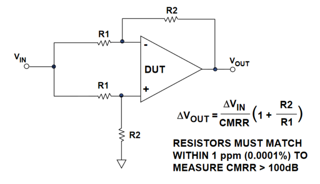
First off, is this formula right? When I solve the circuit, I get:
\[v_+ = \frac{R_2}{R_1 + R_2}v_{in}\]
\[v_- = \frac{R_2}{R_1 + R_2}v_{in} +\frac{R_1}{R_1 + R_2}v_{out}\]
\[v_{out} = A_d(v_+ - v_-) + \frac{1}{2}A_{cm}(v_+ + v_-) = \frac{A_{cm} v_{in} \frac{R_2}{R_1+R_2}}{1 + \frac{R_1}{R_1 + R_2}(A_d - \frac{1}{2}A_{cm})}\]
Under the assumption the denominator is large, the "1" drops out, and if \(A_d \gg A_{cm}\), then \(A_d - \frac{1}{2}A_{cm} \approx A_d\), so the result is
\[v_{out} = \frac{v_{in}}{A_d/A_{cm}}\frac{R_2}{R_1} = \frac{v_{in}}{\mathrm{CMRR}}\frac{R_2}{R_1}\]
Did I make a mistake in simplifying? They didn't show their work in the formula for the app note... Next, in doing simulations, what is right setup in a single-supply configuration? Should the input reference the virtual ground, like this:
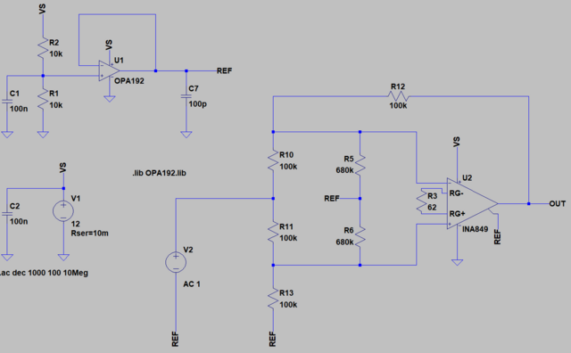
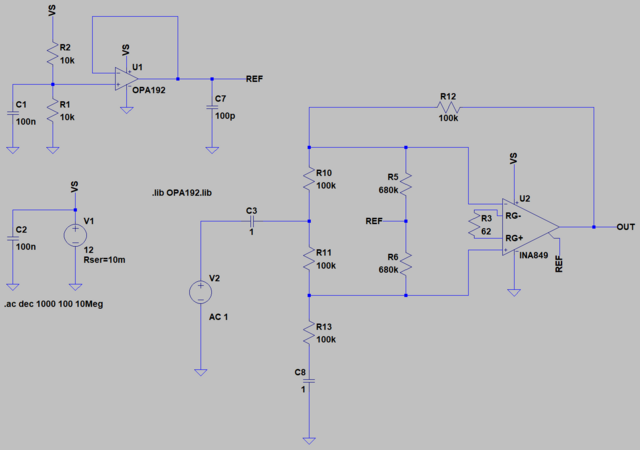
Or be AC-coupled to ground?

 Home
Home Help
Help Search
 Login
Login Register


