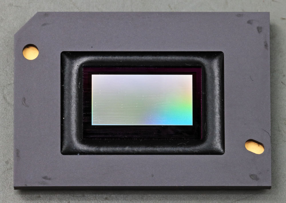
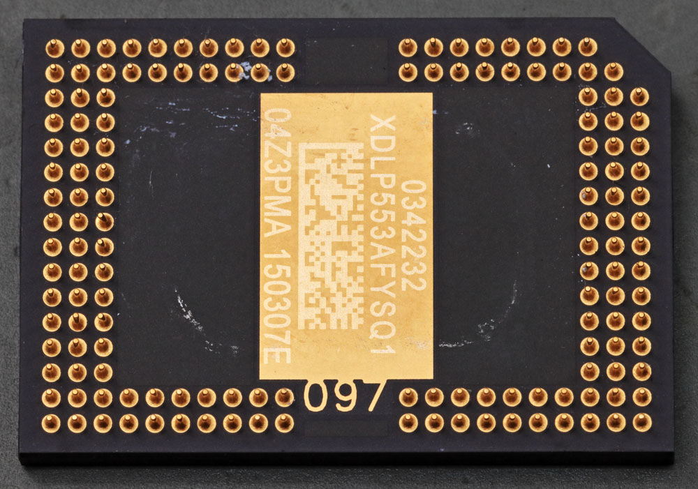
Texas Instruments produces a family of DLP units for the automotive sector: DLP553x. Accordingly, the operating temperature of the elements may be -40°C to 105°C, which is remarkable for a DLP module. The DMD1076 (
https://www.richis-lab.de/DLP.htm), which is used in beamers, is just approved up to 65°C. The DLP553x is used in headlights, among other applications. The many mirror elements enable not only very precise and adaptive illumination of the road, but also the projection of images such as warning symbols. The resolution is 1152 x 576 pixels.
The module here is named XDLP553, which can not be found in the Texas Instruments documents. The individual variants of the DLP family don't seem to differ too much, though. Partially, the aperture within the window is arranged minimally differently. The DLP5530 is also subject to a special quality management.
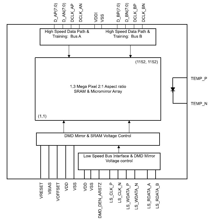
The datasheets show the basic structure of such a DLP module. As usual, the mirror array contains a SRAM placed directly under the mirrors, which contains the information how the individual pixels should be orientated. Two fast bus interfaces allow to write to this SRAM. A third bus is used to configure the DLP module, especially the voltages with which the mirrors are moved.
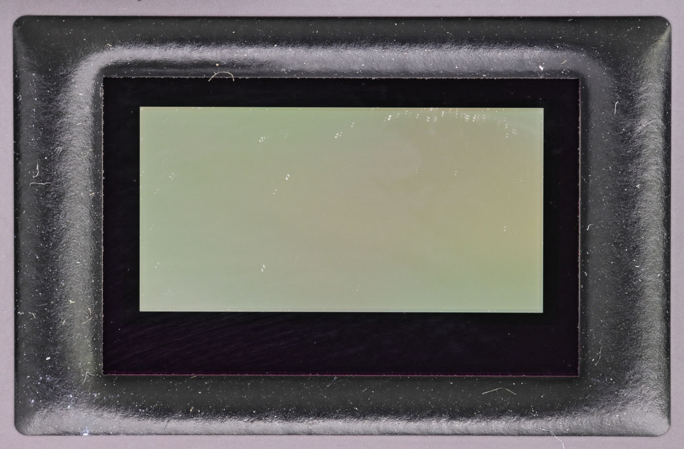
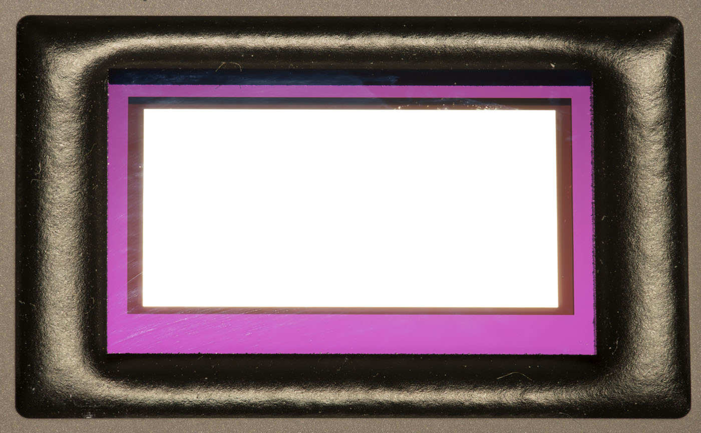
A window is glued into the ceramic housing. In the upper picture you can already see the thin inactive frame of the mirror array. In the lower picture, you can see that an aperture has been applied to the underside of the window. Parts of the integrated circuit around the mirror array are inside the aperture.
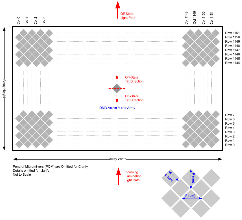
The datasheet shows the arrangement of the pixels in the DLP553x. Compared to the DMD1076, the individual mirrors are rotated by 45°. This arrangement is called a "diamond pixel array". Since the pixels partially overlap in this way, the effective resolution is just 1152 x 576 pixels, although the array consists of 1152 x 1152 mirrors. With the rotated array, the angles of incident and reflected light are more advantageous, allowing the optical system to be more compact.
The edge length of a mirror is given as 7,6µm, which apparently already includes the distance between the mirrors. The mirrors are thus significantly smaller than the mirrors of the DMD1076 (13,68µm). Around the usable mirror area there is a so-called "Pond of Micromirrors" (POM), a frame of inactive mirrors, which are not shown on the above sketch.

The POM frame is clearly visible. The necessity of this area also becomes clear. Functional mirrors can only be guaranteed inside the array due to the manufacturing process. For this reason, the mirrors are partially fixed in the POM frame. However, one must expect that individual elements are tilted.
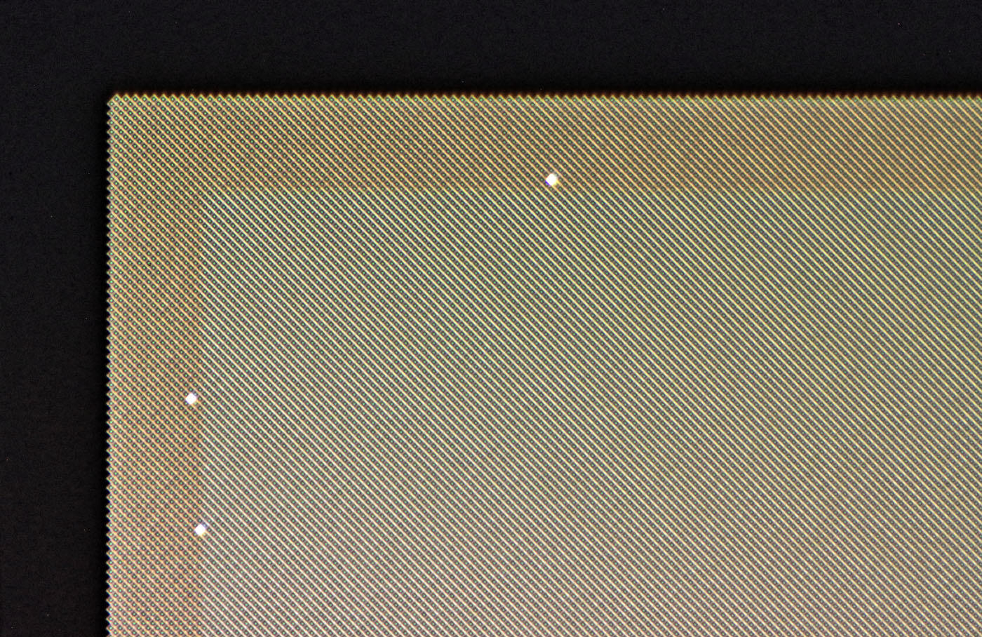
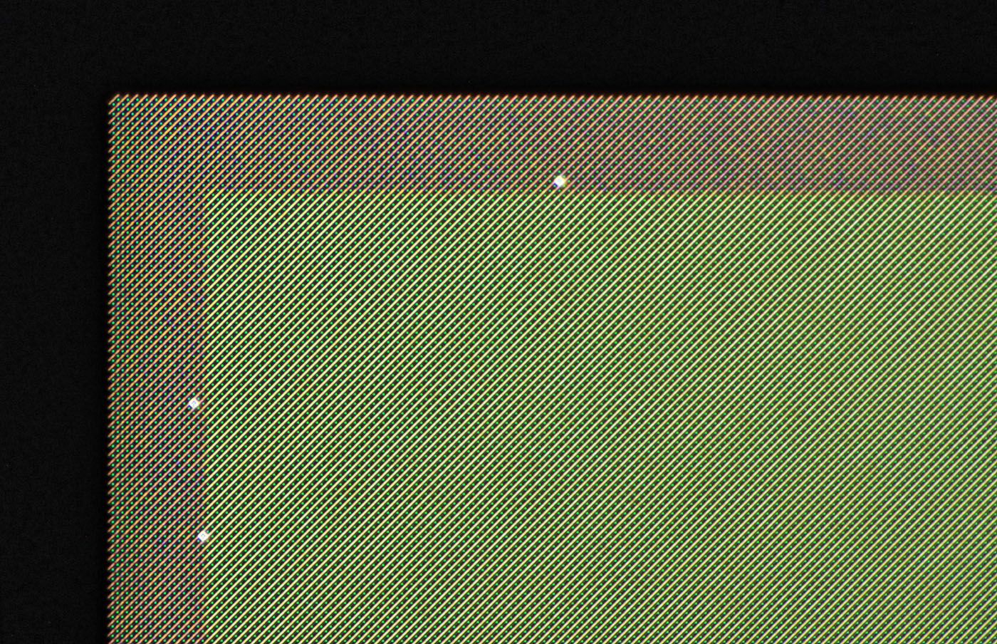
Depending on the incidence of light, the structures create very different patterns.
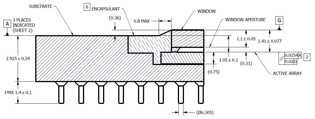
The datasheets show the constructional design of the case in section. The die is apparently slightly larger than the window. The potting in the frame provides the necessary tightness and mechanical stability.
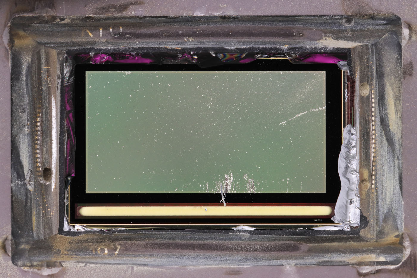
If you grind out the potting with a cutting disk, you can see some of the conductive paths that carry the potentials of the contacts to the die. In some places, you can even see the remains of the bondwires. In addition, some characters are exposed. The window still has to be broken out with some force, which damages the die a little.
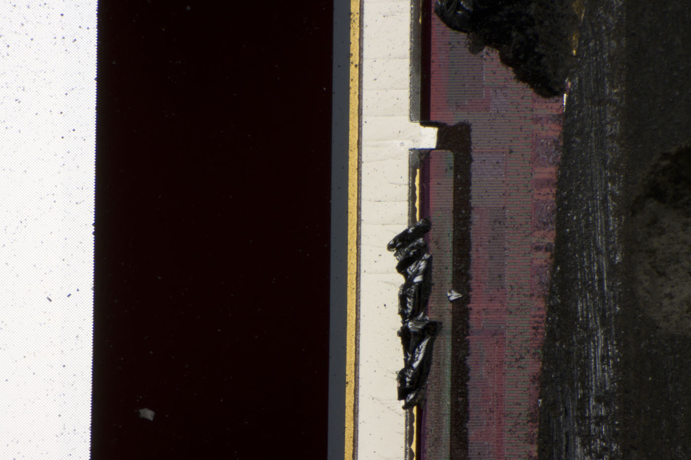
In this picture the mirror array can still be seen on the left. To the right is a coating that appears black here. On the far right parts of the metal layer of the die can be seen.
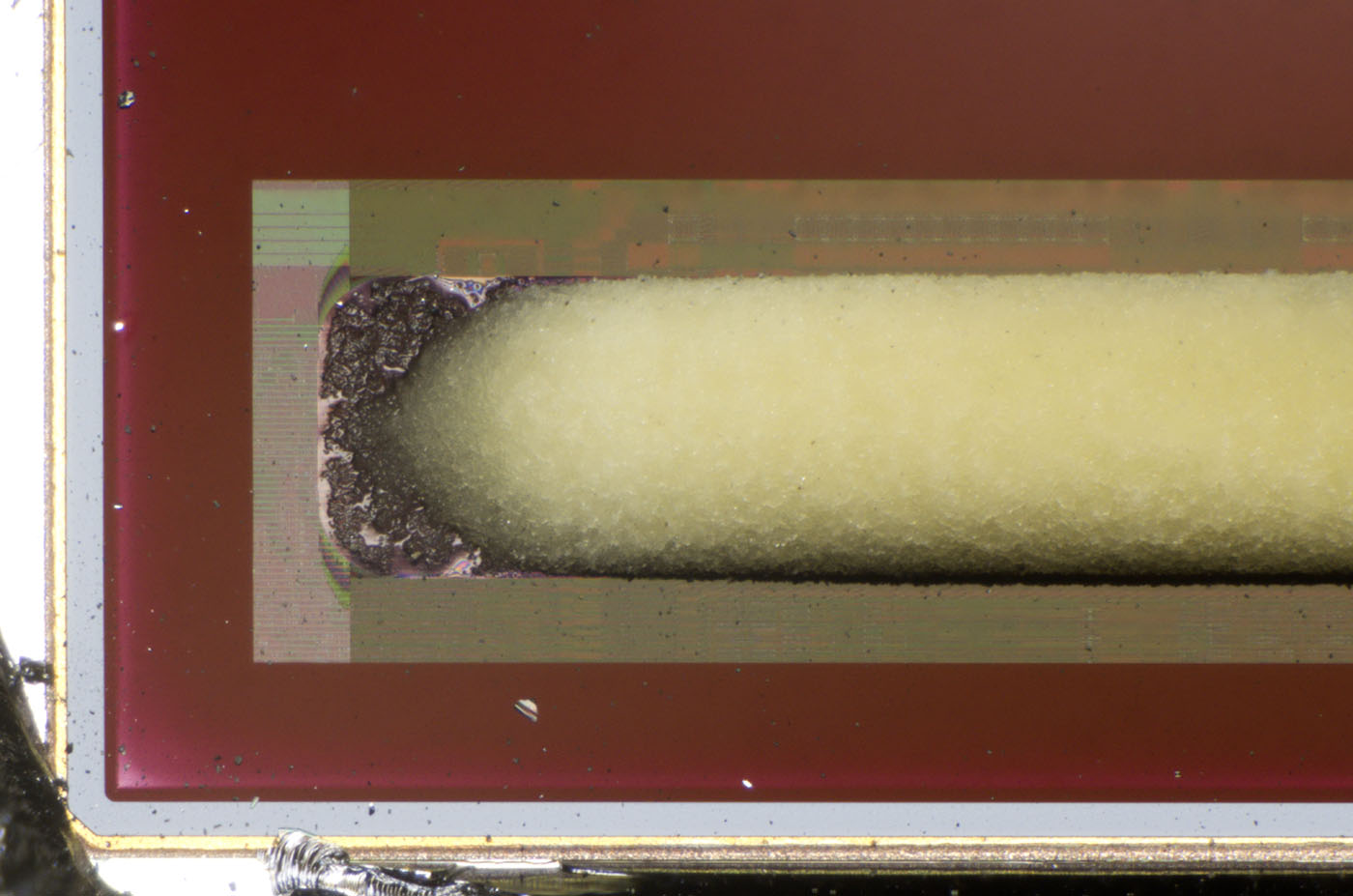
The purpose of the strip at the lower edge of the mirror matrix remains unclear. Shading of circuit parts could have been done with the coating that appears red here. It would be conceivable that it is some kind of drying agent or binder for problematic substances. However, this should actually no longer be necessary with modern manufacturing processes.

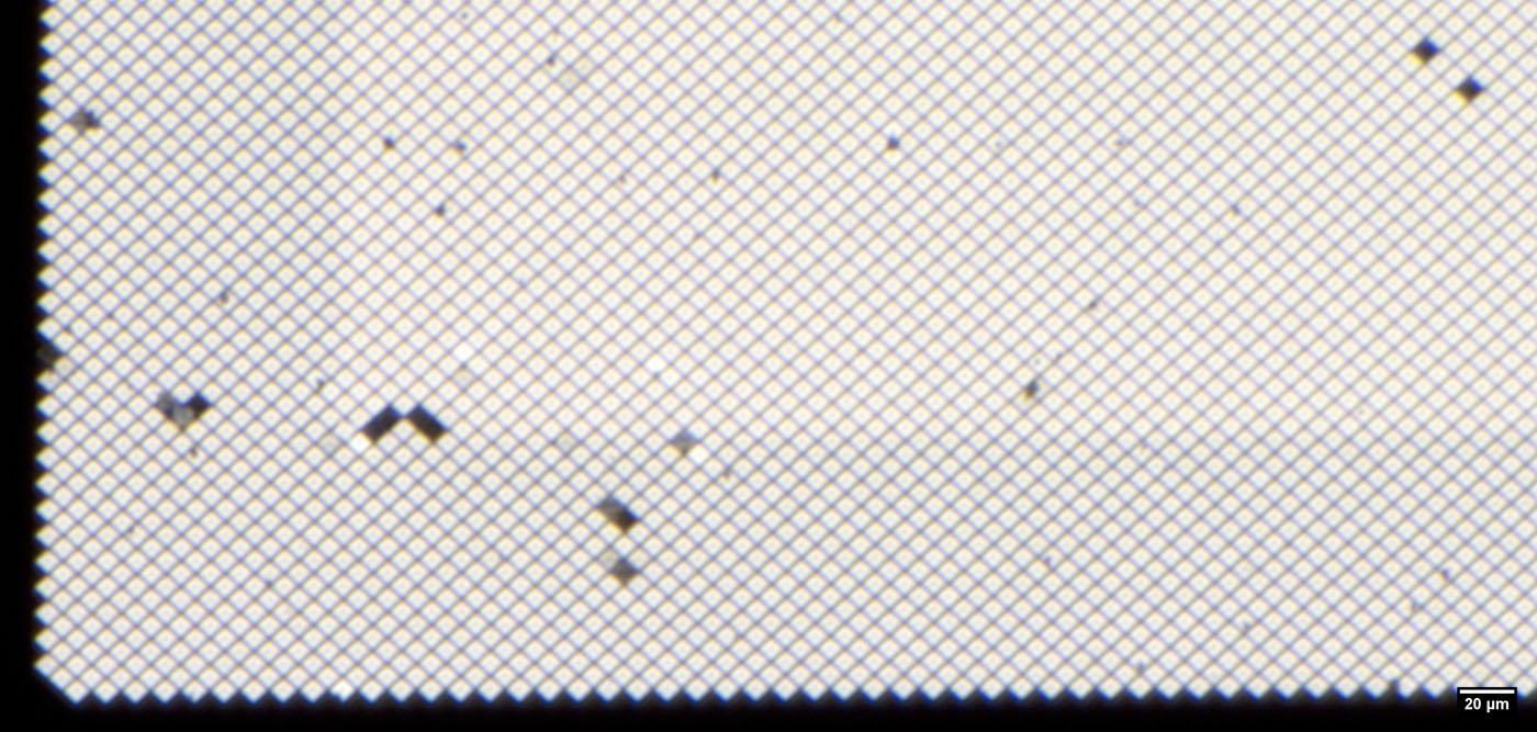
The mirror elements can just be resolved.


At the bottom edge there are some test structures. The left element contains some mirror elements. The area to the right of it could represent the underlying structures.
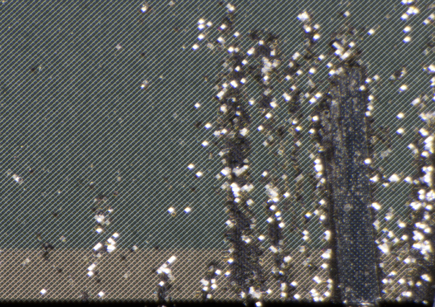
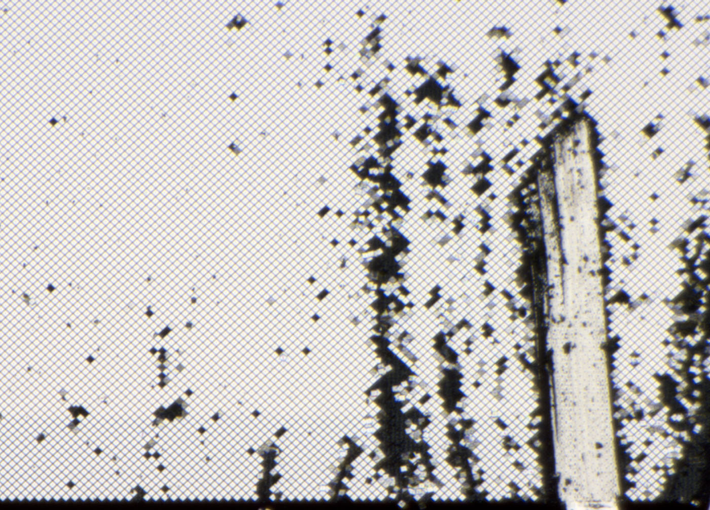
The damaged areas still allow a slightly different view on the mirror elements and the underlying structures.
https://www.richis-lab.de/MEMS_10.htm 