Author Topic: Optoelectronics - die pictures  (Read 18667 times)

0 Members and 2 Guests are viewing this topic.

Offline NoopyTopic starter

  • Super Contributor
  • ***
  • Posts: 1734
  • Country: de
    • Richis-Lab
Re: Optoelectronics - die pictures
« Reply #75 on: July 27, 2023, 07:17:52 pm »


Here you can see the receiver module of the Optobus system from Motorola. The housing is constructed in exactly the same way as the associated transmitter module. It consists of a translucent polymer and has six pins on both sides.


The photodiode array itself is located on the back of the housing. It is protected against environmental influences with a silicone gel.


As with the associated transmitter module, there is a second polymer with a different refractive index in the housing material that represents the light guides.


In case of the transmitter module, the light guides were 40µm high, 50µm wide at the top edge and 80µm wide at the bottom edge. Here, the light guides are 90µm high and 90µm to 130µm wide. The IEEE article "Parallel Optical Interconnects Using VCSELs" explains that increasing the cross-section from the transmitting module through the fiber optic line to the receiving module reduces losses.

In contrast to the transmitting module, the receiving module in addition has a round element with a diameter of 10µm inside the light guides. Perhaps this is intended to suppress certain modes.


With a slightly different illumination, it seems like the ends of the light guides are somewhat smoother than the rest of the surface.


The lead frame appears to be of the same design on both the transmitter and receiver. Two times wires lead to the rear surface of the housing. Two pins conduct the reference potential to the rear surface in a second plane.


At the rear end of the housing, the ten light guides terminate between a ground strip and the ten contacts for forwarding the signals of the photodiodes.


The larger cross-section of the light guides compared to the transmitter module is clearly visible.


On the back of the housing, the small round element in the center of the square light guides is no longer visible.


The photodiode array consists of two elements. The dimensions are 1,2mm x 0,6mm each.


The silicone gel is difficult to remove. The photodiodes are shown as square elements. The IEEE article "OPTOBUS I: Performance of a 4 Gb/s Optical Interconnect" describes that the photodiodes are GaAs PIN photodiodes. Their sensitivity is given as 0.45A/W.


https://www.richis-lab.de/Opto22.htm

 :-/O
 
The following users thanked this post: RoGeorge, PartialDischarge, ch_scr

Offline NoopyTopic starter

  • Super Contributor
  • ***
  • Posts: 1734
  • Country: de
    • Richis-Lab
Re: Optoelectronics - die pictures
« Reply #76 on: August 27, 2023, 12:55:37 pm »


The TSL230 is a light to frequency converter from Texas Instruments. The device generates a clock signal whose frequency is proportional to the illumination intensity. A transparent housing material was used so that the light can penetrate to the circuit. It allows a clear view of the lead frame, the integrated circuit and the bondwires. The marking is on the underside of the housing.


The datasheet shows the configurability of the TSL230. The sensitivity can be set via pins S0/S1. In the least sensitive setting, the device outputs a frequency of 1kHz at an illuminance of 100µW/cm². The maximum clock is 1MHz. The sensitivity can be increased by a factor of 100. In addition, the frequency can be divided down via pins S2/S3.


A matrix with 10x10 square photodiodes occupies a large part of the dies' surface. A metal layer protects the surrounding circuit against light, which could lead to unwanted and uncontrollable failure states.

There are five testpads on the left edge. It´s possible that some kind of tuning is done through this pads. If you assign the bondpads to their functions, you can guess the push-pull output stage in the lower left corner. The line-shaped structures on the right edge indicate that standard cell logic is located there.


E0C231B appears to be an internal designation of the component. The copyright refers to the year 1993.


The photodiodes show their maximum sensitivity in the wavelength range between 750nm and 800nm. Towards longer wavelengths the sensitivity drops very sharply. At 1100nm the TSL230 no longer reacts at all. At 400nm the sensitivity is still 40%. This behaviour is typical for silicon-based photodiodes.


https://www.richis-lab.de/Opto23.htm

 :-/O
 
The following users thanked this post: Swake, TurboTom, _Wim_, RoGeorge, ch_scr, rteodor

Offline MegaVolt

  • Frequent Contributor
  • **
  • Posts: 917
  • Country: by
Re: Optoelectronics - die pictures
« Reply #77 on: September 18, 2023, 11:50:54 am »
I have a damaged DFB laser with 100 mW optical power. The main feature is the ability to tune the laser wavelength by temperature or current.

Photos were taken on a phone :(
 
The following users thanked this post: edavid, TurboTom, RoGeorge, ch_scr

Offline MegaVolt

  • Frequent Contributor
  • **
  • Posts: 917
  • Country: by
Re: Optoelectronics - die pictures
« Reply #78 on: September 18, 2023, 11:52:59 am »
+
 

Offline MegaVolt

  • Frequent Contributor
  • **
  • Posts: 917
  • Country: by
Re: Optoelectronics - die pictures
« Reply #79 on: September 18, 2023, 11:53:35 am »
+
 

Offline MegaVolt

  • Frequent Contributor
  • **
  • Posts: 917
  • Country: by
Re: Optoelectronics - die pictures
« Reply #80 on: September 18, 2023, 11:54:36 am »
+
 

Offline MegaVolt

  • Frequent Contributor
  • **
  • Posts: 917
  • Country: by
Re: Optoelectronics - die pictures
« Reply #81 on: September 18, 2023, 12:05:53 pm »
Most of the elements are installed on a small board. It is most likely ceramic to increase heat dissipation. About 2 W of energy enters the laser and only 0.1 W comes out. The rest goes through the board to the Peltier element located below.

I don’t know what kind of cube is specially marked with a question mark. Most likely this is some kind of focusing system. But I don’t know what kind of material this is and how it works.
 
The following users thanked this post: RoGeorge, ch_scr, Noopy

Offline PartialDischarge

  • Super Contributor
  • ***
  • Posts: 1611
  • Country: 00
Re: Optoelectronics - die pictures
« Reply #82 on: September 18, 2023, 04:30:39 pm »
I don’t know what kind of cube is specially marked with a question mark. Most likely this is some kind of focusing system. But I don’t know what kind of material this is and how it works.

It's an optical isolator that works by faraday rotation, the square in the outside is a magnet.
 
The following users thanked this post: MegaVolt, Noopy

Offline MegaVolt

  • Frequent Contributor
  • **
  • Posts: 917
  • Country: by
Re: Optoelectronics - die pictures
« Reply #83 on: September 20, 2023, 04:17:59 pm »
Today was not a good day :(

Here's a new laser.
 
The following users thanked this post: edavid, ch_scr

Offline MegaVolt

  • Frequent Contributor
  • **
  • Posts: 917
  • Country: by
Re: Optoelectronics - die pictures
« Reply #84 on: September 20, 2023, 04:19:38 pm »
.
 

Offline MegaVolt

  • Frequent Contributor
  • **
  • Posts: 917
  • Country: by
Re: Optoelectronics - die pictures
« Reply #85 on: September 20, 2023, 04:26:22 pm »
.
 

Offline NoopyTopic starter

  • Super Contributor
  • ***
  • Posts: 1734
  • Country: de
    • Richis-Lab
Re: Optoelectronics - die pictures
« Reply #86 on: December 11, 2023, 08:56:16 pm »


The American company Intense develops semiconductor lasers. The module shown here with the name 1050 is the most powerful laser from the 1000 product family. At 2V and 6,5A, the module delivers a wavelength of 808nm with an optical power of 5W. The so-called HHL housing has its optical window on the top.


Thanks to the relatively large window in the housing, you can already see quite a lot of the internal structure.


The cover is welded to the housing. If you grind the edges until the lid is loose, you will see a step on the underside. This step could have served as a positioning aid for the lid.


The optical window appears to have been attached to the lid with solder. A round structure can be seen on the inside. This could be a coating that optimizes the optical properties.


A large part of the housing volume is taken up by a metal block.The metal block represents a large thermal capacity and thus dampens temperature fluctuations. With laser diodes, it is important to keep the temperature as constant as possible. Temperature fluctuations influence the efficiency and the wavelength of the emitted light. The metal cuboid also serves as a heat spreader and thus improves heat dissipation to the backside of the housing.

On closer inspection, you can see that there are two elements. A much flatter carrier is soldered onto a larger cuboid. There is a spacer in the right-hand gap between the cuboid and the housing.

A line is engraved on the surface of the carrier. A circle is engraved on the small metal element that ultimately carries the laser diode. Both structures are most likely used to align the laser correctly.


Only three of the nine pins are connected. One pin supplies the laser diode, one pin contacts the metal block and thus serves as a return conductor. The third pin is connected directly to the housing. The other pins are required if active cooling is integrated into the housing, as is the case with the VQ150 (https://www.richis-lab.de/Opto17.htm).


The relatively large laser diode and a ceramic plate, which serves as a contact surface, are located on the small metal block. To transmit the maximum current of 6,5A, twelve bondwires connect the two plates.


The laser diode is 1,00 mm wide and 0,10 mm high. The beam exit is polished bright.


https://www.richis-lab.de/Opto24.htm

 :-/O
 
The following users thanked this post: RoGeorge, ch_scr

Offline NoopyTopic starter

  • Super Contributor
  • ***
  • Posts: 1734
  • Country: de
    • Richis-Lab
Re: Optoelectronics - die pictures
« Reply #87 on: March 27, 2024, 01:39:21 pm »


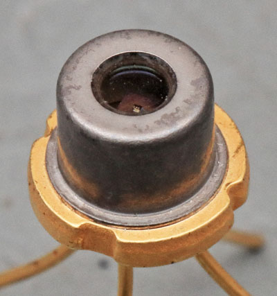
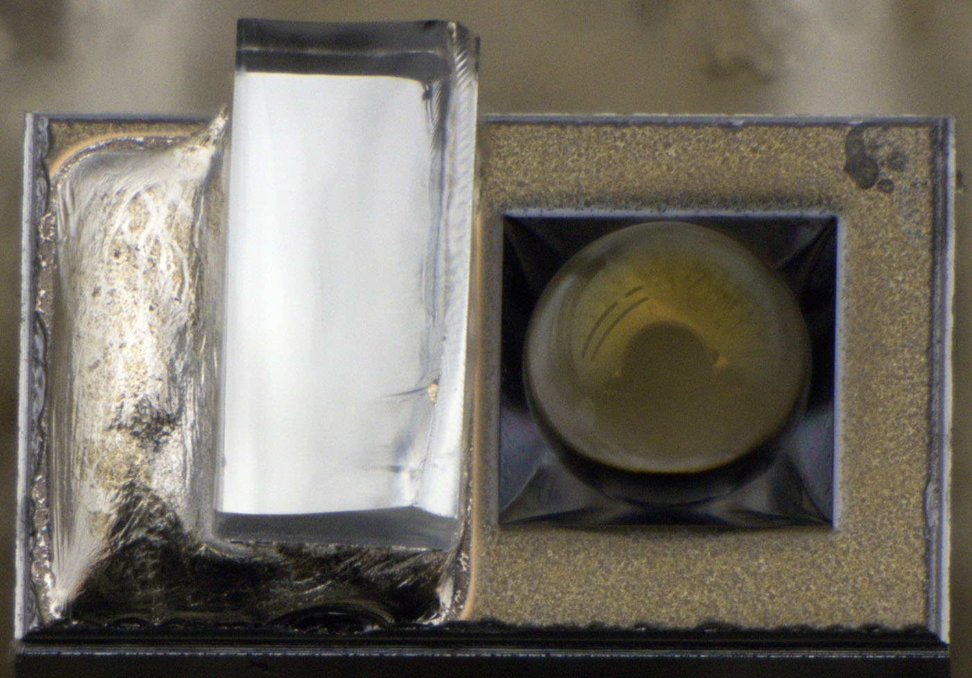
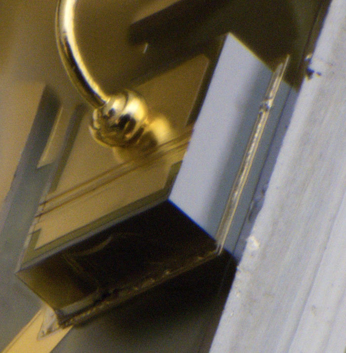
Here you can see a laser module manufactured by Siemens. It is designed to couple a light output of up to 10mW with a wavelength of 1330nm into a glass fiber.


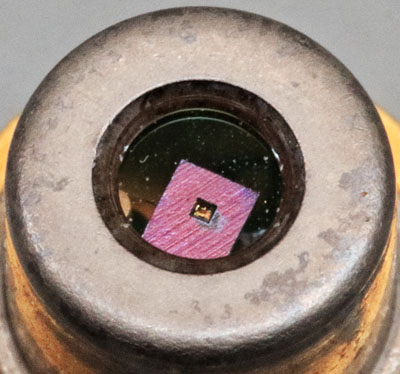
The optical window allows a view inside the package. The structures that can be seen there appear unusual for a laser diode at first glance.


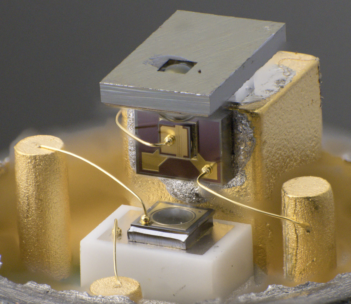
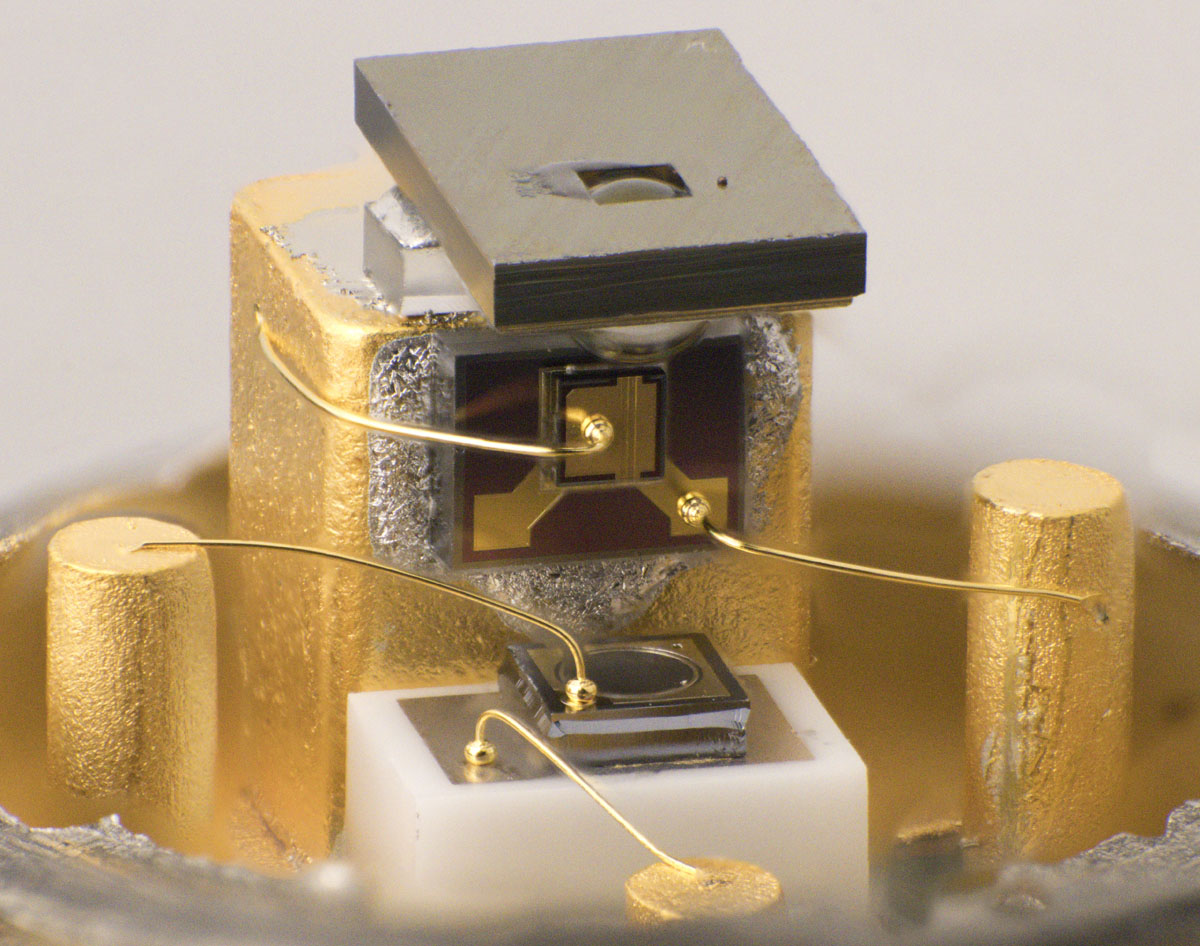
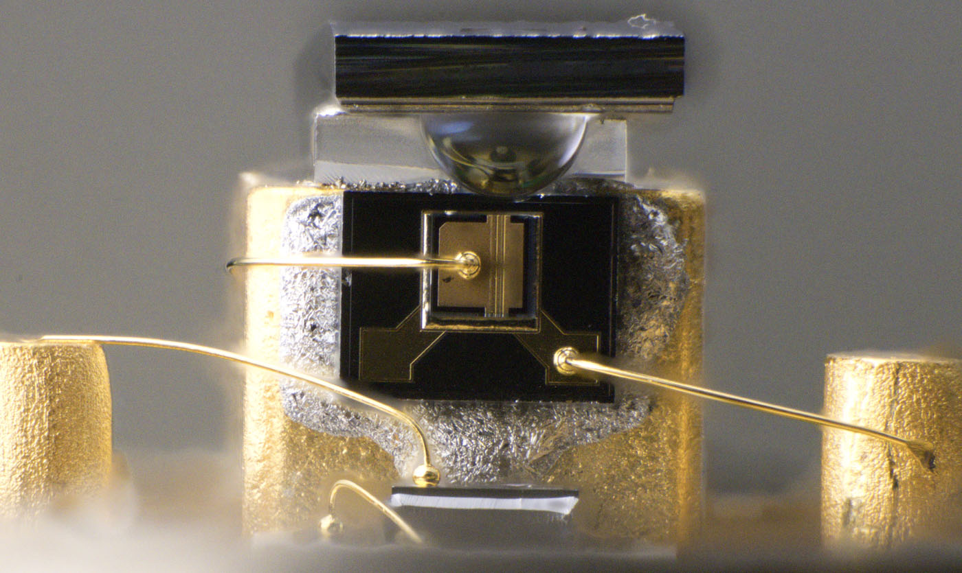
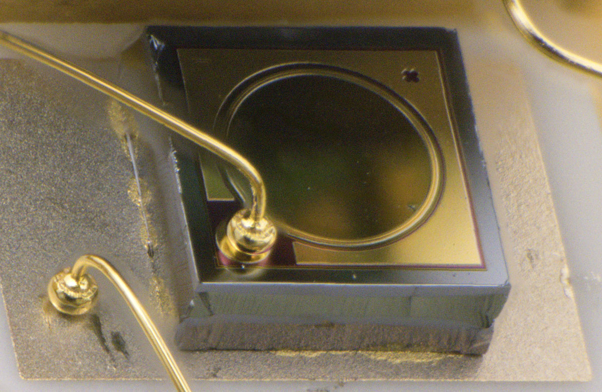
If you open the package, it becomes clear what the top element is. The strip is a carrier for a lens that improves the coupling of the laser light into the glass fiber. A similar element is connected directly to the glass fiber in the IR-LED VQ130 (
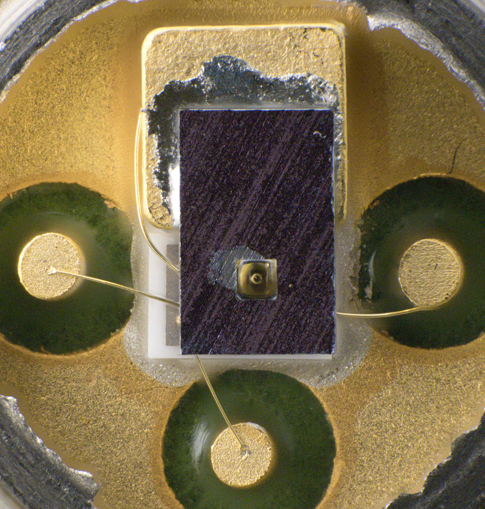
https://www.richis-lab.de/Opto16.htm#Linse). The actual laser diode is located under the lens and a photodiode is placed underneath, which makes it possible to determine the current light output. In contrast to the low-cost laser module (https://www.richis-lab.de/Opto20.htm), the photodiode is insulated from the housing with a ceramic carrier.


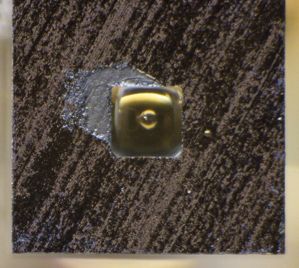
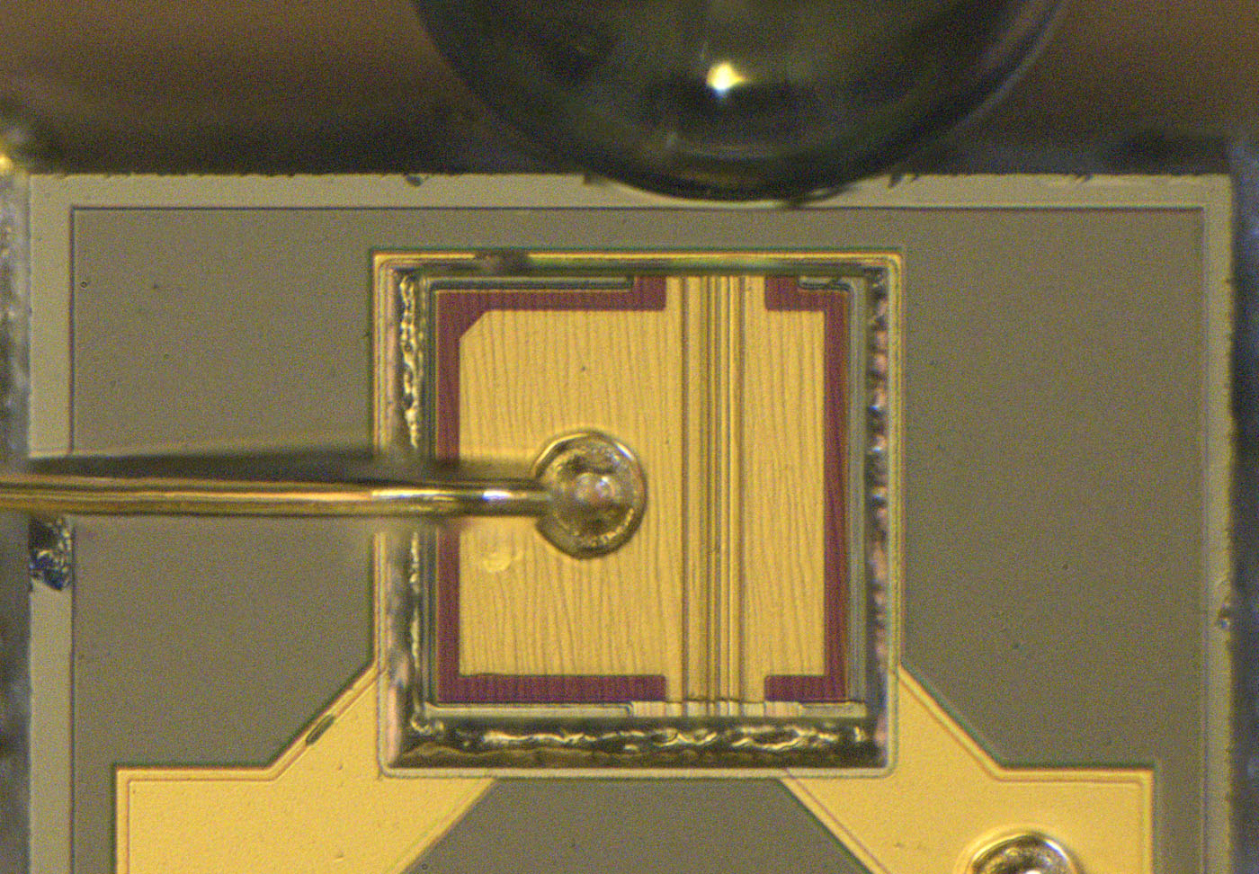
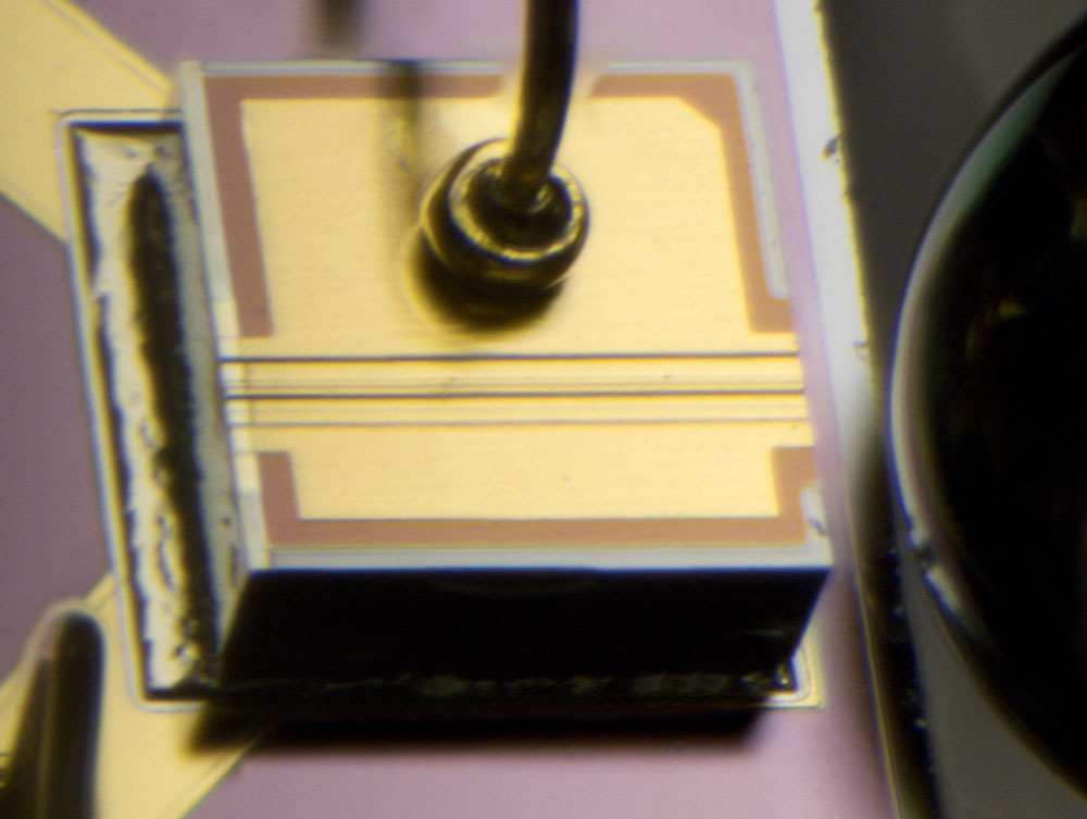
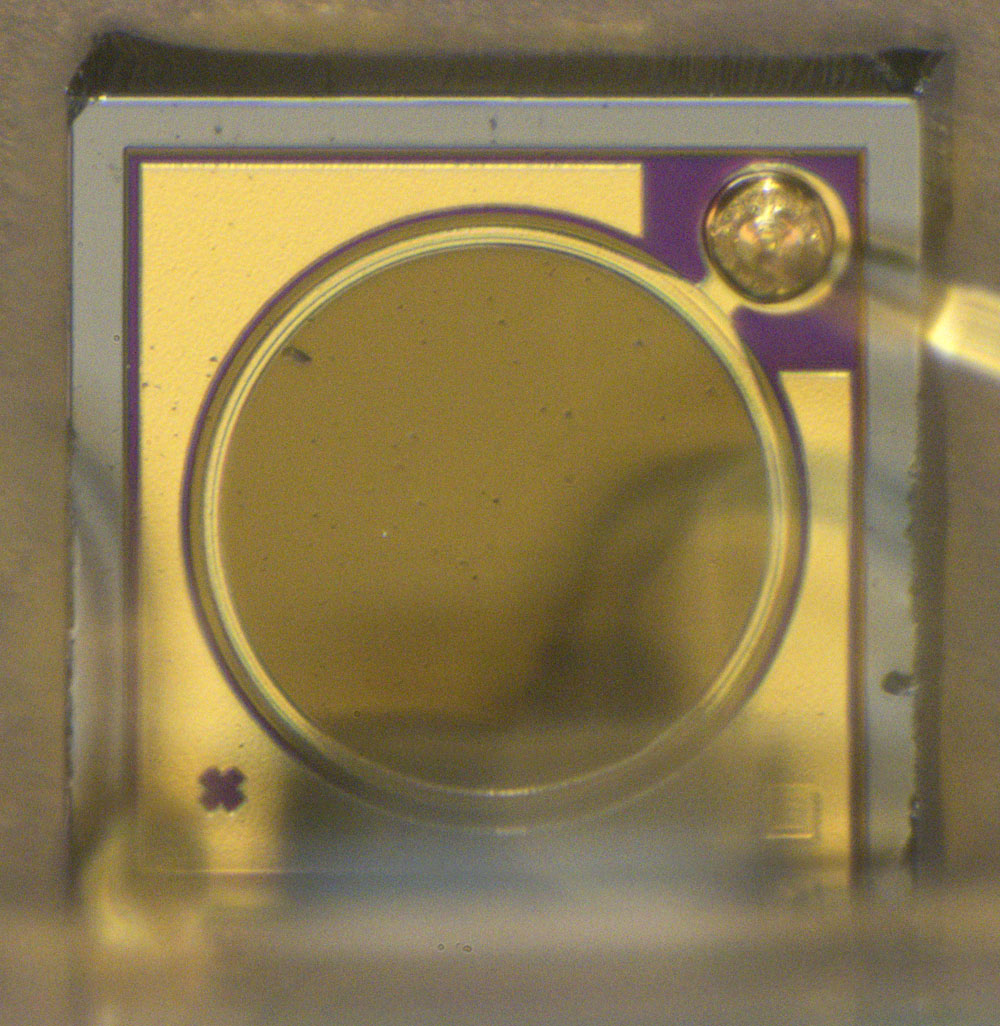
The carrier of the lens appears to be made of silicon. The square through which the laser beam emerges has an edge length of 0,27 mm.


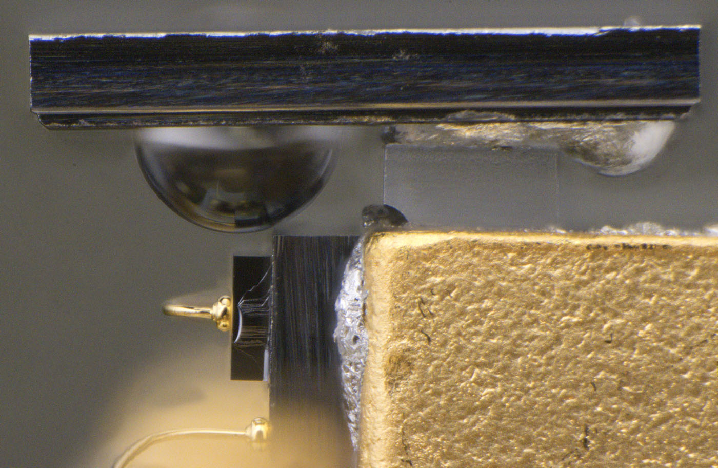
The lens carrier is attached to the protruding element of the package with a transparent block, which also carries the laser diode. The distance between the lens and the laser diode is just 30µm.


The lens has a diameter of 0,5 mm and was inserted from below into an indentation in the carrier.


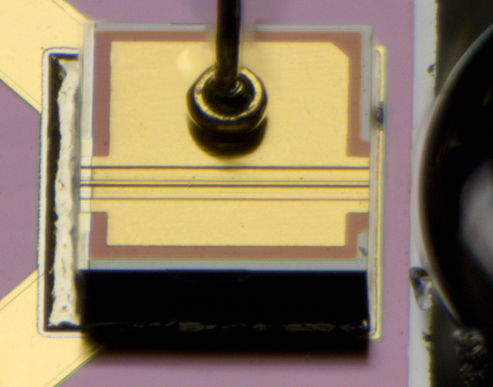
The laser diode is a typical edge emitter. It is located on a carrier and has an edge length of 0,3 mm. The laser diode in the low-cost laser module (https://www.richis-lab.de/Opto20.htm) has a smooth surface and generates the laser beam on the underside. The laser diode shown here is more similar to the laser diodes in the Kyocera 910-00011-IT (https://www.richis-lab.de/Opto14.htm), where the laser channel is visible on the upper side. It is a 40µm wide structure. At higher currents, as in the Kyocera module, the current is usually supplied and drained via the metal layer. In this case, the metal layer only represents one potential of the supply voltage and the circuit is closed via the substrate.


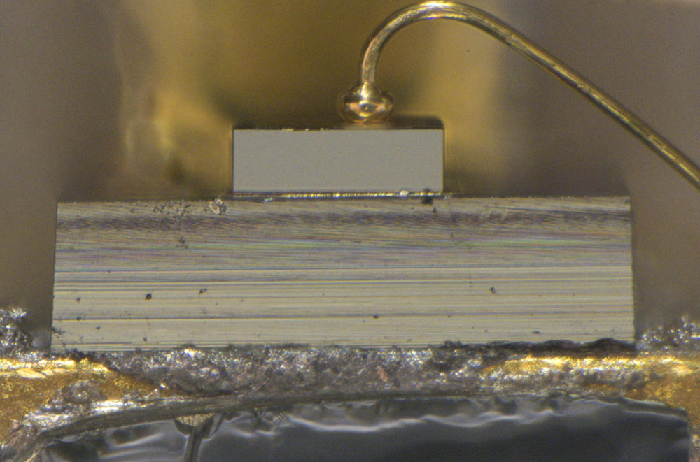
While the sides of the laser diode have broken edges, the front is polished so that the laser light can escape as efficiently as possible. This is clearly evident when compared to the surface structure of the carrier.


The lower side of the laser diode is difficult to image. It appears to be very smooth, which is only logical as it is the second reflective surface of the laser. In the area of the laser structures, a bright layer extends beyond the edge. It remains unclear what the purpose of this layer is.


A small part of the laser light leaves the laser diode at the rear end and hits the photodiode placed there. The current flow through the photodiode can be used to determine the current output power of the laser.


https://www.richis-lab.de/Opto25.htm

 :-/O
 
The following users thanked this post: Vgkid, RoGeorge, iMo, magic

Offline PartialDischarge

  • Super Contributor
  • ***
  • Posts: 1611
  • Country: 00
Re: Optoelectronics - die pictures
« Reply #88 on: March 27, 2024, 04:49:45 pm »
Its strange that the photodetector is not tilted to prevent (or reduce) backreflections to the laser, which leads me to believe that the extra layer on the back side of the laser is a coated filter (like a mirror) to prevent this backreflection.
« Last Edit: March 27, 2024, 04:54:19 pm by PartialDischarge »
 
The following users thanked this post: Noopy

Offline NoopyTopic starter

  • Super Contributor
  • ***
  • Posts: 1734
  • Country: de
    • Richis-Lab
Re: Optoelectronics - die pictures
« Reply #89 on: March 27, 2024, 06:56:56 pm »
I think you have a point. I didn't see a tilting of the photodiode either. Perhaps they found a solution to block reflected light.  :-+


Share me

Digg  Facebook  SlashDot  Delicious  Technorati  Twitter  Google  Yahoo
Smf