Author Topic: Questions about TRIAC  (Read 28025 times)

0 Members and 2 Guests are viewing this topic.

Offline hkBattousaiTopic starter

  • Regular Contributor
  • *
  • Posts: 117
  • Country: 00
Questions about TRIAC
« on: March 17, 2015, 10:41:52 pm »
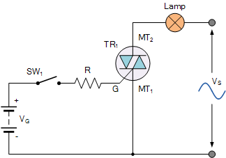
I am trying to understand function of TRIAC. Can you please answer my questions about it?

1. Are the MT1 and MT2 terminal interchangeable? Will the circuit work if I flip the TRIAC so that MT1 and MT2 change places, or I move the triggering circuit between the gate and MT2 terminal? Is the semiconductor structure symmetrical?

2. Assume that I send a very narrow pulse (wide enough to trigger it) to the gate of the TRIAC by means of momentarily closing the switch at 30o angle of the mains supply. At what angle will the TRIAC turn off?

3. What is the difference between "holding current" and "latching current" that I see in datasheets (ex #1, ex #2)?

4. If TRIAC is turned on by gate current, why do datasheets give a "trigger voltage" value? What is "non-trigger voltage"?

5. Does the driving current only circulate through the gate to MT1 (like in MOSFETs and BJTs), or does it sometimes (according to the angle of the AC) circulate from the gate to MT2 as well?

6. If the answer to the question #2 is "180o", what is the simplest solution of keeping the TRIAC on until it reaches 360o?

7. Would the answer to question #2 change if the alternating voltage source waveform was square (consider its sharp zero crossings)?

8. Will the circuit still work if the lamp is replaced by an electric motor or a capacitive load?

9. Can I turn any TRIAC off by applying negative voltage to the gate (i.e.; reverse current)?


Online moffy

  • Super Contributor
  • ***
  • Posts: 3028
  • Country: au
Re: Questions about TRIAC
« Reply #1 on: March 17, 2015, 10:59:32 pm »
1. According to the datasheet you can trigger the gate relative to MT2.
2. It will turn off when the current through the device falls below the holding current, normally you take it as zero.
3. Latching current is the minimum guaranteed current the triac needs to go from off to on. It is momentary. Holding current is the minimum guaranteed current needed to keep an already on device on.
4. You have to overcome that minimum voltage. If you had a current that couldn't overcome the trigger voltage it would not fire.
5. Triacs have a rather complicated firing regime based upon quadrants. Read the data sheet.
6. You trigger it for each half cycle.
7. You need a zero current crossing to turn a triac off.
8. They don't like capacitive, you normally have to place a resistive load in parrallel to ensure that both the latching and holding current conditions are met. Motor/Inductive, similar issue but less so.
9. NO.
 

Offline Zero999

  • Super Contributor
  • ***
  • Posts: 22422
  • Country: gb
  • 0999
Re: Questions about TRIAC
« Reply #2 on: March 17, 2015, 11:27:52 pm »
1. According to the datasheet you can trigger the gate relative to MT2.
I'd question whether that's a mistake in the datasheet. Normally the gate voltage/current is with respect to MT1.
 

Online moffy

  • Super Contributor
  • ***
  • Posts: 3028
  • Country: au
Re: Questions about TRIAC
« Reply #3 on: March 18, 2015, 01:03:30 am »
Had my doubts too, maybe MT2 is MT1?
 

Offline Andy Watson

  • Super Contributor
  • ***
  • Posts: 2340
Re: Questions about TRIAC
« Reply #4 on: March 18, 2015, 01:30:25 am »
1. According to the datasheet you can trigger the gate relative to MT2.
I think the datasheet is indicating which quadrant the device is operating in - because you would expect different gate sensitivity depending on the quadrant. E.g.  MT2 positive with a negative going gate takes more current to latch than other combinatios, etc..
 

Offline hkBattousaiTopic starter

  • Regular Contributor
  • *
  • Posts: 117
  • Country: 00
Re: Questions about TRIAC
« Reply #5 on: March 18, 2015, 09:13:32 pm »
Thank you for answering my question. I think I understand this semiconductor device now.

Here is my first TRIAC circuit. Please tell me if I did anything wrong.


This circuit will control a heating mechanism. L-N are mains terminals. VCC-GND grid is isolated from the PWM signal which comes from a microcontroller. The datasheet says the TRIAC may require up to 35mA gate current to trigger, so I added a totem pole pair to remove stress from the optocoupler. The switching speed will be quite low; one time in a second at most. I hope it works.
 

Offline Zero999

  • Super Contributor
  • ***
  • Posts: 22422
  • Country: gb
  • 0999
Re: Questions about TRIAC
« Reply #6 on: March 20, 2015, 09:11:17 am »
Lots of those components are unnecessary.

QH and QL aren't needed. The opto-coupler should be able to provide enough current to trigger the TRIAC. If there are any doubts then an extra transistor could be added to the opto-coupler, forming a Darlington pair but it shouldn't be necessary.

I notice the 5V supply is connected to the mains so it needs to be treated with the same respect as the mains.

Is the 3.3V rail isolated from the 5V rail and the mains? If not then there's no point in using an opto-coupler. You might as well trigger the TRIAC directly from the microcontroller.

I also hope you're aware that the PWM frequency needs to be substantially lower than the mains frequency to work.


Offline hkBattousaiTopic starter

  • Regular Contributor
  • *
  • Posts: 117
  • Country: 00
Re: Questions about TRIAC
« Reply #7 on: March 20, 2015, 09:17:52 am »
QH and QL aren't needed. The opto-coupler should be able to provide enough current to trigger the TRIAC. If there are any doubts then an extra transistor could be added to the opto-coupler, forming a Darlington pair but it shouldn't be necessary.

The TRIAC requires minimum 2mA and maximum 35mA current to be triggered. Yes, the optocoupler can give that much current, but it also needs high driving forward current for that. That will reduce its life time. By adding QH and QL, I reduced the stress on it.

Is the 3.3V rail isolated from the 5V rail and the mains? If not then there's no point in using an opto-coupler. You might as well trigger the TRIAC directly from the microcontroller.

There is a transformer which gives two isolated isolated windings (no center-tap, they are unconnected). I use one of them to generate 3.3V, and the other one for the 5V supply.
 

Offline Zero999

  • Super Contributor
  • ***
  • Posts: 22422
  • Country: gb
  • 0999
Re: Questions about TRIAC
« Reply #8 on: March 20, 2015, 10:22:14 am »
QH and QL aren't needed. The opto-coupler should be able to provide enough current to trigger the TRIAC. If there are any doubts then an extra transistor could be added to the opto-coupler, forming a Darlington pair but it shouldn't be necessary.

The TRIAC requires minimum 2mA and maximum 35mA current to be triggered. Yes, the optocoupler can give that much current, but it also needs high driving forward current for that. That will reduce its life time. By adding QH and QL, I reduced the stress on it.
I took it as it the maximum allowed current into the trigger terminal is 35mA but the minimum current required to trigger is 2mA.

Either way, there is no need for QL. If anything it'll make it worse. It will never conduct. TRIACs aren't like MOSFETS.  They don't have a gate capacitance to discharge.

Quote
Is the 3.3V rail isolated from the 5V rail and the mains? If not then there's no point in using an opto-coupler. You might as well trigger the TRIAC directly from the microcontroller.

There is a transformer which gives two isolated isolated windings (no center-tap, they are unconnected). I use one of them to generate 3.3V, and the other one for the 5V supply.
How well isolated is the 3.3V and 5V output?

It's pretty likely there isn't enough insulation between the secondary windings to act as protection against electric shock.

The secondary windings are normally on a separate bobbin to the primary winding or have a thick layer of insulating tape between them which provides enough insulation to protect against shock.

The chances are, the only insulation between each secondary winding is just the thin enamel on the wire. This is only classed as functional insulation and is not to be relied upon for protection against electric shock.

Why not use an optically isolated TRIAC?

http://www.ti.com/lit/ds/symlink/moc3022.pdf
http://www.farnell.com/datasheets/1688212.pdf
http://www.vishay.com/docs/83627/il410.pdf

I also hope you're aware of the minimum distance required on a PCB between the mains and extra low voltage side?
 

Offline hkBattousaiTopic starter

  • Regular Contributor
  • *
  • Posts: 117
  • Country: 00
Re: Questions about TRIAC
« Reply #9 on: March 20, 2015, 02:53:40 pm »
QH and QL aren't needed. The opto-coupler should be able to provide enough current to trigger the TRIAC. If there are any doubts then an extra transistor could be added to the opto-coupler, forming a Darlington pair but it shouldn't be necessary.

The TRIAC requires minimum 2mA and maximum 35mA current to be triggered. Yes, the optocoupler can give that much current, but it also needs high driving forward current for that. That will reduce its life time. By adding QH and QL, I reduced the stress on it.
I took it as it the maximum allowed current into the trigger terminal is 35mA but the minimum current required to trigger is 2mA.

Please check my first post on this thread. There is a screen shot from the TRIAC datasheet. It lists the minimum and maximum currents to trigger the gate. I think that's a "minimax". I understand it like this, if I want to trigger the TRIAC, the gate current should be above 35mA. And, if I want it to stay turned off, it has to stay below 2mA.

Either way, there is no need for QL. If anything it'll make it worse. It will never conduct. TRIACs aren't like MOSFETS.  They don't have a gate capacitance to discharge.

Is it correct like this?


Quote
Is the 3.3V rail isolated from the 5V rail and the mains? If not then there's no point in using an opto-coupler. You might as well trigger the TRIAC directly from the microcontroller.

There is a transformer which gives two isolated isolated windings (no center-tap, they are unconnected). I use one of them to generate 3.3V, and the other one for the 5V supply.
How well isolated is the 3.3V and 5V output?

It's pretty likely there isn't enough insulation between the secondary windings to act as protection against electric shock.

The secondary windings are normally on a separate bobbin to the primary winding or have a thick layer of insulating tape between them which provides enough insulation to protect against shock.

The chances are, the only insulation between each secondary winding is just the thin enamel on the wire. This is only classed as functional insulation and is not to be relied upon for protection against electric shock.

The datasheet says that the insulation is for 4kV. But it doesn't mention whether it is only between primary and secondary windings, or between every winding. I have to find a solid solution for that. Maybe I can use two separate transformers. It is good that you pointed this out.

Why not use an optically isolated TRIAC?

http://www.ti.com/lit/ds/symlink/moc3022.pdf
http://www.farnell.com/datasheets/1688212.pdf
http://www.vishay.com/docs/83627/il410.pdf

I will control a 2kW heater. Actually, I'm trying to design a reflow oven controller for my personal usage. I browsed the list of optotriacs, none of them can switch more than 1A continuous current.

I also hope you're aware of the minimum distance required on a PCB between the mains and extra low voltage side?

I will take care of it when I come to the PCB design stage.


Thank you for your warnings and suggestions Hero999. You helped me a lot.
 

Offline eneuro

  • Super Contributor
  • ***
  • Posts: 1562
  • Country: 00
Re: Questions about TRIAC
« Reply #10 on: March 20, 2015, 05:57:15 pm »
I will control a 2kW heater.
Do you have additional current sensing and zero crossing circuit? Switchin 2kW in AC voltage maximum (random phase) with less than 1A gate currect, I do not know, but probably wouldn't be happy with such design, especially when ZVC costs nothing using MOC304x   ???
  with Zero Voltage Crossing triac driver 2x 180 Ohm resistors optionally another one and varistor with fuse in circuit similar to this one from datasheet above works nice for me in a few projects where no phase control needed ;)

Anyway be carefull when playing with triacs TAP (pin 4 in datasheet below) while this BTA16 has insulated this tap, but NOT ALL triacks has this tap insulated, so never good idea trying to check radiator temperature just by touching mains powered triac taps.
http://www.onsemi.com/pub_link/Collateral/BTA16-600BW3-D.PDF

« Last Edit: March 20, 2015, 06:05:14 pm by eneuro »
12oV4dWZCAia7vXBzQzBF9wAt1U3JWZkpk
“Let the future tell the truth, and evaluate each one according to his work and accomplishments. The present is theirs; the future, for which I have really worked, is mine”  - Nikola Tesla
-||-|-
 

Offline Zero999

  • Super Contributor
  • ***
  • Posts: 22422
  • Country: gb
  • 0999
Re: Questions about TRIAC
« Reply #11 on: March 20, 2015, 09:30:59 pm »
Either way, there is no need for QL. If anything it'll make it worse. It will never conduct. TRIACs aren't like MOSFETS.  They don't have a gate capacitance to discharge.

Is it correct like this?
That's better.

Quote
The datasheet says that the insulation is for 4kV. But it doesn't mention whether it is only between primary and secondary windings, or between every winding. I have to find a solid solution for that. Maybe I can use two separate transformers. It is good that you pointed this out.
There's no way that transformer will have sufficient insulation between the secondary windings for protection against electric shock.

It will look something like this under all of the resin.

The two secondary windings will just be wound on top of one another. This is fine for functional insulation but it won't protect you from electric shock if one of the secondary windings is connected to the mains: a voltage spike can easily cause the thin lacquer insulation to break down.


I will control a 2kW heater. Actually, I'm trying to design a reflow oven controller for my personal usage. I browsed the list of optotriacs, none of them can switch more than 1A continuous current.
Opto-TRIACs aren't designed to directly switch the mains. The idea is to use the opto-TRIAC to trigger a larger TRIAC, as shown in the circuit posted by eneuro.


Quote
I will take care of it when I come to the PCB design stage.
For reinforced insulation, i.e. what's needed between the DC side if it's not connected to earth and the mains, the creapage distance is 6.4mm and clearance is 4mm. This means the primary to secondary track spacing needs to be at least 6.4m, unless there's a slot in the PCB separating them, in which case it's 4mm.
http://www.smps.us/pcbtracespacing.html
http://www.silabs.com/Support%20Documents/TechnicalDocs/AN583.pdf
 

Offline Alex Eisenhut

  • Super Contributor
  • ***
  • Posts: 3728
  • Country: ca
  • Place text here.
Hoarder of 8-bit Commodore relics and 1960s Tektronix 500-series stuff. Unconventional interior decorator.
 

Offline eneuro

  • Super Contributor
  • ***
  • Posts: 1562
  • Country: 00
Re: Questions about TRIAC
« Reply #13 on: March 20, 2015, 10:52:37 pm »
PCB design stage? This is a commodity item.
Yep, if you connect it to MPU using... h-bridge and DC motor to drive potentiometer  :-DD

If you can buy it for 3$ on eBay, why design it?
Because of this is electronics forum, not ladies looking for another toy?  ;D
« Last Edit: March 20, 2015, 10:58:16 pm by eneuro »
12oV4dWZCAia7vXBzQzBF9wAt1U3JWZkpk
“Let the future tell the truth, and evaluate each one according to his work and accomplishments. The present is theirs; the future, for which I have really worked, is mine”  - Nikola Tesla
-||-|-
 

Offline rs20

  • Super Contributor
  • ***
  • Posts: 2323
  • Country: au
Re: Questions about TRIAC
« Reply #14 on: March 20, 2015, 11:04:26 pm »
Yikes, it's freakin' scary how you have "GND"and "N" just wired together like that. I assume you know that connecting mains earth and mains neutral together is a huge no-no -- so what does the GND mean? The negative of a transformer secondary? The actual design considerations (poor isolation between secondaries) has already been discussed above, I'm just here to strongly recommend that you rename "GND" and "VCC" to, respectively, "N" and "N+5V", or similar. Except of course, you would just delete the ground because there's already an N there. I know it doesn't translate to anything different in the real, constructed circuit, but I think it's important for diagrams to clearly indicate whether nodes are earth-or-neutral referenced. Otherwise you'll get killed if you relying on just remembering these details when you mod this circuit in 2 years. ("Where should I clip the ground of my oscilloscope probe? Ah look! Ground!" BANG). I'm surprised this hasn't been mentioned by others, am I overreacting? Tell me if so.

I strongly endorse eneuro's suggestion. AFAIK, that is the "proper"/standard way of controlling mains with an isolated micro, and it completely does away with the need for a separate transformer/power supply. A very elegant solution. Eneuro's solution repeated below:


« Last Edit: March 20, 2015, 11:09:50 pm by rs20 »
 

Offline Alex Eisenhut

  • Super Contributor
  • ***
  • Posts: 3728
  • Country: ca
  • Place text here.
Re: Questions about TRIAC
« Reply #15 on: March 20, 2015, 11:05:26 pm »
PCB design stage? This is a commodity item.
Yep, if you connect it to MPU using... h-bridge and DC motor to drive potentiometer  :-DD

If you can buy it for 3$ on eBay, why design it?
Because of this is electronics forum, not ladies looking for another toy?  ;D

 ::)

http://www.ebay.ca/itm/Digital-PID-Temperature-Controller-220V-Max-40A-SSR-K-Thermocouple-Probe-Cable-/121513366229?pt=LH_DefaultDomain_0&hash=item1c4ac2d2d5


Hoarder of 8-bit Commodore relics and 1960s Tektronix 500-series stuff. Unconventional interior decorator.
 

Offline Zero999

  • Super Contributor
  • ***
  • Posts: 22422
  • Country: gb
  • 0999
Re: Questions about TRIAC
« Reply #16 on: March 20, 2015, 11:14:46 pm »
Buying a pre-made PID controller is not a bad idea, especially if you have little experience with designing mains PCBs. It depends on the requirements: if space is a problem then that one looks a little bulky. You may also want other features such as a programmable temperature cycle.
 

Offline Alex Eisenhut

  • Super Contributor
  • ***
  • Posts: 3728
  • Country: ca
  • Place text here.
Re: Questions about TRIAC
« Reply #17 on: March 20, 2015, 11:18:41 pm »
Buying a pre-made PID controller is not a bad idea, especially if you have little experience with designing mains PCBs. It depends on the requirements: if space is a problem then that one looks a little bulky. You may also want other features such as a programmable temperature cycle.

For 22$, is it really worth the risk of messing about with the mains with a home-made kludge?

I know, we're all real men with big hairy chests here (and HUGE biceps full of tattoos) but at some point, you just gotta move on.

If some people are so concerned about how their electronics affects their perception of themselves, perhaps they could design a temperature controller with a hydrogen thyratron, a big one.
Hoarder of 8-bit Commodore relics and 1960s Tektronix 500-series stuff. Unconventional interior decorator.
 

Offline Zero999

  • Super Contributor
  • ***
  • Posts: 22422
  • Country: gb
  • 0999
Re: Questions about TRIAC
« Reply #18 on: March 21, 2015, 02:38:32 pm »
This is for a reflow oven so a simple PID controller is probably not good enough.

Can that PID controller produce a complex temperature profile? Could one interface it with an MCU to achieve that?
 

Offline Alex Eisenhut

  • Super Contributor
  • ***
  • Posts: 3728
  • Country: ca
  • Place text here.
Re: Questions about TRIAC
« Reply #19 on: March 21, 2015, 03:50:04 pm »
This is for a reflow oven so a simple PID controller is probably not good enough.

Can that PID controller produce a complex temperature profile? Could one interface it with an MCU to achieve that?

I'm afraid of answering now because people would think this is me

Hoarder of 8-bit Commodore relics and 1960s Tektronix 500-series stuff. Unconventional interior decorator.
 

Offline hkBattousaiTopic starter

  • Regular Contributor
  • *
  • Posts: 117
  • Country: 00
Re: Questions about TRIAC
« Reply #20 on: March 23, 2015, 02:59:34 pm »
Do you have additional current sensing and zero crossing circuit? Switchin 2kW in AC voltage maximum (random phase) with less than 1A gate currect, I do not know, but probably wouldn't be happy with such design, especially when ZVC costs nothing using MOC304x   ???
  with Zero Voltage Crossing triac driver 2x 180 Ohm resistors optionally another one and varistor with fuse in circuit similar to this one from datasheet above works nice for me in a few projects where no phase control needed ;)
http://www.onsemi.com/pub_link/Collateral/BTA16-600BW3-D.PDF

By the time you posted this message, I didn't know anything about zero crossing optotriacs. Thank you for teaching me this topic.

Here is my circuit with MOC3063:


I redesigned the circuit and chose the circuit element values according to the optotriac datasheet. I hope it is okay now.
 

Offline Zero999

  • Super Contributor
  • ***
  • Posts: 22422
  • Country: gb
  • 0999
Re: Questions about TRIAC
« Reply #21 on: March 23, 2015, 03:35:38 pm »
Looks good to me.
 

Offline paulie

  • Frequent Contributor
  • **
  • !
  • Posts: 849
  • Country: us
Re: Questions about TRIAC
« Reply #22 on: March 23, 2015, 04:38:15 pm »
Me too. Used the same many times for light, heater, and motor control. What an improvement over that old circuit.
 

Offline eneuro

  • Super Contributor
  • ***
  • Posts: 1562
  • Country: 00
Re: Questions about TRIAC
« Reply #23 on: March 23, 2015, 05:15:05 pm »
chose the circuit element values according to the optotriac datasheet.
For 3.3V instead of 100R and 330R I'd probably use 2 x 180R, so at 360R total we get at 1.3Vf input optotriac diode ~5.5mA.
I've additionaly MPU PWM timer interupt set to multiply of full 20ms @ 50Hz  240VAC mais-for fine tune maybe shrter pulses than 1s will be needed  ;)
12oV4dWZCAia7vXBzQzBF9wAt1U3JWZkpk
“Let the future tell the truth, and evaluate each one according to his work and accomplishments. The present is theirs; the future, for which I have really worked, is mine”  - Nikola Tesla
-||-|-
 

Offline rs20

  • Super Contributor
  • ***
  • Posts: 2323
  • Country: au
Re: Questions about TRIAC
« Reply #24 on: March 23, 2015, 10:45:33 pm »
I've additionaly MPU PWM timer interupt set to multiply of full 20ms @ 50Hz  240VAC mais-for fine tune maybe shrter pulses than 1s will be needed  ;)

I can only assume you're criticizing the use of a 1Hz PWM.  Using a 1Hz PWM seems like a fine choice to me:

-- PWM frequency << 50 Hz: You select a bunch of periods, and then skip a bunch, etc. Good power factor, everything works.
-- PWM frequency ~= 50 Hz: If your MPU is not PWMing in lockstep with the mains frequency, you'll get all sorts of terrible beat frequencies.
-- PWM frequency >> 50 Hz: Obviously won't work; the triac will just stay on.


Share me

Digg  Facebook  SlashDot  Delicious  Technorati  Twitter  Google  Yahoo
Smf


-->