-
Hi,
you can have high efficiency and still have voltage droop. That's because of the reactive impedance. i.e. the leakage inductance in a transformer plus the transmission system.
Here is a reference to efficiency of power distribution transformers:
(Attachment Link)
Taken from:
https://documents.hammondpowersolutions.com/documents/Literature/Medium_Voltage_Distribution_Transformers/HPS-Millennium-G-VPI-Brochure.pdf
This is Hammond Power Solutions.
This is only resistive losses, it is not regulation.
Notice how the efficiency improves as at the larger kVAs.
Regards,
Jay_Diddy_B
-
It is commonly specified in terms of percentage. That is the per unit system that power engineers use. You calculate the full load impedance based on the maximum voltage and current and V/I is the base impedance. Then the percent source impedance is the ratio of the base.Oh, and I recall a typical distribution transformer impedance is somewhere around 5%
Impedance is not something that is measured or specified as a percentage.Yeah, technically you're correct
Isn't that pretty much the only kind of correct?
-
drussel, again, I suggest you guys look at Jay_Diddy_B's simulation as well as mine. They both show that a full wave rectified load IN YOUR HOUSE can affect the waveform you measure in your house. Jay_Diddy_B showed a 0.2 amp constant current, unfiltered load (only a capacitor).
I modified that to include a simulation of the utility system including their line and transformer, using real world values.
A load in your house CAN affect the waveform you measure. WILL IT? It depends. Will it affect your neighbor? Maybe. Will the neighbor's load affect you? Maybe. You can't make a general statement.
If your mains is distorted because of your loads and the neighbor's house is across the street and also connected to the pole transformer secondary (ie, low impedance between houses) then it might. And vice versa.
But it all depends on a ton of things.
Based on my tests, apparently my loads are fairly clean and don't, on their own, distort my mains waveform. However, it is distorted with about 5% THD. Which implies it's coming from my neighbors. But the further away (higher impedance) between my house and others, the less likely we will affect each other. But again it depends on a lot of stuff. I could probably go into one of my ATX power supplies, strip out all the filtering, and suddenly get a much more distorted waveform at my wall outlet.
THERE'S NO ALWAYS TRUE, RIGHT ANSWER OTHER THAN WAVEFORM DISTORTION ON YOUR MAINS COULD BE EITHER YOUR OWN FAULT OR THE NEIGHBORS' FAULT OR THE UTILITY'S FAULT. -
Turning off a couple relatively light, probably actually fairly clean PF-wise loads that are fairly well connected via 14ga/12ga wire to your panel which is then connected via typically 6ga or bigger out to a transformer that is well connected to the grid through a relatively low impedance source, very stiff, with massive fault current capability, won't show much difference, even right at your load.
Number 6 AWG wire has a cross-sectional area of 13.3mm^2. In the UK, 16mm^2 square meter tails were grudgingly accepted, for short runs, where the company's fuse was no more than 60A or 80A, but 25mm^2 is preferred, and mandatory for 100A fuses such as I have here. I'm not sure, but I think the latest edition of the wiring regulations makes 25mm^2 mandatory for all domestic installations. UK house mains are low impedance: turning off a couple of local loads isn't going to make much difference. -
Oh, and I recall a typical distribution transformer impedance is somewhere around 5%
Impedance is not something that is measured or specified as a percentage.
No, actually it is. The most commonly specified impedance of a distribution transformer is Z, which is the percentage of the rated voltage that needs to be appled to the primary to cause the rated current to flow in a shorted secondary.
https://www.eaton.com/ecm/groups/public/@pub/@electrical/documents/content/wp009001en.pdf
I'm sorry, you are not technically correct.
-
Impedance is not something that is measured or specified as a percentage.
No, actually it is. The most commonly specified impedance of a distribution transformer is Z, which is the percentage of the rated voltage that needs to be appled to the primary to cause the rated current to flow in a shorted secondary.
Well, yeah, I said that up above in reply #121:I thought that was just used for calculating circulating currents for things like fault-condition calculations, etc, like if you have a 10% 120v transformer, 12v would cause full rated current with a shorted secondary....
...but I'm not a power systems engineer, so I'll let those more knowledgeable in the field chime in here.
Anyway, as pointed out here...you can have high efficiency and still have voltage droop. That's because of the reactive impedance. i.e. the leakage inductance in a transformer plus the transmission system.
It is commonly specified in terms of percentage. That is the per unit system that power engineers use. You calculate the full load impedance based on the maximum voltage and current and V/I is the base impedance. Then the percent source impedance is the ratio of the base.
Yes, I hadn't thought fully about the fact that since the efficiency of large distribution transformers is very high that any significant voltage droop would be caused by the inductive rather than resistive components and thus you can also calculate your expected voltage drop using the "per unit" system with ratios used in distribution-level power systems for everything to account for the differences in sizes and voltages, etc. It makes perfect sense, it's just an aspect that I hadn't thought of since, like I said, I'm not a power engineer.
-
Sorry Joe I never captured them as it was a few years back. This topic has been discussed here before and I can't even be bothered to try to find the threads.......none of the screenshots posted thus far are as bad as some I've seen.......
Tautech, I was hoping to see some of these waveforms you mention.
While some members here can't/won't/don't accept that distorted mains waveforms are a fact of life yet others have proved they are amuses me when the explanations for such seen behaviour is quite simple.
Hell even Simon gets it (no offense) when non-sinusoidal current loads can affect sinusoidal voltages from a NON ZERO impedance supply.
As for providing screenshots of mains, there are plenty here already that clearly show what to expect so despite that I've worked a lot with mains over the years I have NO wish to work with it more than is absolutely necessary and recommend those without sufficient experience don't either.
I have strong views about this if only for the safety of others and reported this thread in its infancy for fear that those attempting to measure/view mains waveforms are exposing themselves to unnecessary risk. -
Sorry Joe I never captured them as it was a few years back. This topic has been discussed here before and I can't even be bothered to try to find the threads.......none of the screenshots posted thus far are as bad as some I've seen.......
Tautech, I was hoping to see some of these waveforms you mention.
While some members here can't/won't/don't accept that distorted mains waveforms are a fact of life yet others have proved they are amuses me when the explanations for such seen behaviour is quite simple.
Hell even Simon gets it (no offense) when non-sinusoidal current loads can affect sinusoidal voltages from a NON ZERO impedance supply.
As for providing screenshots of mains, there are plenty here already that clearly show what to expect so despite that I've worked a lot with mains over the years I have NO wish to work with it more than is absolutely necessary and recommend those without sufficient experience don't either.
I have strong views about this if only for the safety of others and reported this thread in its infancy for fear that those attempting to measure/view mains waveforms are exposing themselves to unnecessary risk.
That's too bad, I would have liked to have seen them as it sounded as though you had seen some abnormal conditions, compared with the typical I see shown here. These few I presented caused problems and I would say they are not what I would consider normal. Certainly, not anything I would expect in a home. Still, it's a good idea to have some understanding of what can happen on the mains.
One day I hope to find someone that understands the cause of that one oddball. -
For those interested in what a fairly highly distorted waveform look like I've included a 10% THDv waveform in the attachment. I also give the harmonic spectrum breakdown for both the voltage and current.
These were taken at a fairly large pumping station in rural Victoria (Oz). These results are taken when I was drawing about 1600 kW from the grid.
-
I don't have any detailed data, but some 25 years ago I was "summoned" to a site of a client of a company I worked for, because "your damned stupid servers are crashing all the time and you better get here and fix it.."".
So boss sends me, I enter large, 20 something story building, enter one of the 3 elevators, go to top floor (where they put their computer room), and after some checking, I realize that someone decided it was a good thing to attach their newly made computer room to a power closet of an elevator engine station with 3 huge elevator motors... At that time, there was no soft start circuits..
So I called my friend who does power stuff, and he comes with power analyser. He said he never saw anything that bad... He said spikes and sags "were worth of their own Greek tragedy..."
After he explained them what they did, they finally cashed out and did it properly.. No problems whatsoever after.. -
Sorry Joe I never captured them as it was a few years back. This topic has been discussed here before and I can't even be bothered to try to find the threads.......none of the screenshots posted thus far are as bad as some I've seen.......
Tautech, I was hoping to see some of these waveforms you mention.
While some members here can't/won't/don't accept that distorted mains waveforms are a fact of life yet others have proved they are amuses me when the explanations for such seen behaviour is quite simple.
Hell even Simon gets it (no offense) when non-sinusoidal current loads can affect sinusoidal voltages from a NON ZERO impedance supply.
As for providing screenshots of mains, there are plenty here already that clearly show what to expect so despite that I've worked a lot with mains over the years I have NO wish to work with it more than is absolutely necessary and recommend those without sufficient experience don't either.
I have strong views about this if only for the safety of others and reported this thread in its infancy for fear that those attempting to measure/view mains waveforms are exposing themselves to unnecessary risk.
That's too bad, I would have liked to have seen them as it sounded as though you had seen some abnormal conditions, compared with the typical I see shown here. These few I presented caused problems and I would say they are not what I would consider normal. Certainly, not anything I would expect in a home. Still, it's a good idea to have some understanding of what can happen on the mains.
One day I hope to find someone that understands the cause of that one oddball.
Joe, which ones are you referring to? And which one is the oddball? I see three jpg's named "fun", and you talk about laying all three phases on top of each other, but I'm not sure I understand.
IMO, the second one is very likely an 8-cycle fault on a remote circuit, which is pretty typical for high speed relay clearing on a power system. So you're just catching the voltage dip due to a remote fault. This kind of trace is extremely common, and happens every time you get a ground fault on a power system line (eg, tree branch gets into the line, etc.). I assume this was captured from an automatic disturbance recording device, and you weren't incredibly lucky to happen to capture an electrical fault when your scope was connected.
I assume the first one was due to some sort of inverter failure (all that sawtooth yumminess...), but without knowing the system configuration and what you're measuring it's tough to guess. And IMO, since those inverter systems are generally proprietary designs, it's tough to figure out exactly what's going on.
The last one needs some more background on what the system configuration was and what you're measuring. I agree it's very strange. If it was connected to the utility, it seems strange to have so much distortion. Lots of harmonics like that makes me think there's some iron-core transformer overvoltage causing saturation, but that would more likely cause flat-topped voltage waveform. Was it an ungrounded system? Were there inverters or other industrial equipment connected? Was this running isolated from the utility, served by a diesel or something?
By the way, never underestimate the likelihood that what you're measuring may not be what's actually on the system As you know, there's always the possibility that the measurement system has a problem. Also, I've found that the more strange an event is, the more likely it's caused by multiple issues at the same time, not just one. Which makes it even tougher to diagnose.
And I assume these aren't individual traces of three phases of a 3 phase system?
-
Joe, which ones are you referring to? And which one is the oddball? I see three jpg's named "fun", and you talk about laying all three phases on top of each other, but I'm not sure I understand.
No problem.IMO, the second one is very likely an 8-cycle fault on a remote circuit, which is pretty typical for high speed relay clearing on a power system. So you're just catching the voltage dip due to a remote fault. This kind of trace is extremely common, and happens every time you get a ground fault on a power system line (eg, tree branch gets into the line, etc.). I assume this was captured from an automatic disturbance recording device, and you weren't incredibly lucky to happen to capture an electrical fault when your scope was connected.
First, you are correct. I am not attaching my hand held meter or scope to the mains. I use a specialized bit of equipment for this. The cost is a bit on the high side but it's paid for itself. Not to mention that I trust it in this sort of environment.
It's common to have small transformers located inside a building to convert the various voltages. In this case there is a small step down transformer. What had happened over time is loads were continued to be added without doing a calculation on the size. Eventually the transformer gave up. They wouldn't always run enough of a load to cause a problem so it was intermittent.I assume the first one was due to some sort of inverter failure (all that sawtooth yumminess...), but without knowing the system configuration and what you're measuring it's tough to guess. And IMO, since those inverter systems are generally proprietary designs, it's tough to figure out exactly what's going on.
This is what I consider the odd ball. If you look at the wave and visually plot the three phases in your head or on paper, you can see these triangle waves are the rising edges of the three phases. You can also see that the frequency was off when the event happened. I am not sure what this bit of equipment was but suspect it may be some sort of a load balancing system.The last one needs some more background on what the system configuration was and what you're measuring. I agree it's very strange. If it was connected to the utility, it seems strange to have so much distortion. Lots of harmonics like that makes me think there's some iron-core transformer overvoltage causing saturation, but that would more likely cause flat-topped voltage waveform. Was it an ungrounded system? Were there inverters or other industrial equipment connected? Was this running isolated from the utility, served by a diesel or something?
You will see people trying to tout a one technology solution for all AC line disturbances. Don't ask me why. In this case we see what happens when a large resonate system is presented with a stepped load on it's output.By the way, never underestimate the likelihood that what you're measuring may not be what's actually on the system
As you know, there's always the possibility that the measurement system has a problem. Also, I've found that the more strange an event is, the more likely it's caused by multiple issues at the same time, not just one. Which makes it even tougher to diagnose.
And I assume these aren't individual traces of three phases of a 3 phase system?
Normally I can trace the problems down to the root cause easy enough if I can capture it. In my case I have not seen too many multiple issue problems. I was told about how a device was having problems at a site and they could not figure out the cause. It was very time dependent but there were no large loads being switched at these times. Eventually the discovered the site had these old time clocks that you would find in schools. These clocks were synchronized by a signal that was superimposed on the mains... I can't remember what the device was but found the story amusing.
If I have to get involved with the mains, it's because something is causing a problem. I will take my measurements at the location where the problem is. I have not ran into a problem with the test equipment not working or causing errors in my data. That would be a major problem.
To give you some sort of idea, the product I use would set you back around $10K. Unlike what you see a lot posted here about handheld DMMs need to be safe and don't need to survive things like surge, in this case we not only want the equipment to be safe and survive, we want to capture the event and we want to do this over and over.... When I was looking for a new unit, I had the major companies bring in their products for a demonstration. I had them leave them with me and then with their permission, I exposed them to the real IEC standards.
If you watch any of the videos where I show damaging cheap handheld meters and people go all crazy about how these transients will never happen in real life and they are so overkill not even a Fluke will survive....(trying to add some drama). Well, as I have said many times, that's a toy in comparison to an actual combo generator, specifically designed to test a DMMs electrical robustness. The test I was running on these demo units were the real deal.
Once I knew the products could survive, were safe and that I could capture the events I was looking for, we procured one. -
Joe,
I'm not sure what you mean by a load balancing system. Do you mean balancing load between the 3 phases, or circuit balancing, or something else? I'm not familiar with a load balancing system.
Usually when imbalance between the 3 phases is detected (by too much residual current, ie, sum of the phase currents), someone has to go out and manually shift loads by physically disconnecting single phase transformers and moving them to another phase. -
We seem to have rather wandered off the original question - what is your ordinary, everyday, normal operation mains waveform like? Mine seems to be very consistent. I've used a 900W jug kettle as a resistive load, and measured the waveform of the current drawn by it. It still looks the same shape to me. The slopey bits aren't even remotely sinusoidal!
-
We seem to have rather wandered off the original question - what is your ordinary, everyday, normal operation mains waveform like? Mine seems to be very consistent. I've used a 900W jug kettle as a resistive load, and measured the waveform of the current drawn by it. It still looks the same shape to me. The slopey bits aren't even remotely sinusoidal!
Why are you measuring current? -
Essentially because I have just modified my (very safe!) mains test socket to add a cable loop so I can couple up a current probe, and I wanted to check it out!We seem to have rather wandered off the original question - what is your ordinary, everyday, normal operation mains waveform like? Mine seems to be very consistent. I've used a 900W jug kettle as a resistive load, and measured the waveform of the current drawn by it. It still looks the same shape to me. The slopey bits aren't even remotely sinusoidal!
Why are you measuring current?
-
Joe,
I'm not sure what you mean by a load balancing system. Do you mean balancing load between the 3 phases, or circuit balancing, or something else? I'm not familiar with a load balancing system.
Usually when imbalance between the 3 phases is detected (by too much residual current, ie, sum of the phase currents), someone has to go out and manually shift loads by physically disconnecting single phase transformers and moving them to another phase.
https://www.utilityproducts.com/test-measurement/article/16002495/saving-energy-through-load-balancing-and-load-scheduling
Products and papers on automatic systems:
https://3dfs.com/technology/loadbalancing
https://nanopdf.com/download/smart-electric-grids-three-phase-automatic-load-balancing_pdf
https://www.matec-conferences.org/articles/matecconf/pdf/2018/32/matecconf_smima2018_02040.pdf
https://www.hindawi.com/journals/acisc/2016/6928080/
Again, to be clear, I never found the cause of this particular problem. -
Joe,
I'm not sure what you mean by a load balancing system. Do you mean balancing load between the 3 phases, or circuit balancing, or something else? I'm not familiar with a load balancing system.
Usually when imbalance between the 3 phases is detected (by too much residual current, ie, sum of the phase currents), someone has to go out and manually shift loads by physically disconnecting single phase transformers and moving them to another phase.
https://www.utilityproducts.com/test-measurement/article/16002495/saving-energy-through-load-balancing-and-load-scheduling
Products and papers on automatic systems:
https://3dfs.com/technology/loadbalancing
https://nanopdf.com/download/smart-electric-grids-three-phase-automatic-load-balancing_pdf
https://www.matec-conferences.org/articles/matecconf/pdf/2018/32/matecconf_smima2018_02040.pdf
https://www.hindawi.com/journals/acisc/2016/6928080/
Again, to be clear, I never found the cause of this particular problem.
Ahhh, okay, thanks. So I guess some large industrial customers install stuff like static var compensators (SVC's) to adjust power factor and KVA loading in realtime. Utilities use big versions of SVC's for VAR/voltage control, but I guess something along the lines of what you're talking about are limited to large industrials or maybe small smart grids.
For the most part, utilities balance loads by sending a crew out
-
Some places are large enough to have a master electrician on staff. Some of the people I have met have been very knowledgeable and more than capable of manually balancing them. The problem would be if they have large loads that constantly change. Having a way to automatically optimize the loading seems like a good idea but I am not sure how realistic it is. When you start having to work with the power company to schedule your loading, I doubt you want to be moving things around on the fly.Joe,
I'm not sure what you mean by a load balancing system. Do you mean balancing load between the 3 phases, or circuit balancing, or something else? I'm not familiar with a load balancing system.
Usually when imbalance between the 3 phases is detected (by too much residual current, ie, sum of the phase currents), someone has to go out and manually shift loads by physically disconnecting single phase transformers and moving them to another phase.
https://www.utilityproducts.com/test-measurement/article/16002495/saving-energy-through-load-balancing-and-load-scheduling
Products and papers on automatic systems:
https://3dfs.com/technology/loadbalancing
https://nanopdf.com/download/smart-electric-grids-three-phase-automatic-load-balancing_pdf
https://www.matec-conferences.org/articles/matecconf/pdf/2018/32/matecconf_smima2018_02040.pdf
https://www.hindawi.com/journals/acisc/2016/6928080/
Again, to be clear, I never found the cause of this particular problem.
Ahhh, okay, thanks. So I guess some large industrial customers install stuff like static var compensators (SVC's) to adjust power factor and KVA loading in realtime. Utilities use big versions of SVC's for VAR/voltage control, but I guess something along the lines of what you're talking about are limited to large industrials or maybe small smart grids.
For the most part, utilities balance loads by sending a crew out
Really though, I have to claim ignorance on the subject. I'm not an electrician and only work with line voltage if I have too. I'm just above the TV watching, couch potato level, so take it for what it's worth. -
Here's an oscillogram of the voltages and currents taken at a steel manufacturing plant. THDv is approximately 4%. The load on the board at the time was around 1500 kVA and the THDi was approximately 8.5% with the 5th harmonic being dominant. Load was mainly VSD.
-
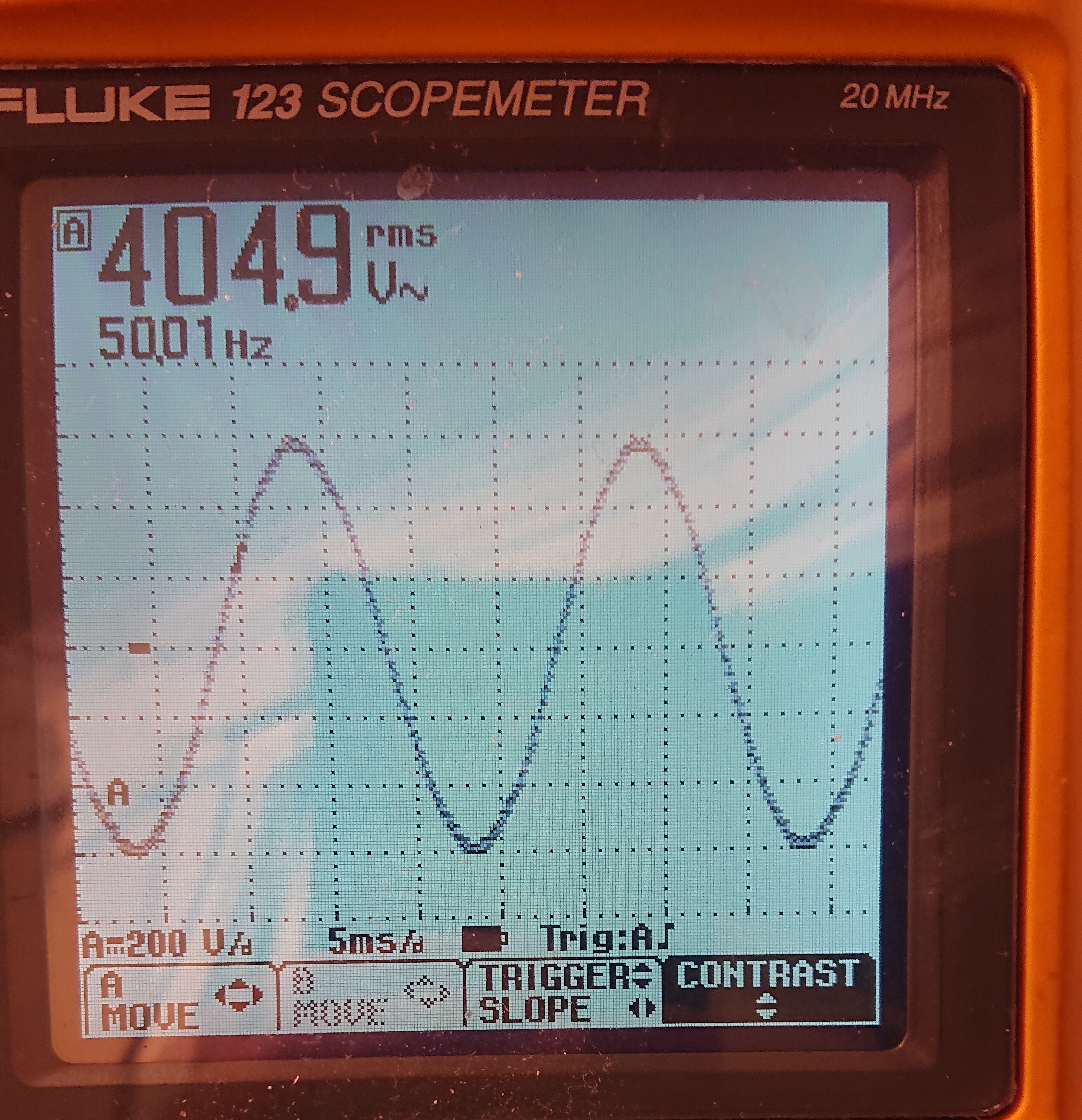
This is my at-home mains, L1-L2, L1-L3 and L2-L3, respectively. Measurement is taken just after my fuse box, which sits 1 m after the meter board. Feeder to meter board is 3x10mm2 plus PEN, 50 meters, to distribution cabinet, and from there one or more 120mm2 some 150m to the transformer. I believe 10KV on the primary; most HV local nets are that here. All cables are buried.
Nothing was turned off at home, but also I wasn't running anything in my workshop; where I've got several 3-phase induction motors. Time for measurement was 22:20 CEST Friday night, so no industrial loads (this also is a very residential area, and transformer is nearly only feeding homes) and no solar around because darkness..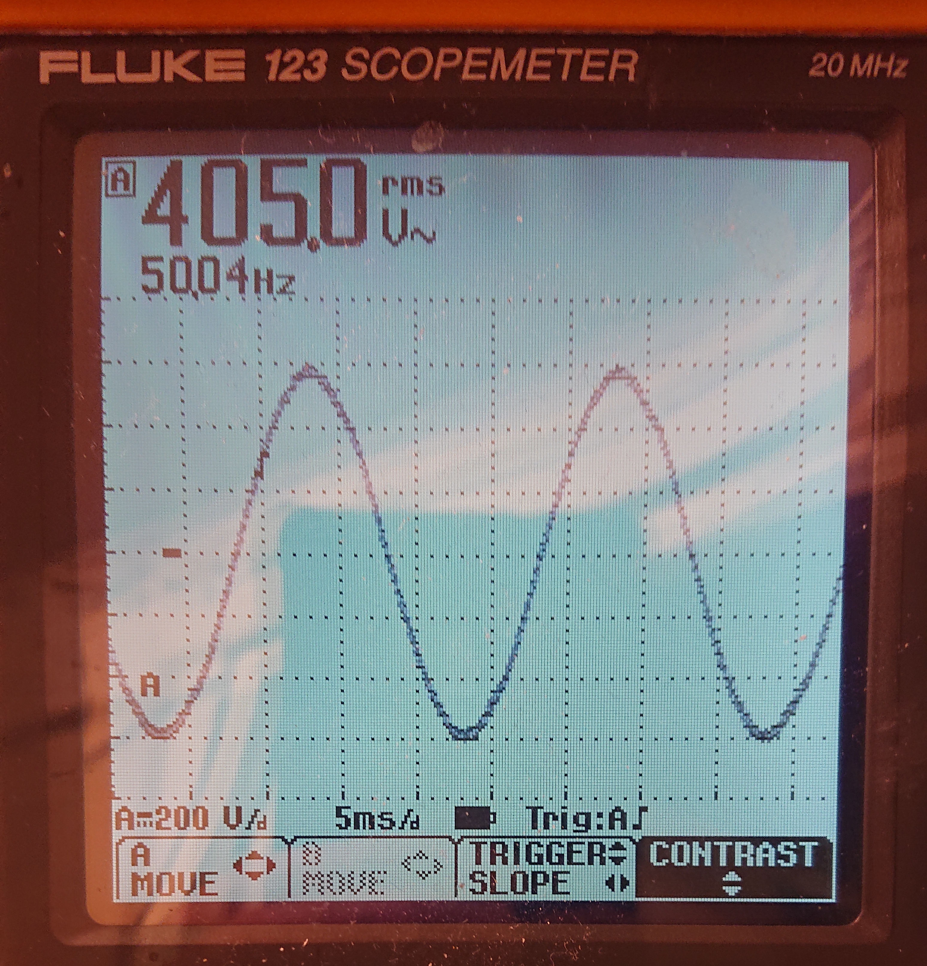

Edit: the direct links are these:
http://vvv.besserwisser.org/Public/Bilder/L1L2.jpeg
http://vvv.besserwisser.org/Public/Bilder/L1L3.jpeg
http://vvv.besserwisser.org/Public/Bilder/L2L3.jpeg -
Same distorted mains waveform at this location (east coast US). I don't remember it looking this bad when I looked years ago...
-
This is my at-home mains, L1-L2, L1-L3 and L2-L3, respectively.
Snip ...
I am so jealous, I wish I had three-phase in my house.
I am also homesick when I see 50Hz.
Regards,
Jay_Diddy_B
-
This is my at-home mains, L1-L2, L1-L3 and L2-L3, respectively.
Snip ...
I am so jealous, I wish I had three-phase in my house.
I am also homesick when I see 50Hz.
Regards,
Jay_Diddy_B
My work here is done!
On a sligthly more serious note, there's no flat roof at all in the waveform. Is it even too peaky? Looking at it, I think it resembles what I get from the low-distortion sine generator in my Tek 500 series audio test setup, (supposedly a nice sine) but i'm in very deep waters w.r.t. judgement here. -
My home lab's mains power supply looks a like this today in leafy Bucks
Using a Micsig DP10013 HVDP and a Pico TA189 current probe 1ma resolution Rigol MSO8000.