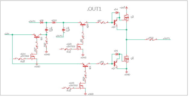
Background: We’re trying to design a PCB with two outputs that can both sink and source current. The sink part is pretty easy, we just use a 2n7002 and a PNP transistor to drive the Gate of an N-channel MOSFET, which then sinks current trough R10 (the shunt). The part just before the Gate with the diode and PNP transistor is found in
here. The High side is a bit more complicated because we wanted to still use an N-channel MOSFET. We take the voltage after the shunt and with a pump charge we put 10V on top of that Voltage, we use this voltage to drive the Gate of the MOSFET so that there is always 10V on the Gate-Source. We haven’t tried any of this out, it should all work fine though, but any tips and tricks for this part of the circuit are welcome. We’d like it to be capable to generate a PWM signal up to 200KHz (at lower currents). With the Covid shortages in mind, we want all this to be built with the most basic and widely available components possible.
The tricky part is measuring the current trough the shunt. The current can go up to 20A and the high rail (it says 24V in the circuit) should be able to handle 60V. We want the circuit to be as versatile as possible. So that’s why the voltage supply could be between 5V and 60V, and the current could be just 50mA but also 20A.
We already tried some options to measure the current. The first and easiest option would be a voltage divider but this has a lot of obvious drawbacks. All other possibilities I found use an op-amp, but we’d like to use a very basic op-amp. So no expensive precision op amp or one that can have a rail to rail of 60V.
For high side shunt measuring I found this circuit on
the Renesas website.
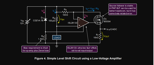
In simulations it works well, but when I build it, the op amp output clips to 0V or just does nothing. Even if this circuit would work it wouldn't suitable for our application, because when we’re driving the load low there will be no voltage across the Zener diode so the op amp won’t have a supply voltage. Also our measuring circuitry should be able to measure currents in both directions which would also require a negative op amp supply. For al these problems we changed the circuit a bit to fit our needs and came up with the following circuit:

The 10V and -10V this circuit uses are made with a charge pump referenced to the output,
so they are DC-isolated from the microcontroller. EDIT: No they are not, as @someone pointed out. I thought it wouldn't work, as there was no real base collector voltage but that seems not to be the case.The idea of the circuit was that the first op amp simply amplifies the shunt voltage to a value between negative 7V and 7V. Then there is a voltage divider which changes the range of the voltage to 1.5V to 8.5V and then the second op amp uses the source follower from the circuit of figure 2 to make a voltage between 0 and 3.3V over a resistor via a current-controlled loop.
This circuit is in my opinion the most promising, I’ve already tried and built a lot of other circuits and to be honest its gotten kind of blurry which circuit had what problem. It would be no problem if there is a solution that uses a totally different approach, but it would be appreciated if it would just consist of passive transistors, MOSFETS and some basic op amps. Although I’m starting to think it is impossible......
I’m not able to take any current measurement in practice with my design. Can someone help me to point out the problems with my approach?
TLDR recap: we want to measure the current in the following circuit and we’d like to use very basic components to do that.

The outputs can sink and source up to 20A, the measurement should be precise enough to measure around 50mA. The voltage source could be up to 60V. Can someone help me to point out the problems with my approach or suggest a totally different approach using simple parts? Because I’m not able to take any current measurement in practice with this design.
/EDIT: Improve readability and change part about charge pump isolation.

 Home
 Help
 Search
 Login
 Register


