I want to build my own
Transistor Tester. However, I would like it to be able to be operated with a standard USB charger.
The problem is that 5.0 USB chargers typically use a switching regulator and the output has several issues, most notably voltage ripple, which makes the measurements inaccurate (according to people related to the Transistor Tester project).
One imperfect solution that was suggested was to at least use a good LC filter; the voltage is then a few 100mV lower, but at least with less ripple.
Another possible solution is to use higher voltages and send them through the linear regulator to get an almost perfect 5V voltage supply. And yes, the new smart fast USB chargers have various protocols that allow a higher voltage output.
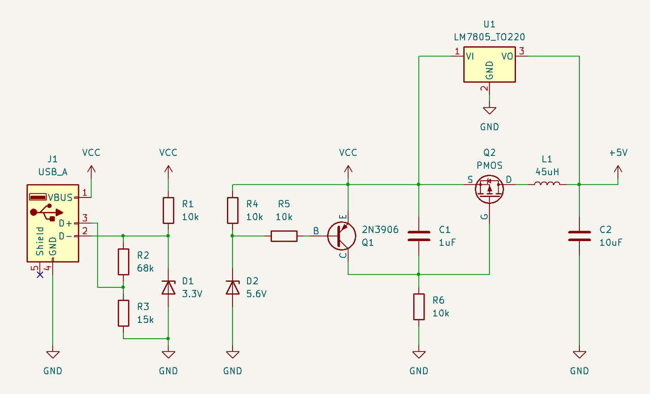
So my idea is to design a circuit that negotiates an input voltage of 9V and passes it on to the linear regulator. However, if only 5V is available, the input voltage is passed to the LC filter.
After reading some information on the internet, especially
this website, I came up with this circuit. The left side negotiates the voltage through the QC protocol, the right side passes the current through Q2 if the VCC is 5V, otherwise the current must flow through the linear regulator. The capacitor C1 should prevent Q2 from opening too quickly and letting 9 V through.
Could you please tell me if this circuit is OK and which common PMOS would you recommend?

 Home
 Help
 Search
 Login
 Register


