OK, I'll settle with LM6171 for now, assuming that CMRR is not (yet) the main contributor to THD. As the LM6171 has a much lower output impedance / higher current drive capability than NE5532, I'm skipping the buffer for now. Thinking about it, I will use an LM6172, so I can swap it for an NE5532 and compare distortion figures directly. If the NE5532 chokes on the capacitive load, I will try buffering it's output with an LM6171.
Upon closer look, I see that the LM6172 CMRR is no worse than NE5532 - typ. 105db / min 70dB vs. typ. 100dB / min 70dB. The most important criteria for my application is that gain should fall off as little as possible 10Hz -> 100kHz; in that department the LM6172 wins. But testing will show
 Linear Technology Application Note 43: Bridge Circuits
, figure 45, seems to be a refinement of the circuit in the Jim Williams book; I'll start there:
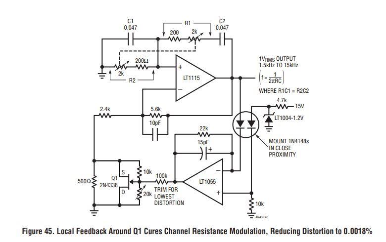
"Figure 46 shows results. Distortion (Trace B) drops to 0.0018% and is composed of 2f, some gain loop rectification artifacts and noise. For reference the circuit’s output (Trace A) and the LT1055 output (Trace C) are shown."
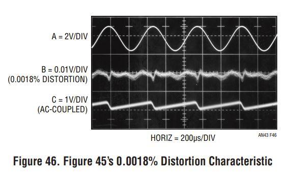
With the S&H peak detector, I will have a ruler-flat trace C, so potentially the THD should be significantly lower.
With respect to JFET selection, I consulted
Fairchild Application Note 6609: Selecting the Best JFET for Your Application:

2N5458 is listed as a prime choice for voltage variable resistor, it's forward transfer admittance is in the same ballpark as 2N4338, it's listed as symmetric (drain and source interchangeable), the range for Vgs(off) is a bit wider but that should be OK. I'll use this one.
With the negative feedback network resistor values as specified in figure 45, gain of 3 (assuming opamp open-loop gain = ∞) will be achieved when the parallel of 560Ω, 20k (assuming the 20k trimmer in middle position) and Rds equals 400Ω. This happens when Rds is ~1.5k, which should be a good operating point for 2N5458.
I would like the oscillator to have an adjustable RMS from 0dB/0.775V (for lowest distortion) to +12dB/3.1V - I will replace the LT1004 reference with a variable reference based on TL431C (or a simple voltage divider potentiometer, assuming the voltage supply is sufficiently accurate and stable)


