-
Today I got my next sick puppy to the bench.
I received this EO174A for a few Euros off the bay.
Current diagnosis: No beam.
It has the option to run off internal or external battery.
So I hooked it up to external 12 V and found that a few basic controls seem to work and I heard a faint whistle from the tube when cycling the power.
First measurements look good.
Next step will be to go through the service manual, test all available voltages and then try to find the fault.
First picture is attached. More to follow as I try to find a fault.
In the meantime:
Is there a try-this-first approach to getting the beam back?
Anode voltage is 1.2 kV, so beyond the capabilities of my multimeters.
-
You are lucky that the service manual (from eserviceinfo.com) also has the CRT datasheet!
If you hear the whistle then the HV generator (or parts of it) probably works.
I would build a HV probe for my DMM. Google "diy hv probe", there are a number of designs out there.
Just check the spec of your DMM, some of them have 1meg input while others have 10meg input resistance!
You could check the heater voltage of the CRT, it is also provided by the HV generator stage.
You could also check the output voltages from the vertical and horizontal amps if they sent the beam off screen.
EDIT:
Here is how you can test that easily with a DMM:
Set the scope into the X-Y mode, but before you do that turn down the beam intensity (just in case the beam reappears).
Measure the voltage at the outputs of the X- and Y-amplifiers. With the corresponding position controls you should be able to balance them, i.e. both side of the differential outputs should have the same potential. With the +85V supply that should be between +40V to +45V. Do this both at the X and Y amplifiers.
If the CRT is working, and only the beam is off the screen, you can see some faint trace (part of a halo) on the screen when you power off the scope and the voltages collapse. Check it in a darkened room.
In that case probably one of the amplifiers is faulty.
Another scope would be helpful for the debugging.
Sounds like a fun project!
Good luck, Peter
-
Thanks for the input, Peter!
Judging from my searches, the EO174A has a known history of cracked solder joints and unplugged cables.
That's where I'll start.
Next step will be the other voltages (which appear to be present)
Scope is required for trouble shooting. One of the sections produces a square wave that has to be adjusted during service.
But I have my Tek 314 next to it. Wonky BNC, but fully functional and adjusted.
So I should be fine here
As for the anode voltage, it's pretty unlucky: Its expected value is 1.2 kV; my tabletop multimeter (the RFT G-1001.500) is rated up to 1.1 kV.
Not sure if I'm willing to risk that.
I'm already considering my options on the HV measurement.
Not really sure, if I want to try it the DIY way, although it's "only" 1.2 kV.
I'll check the LV stuff first. If that doesn't work, I can still get a regular HV probe for my DMM.
(like this one: https://www.reichelt.de/Tastkoepfe-und-Zubehoer/TESTEC-HVP-40/3/index.html?ACTION=3&GROUPID=4043&ARTICLE=32426)
That's 90 EUR well spent, I think. -
I do not think you need to go that fancy with the HV-probe!
For 1.2kV just another 10 MOhm (or 1M) resistor would do fine too!
Use a big (physical size) resistor, those have higher voltage ratings.
If you only have a small resistor, do check its voltage rating.
You can jury-rig it to the end of your DMM probe.
You could use a lesser value resistor too, you just need to extend the input range from 1.1kV to just a bit higher, there is no need to double the voltage range.
In that case the voltage on the external resistor would be smaller too, no need to worry about the voltage rating.
Peter -
A little progress on my side.
I started testing the voltages, while still powering it from 12 V from my bench power supply.
Normal current consumption is about 500 mA.
As I'm powering it from 12 V DC, I currently neglected the 230 V power supply, which is Assembly I in the unit.
Funny thing: While the scope was powered on, something clicked inside and the current jumped to 1.1 A.
At the same time, the green power indicator (battery operation) on the front panel switched off because of the current limit of the PSU. (That's normal behaviour in order to indicate low battery.)
Not sure what that was. Didn't occur again during the test.
Also, the whining noise of the transverter came up now and then.
Now for the voltage:
Currently it seems the transverter is not working. All its voltages are far below spec and the calibration signal (20 mVpp square wave) is missing.
My measurements: (measured // expected)
A 4.2 V // 12 V
B -3.2 V // -10 V
C 28 V // 85 V
D -134 V // -350 V
E -164 V // -450 V
F 0.2 V // 20 V
E-F -170 V // -470 V
I-H 0.0 V // 6.3 V (I suppose that's the heater voltage for the tube)
G -9.9 V / -10.0 V (the only one present)
K-L 0 // 20 mV square wave
I suppose the transverter assembly is the one to start with.
As for the two capacitors on top of the transverter unit:
The larger Tesla unit is an electrolytic cap with 100 uF and I think it's C210.
This one measures okay.
The other one is a 10 nF, and it should be C202m related to the screen lighting circuit.
This one appears to be open. Will have to desolder that one to be sure.
Edit:
While reading the troubleshooting section in the service manual, I suspect that the electrolytic caps in the transverter section are gone, plus some of the rectifier diodes.
So I'm going to have to remove that section and start swapping components...
-
And a few more pics.
Edit: I tried the 230 V supply in the meantime.
Apparently that works.
Its secondary voltages are measured // expected:
7.4 V AC // 6.7 V AC
21.8 V DC // 18 V DC
The 10% over-voltage in the AC section is plausible given that the PS was designed for 220 V AC, and today we have 240 V AC.
I might consider to use the scope with 12 V DC supply once it's working
-
I finally decided to approach the transverter unit.
First thing that has to go: The power supply.
I took a glance at its insides, and I quite like what I see.
An interesting detail:
This scope has no direct power switch for 230 V mains. Instead, the power supply has switches on top (the small balls sticking out), that are mechanically actuated by a rod and the grey plastic switch piece from the front.
Never seen a solution like this before...
btw: Power supply is fine.
DC output is 18 V spot on (while disconnected from the scope)
AC output is still 7,4 V AC.
-
So, I found out a few things.
But first: There is this red square device on top of the transverter unit.
What is that?
Removing the transverter box wasn't that easy. I had to desolder all the wires, and currently I'm not totally confident I'll get it back in in the right order.
But my pics should help with that once I have repaired the thing.
What I've found:
The anode voltage (1.2 kV) is generated with a Greinacher cascade with electrolytic capacitors and E700 diodes. (Visible on the board that's flipped up from the box.)
The diodes do not respond to the diode test of my multimeter. So I have no idea how to confirm their status or what components to replace them with.
The -350V are supplied in a similar fashion.
Same problem with the E400 diode.
The rectifiers for 12V and -10V are fine. So I think the caps might be a problem.
Maybe also the pass transistor for 12 V is gone. Have to find out if I can measure it properly.
Edit: I'd prefer to close this box for good after the repair. So I'm considering changing all the caps and all the E400/E600/E700 diodes to be sure.
I guess after that it should work again and just need some reflow action and adjustments.
Not sure about the rectifiers, as they measure fine (0.6-0.7 V forward bias, OL reverse bias)
Edit 2: Where does the oscillation take place?
Between T201/T202 feeding the primary of the transformer?
The service manual identifies C212 as the culprit if the circuit does not oscillate.
-
Hi Thilo,
That is a really nice and sturdily built scope, and it is also a bonus that you can power it from a battery!
That red square device is a ceramic disk capacitor, 33nF, low voltage, used for bypass purposes (not tight tolerance).
BTW, that 50k trimpot, at this age, is probably not a high reliability component any longer, I would replace that too!
Those old electrolytic capacitors you mentioned, check them for ESR as well, not just for capacitance!
If you get some voltages out from the inverter, then it must be going, probably something is loading it down.
Disconnect those E-series rectifiers, those could very well be the components loading down the inverter.
Instead of looking at that 20mV calibrating signal, look at the signal at the collector of T201, T202. That would tell you how is the inverter running.
You could probably test the unit out of the scope, just provide 10V to the "G" and "M" (24, 23) points.
You need to provide another reference point, "B" (29). The schematics mentions that it is at -10V potential, not ground, though it does not show how does that get there?
The high voltage rectifier diodes (E700 type) you can replace with any 1.5kV diode (or possibly 2kV, in case the inverter is running without any load, then the voltages could be higher).
Just plug in the parameter into the selection guide of your favorite electronic supplier over there. I do not think that speed would be an issue at 15kHz.
For the other diodes (E400, E600 type) simple 1N4007 should do.
You also might want to check for leakage of those 10nF filter capacitors in the HV voltage doubler. Again, there you would need capacitors with about 1.5kV or higher rating.
On second take, having looked at the picture of the circuit board, those are styroflex capacitors, those are most probably fine, the paper tube components are the "HV diodes".
Those E-series HV diodes seem to be stacked rectifier components in those paper tubes, not a single rectifier element, like a diode, with a single junction.
To check it out you would need higher voltage, a DMM diode checker does not provide much more testing voltage than that is enough for a single junction.
Those are also probably not silicon diode junctions either, but possibly selenium. Again, those need higher voltages to check.
Looks like the part number (E400, E600, E700) could mean the number of elements in the unit (4, 6, 7, the length of the units are different).
Use at least 100V to check them. Do check the leakage current, that is what could be loading down the inverter.
Regards, Peter -
This thread might be better suited and addressed in the repair thread. I would ask the moderators to move it.
-
Hi Peter,
thanks a lot for the input!
That is a really nice and sturdily built scope, and it is also a bonus that you can power it from a battery!
Yes, it is indeed. Built like a Russian tank
That red square device is a ceramic disk capacitor, 33nF, low voltage, used for bypass purposes (not tight tolerance).
Yes, I found that on the schematic. Now it's obvious.
BTW, that 50k trimpot, at this age, is probably not a high reliability component any longer, I would replace that too!
The trimpot is less of a concern now, but thanks for the advice.If you get some voltages out from the inverter, then it must be going, probably something is loading it down.
The E700 are part of a Greinacher cascade, producing the 1.2 kV for the anode voltage. So they will see quite substantial voltage.
Disconnect those E-series rectifiers, those could very well be the components loading the inverter.
I will see to get replacements from my supplier next week....
I'm not sure, where B connects to. I'll have to find that wire and its target...
You could probably test the unit out of the scope, just provide 10V to the "G" and "M" (24, 23) points.
You need to provide another reference point, "B" (29). The schematics mentions that it is at -10V potential, not ground, though it does not show how does that get there?
......
1N4007 I have quite a few. So I could replace them directly.
For the other diodes (E400, E600 type) simple 1N4007 should do.
But I still have to check the caps....
That's interesting information.
Those are also probably not silicon diode junctions either, but possibly selenium. Again, those need higher voltages to check.
Looks like the part number (E400, E600, E700) could mean the number of elements in the unit (4, 6, 7, the length of the units are different).
Use at least 100V to check them. Do check the leakage current, that is what could load down the inverter.
Regards, Peter
So I won't be able to test them directly.
What I could do: Replace the electrolytics, replace the diodes (at least E400 and E600), and maybe replace the smaller transistors (will have to take them out of circuit for testing; I'm waiting for my component tester and that might be a useful test run for it).
Then I could put it back, without connecting the units it supplies.
If the voltages are good then, I have further problems down the road.
Regards, Thilo -
This thread might be better suited and addressed in the repair thread. I would ask the moderators to move it.
That's a good point.
Thanks for the hint!
-
Okay, I have taken a closer look at the boards and the caps.
I might have found something, that could have caused the transverter to fail.
There is a lifted eye on the larger board, that receives one pin of the negative side of C212.
With this, the connection between C212 and the transformer is broken.
I'm not totally sure, that this didn't happen when desoldering the cap.
But I'll have to repair this.
I'll wait with repair until I have a replacement cap, as this one measures fine (1.4 mF and 1 Ohm ESR), but most probably has spilt his guts on the board.
Getting closer to the failure
With the cap replaced I'll install a lead from the common collectors to the outside, so that I can measure what's going on inside.
Might be interesting.
-
After further poking around, I found that there has been a major change in the transverter unit for later revisions.
The original design based on KT805AM NPN transistors for oscillation.
But when poking around, the connections didn't make sense. The emitter connections were supposed to be connected to the negative side of C212 etc.
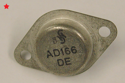
So I took the transistors out and found GD240C, which are germanium PNP transistors.
Of course, the swap doesn't make sense if the rest of the schematic wasn't changed.
So: New schematics.
Found those in a Polish forum.
Now it kind of makes sense.
btw: The two GD240C seem to be gone.
E-B and C-B measure as Diodes with 0.12 V forward bias. Reverse bias they are blocking.
But E-C measures as 0.9 V forward and blocking reverse in one; the other is 0.08 V forward and blocking in reverse.
Seems I have to replace them, unless I got the quick test totally wrong.
-
any AD Transistor may do the job also
greetings
Martin -
any AD Transistor may do the job also
AD meaning "any Germanium PNP"?
greetings
Martin
I wonder if it would be possible to replace them with modern silicon PNPs... -
Another thing I stumbled upon:
According to the data sheet, the CRT has a heating circuit with a rated power of P=0.57 W.
The heater voltage is between points I and H on the transverter, expected value of U=6.3 V.
With these numbers I should find
R=U^2/P=69 Ohm.
Taking the heater current from another data sheet, where it is given with I=0.34 A, I find
R=U/I=18.5 Ohms
If I measure the DC resistance of the heater, I find R=9.5 Ohm, which I find kind of dubious.
Is the CRT's heater broken? Or am I mistaken here?
@PA0PBZ, Martin.M:
I think I have found suitable replacements and will try to order them.
From the values, AD 157 or AD 162 should be suitable. I'll give them a try. -
Cold resistance of the heater will be much lower than hot value. The 9R5 is around right for a cold CRT.
-
Hi Thilo,
Interesting find those Ge PNP transistors!
Do you have a link to the schematics on that Polish site?
You can actually replace those Ge power transistors with Si ones, the inverter would work just fine.
Ge power transistors are getting expensive.
Only thing is that the form factor would be different.
On the "new" schematics they show R206, 150 Ohm, with an asterisk, meaning that its value is selected individually, at build time. I would expect that with Si transistors you might need to increase that value.
On the "original" schematics, with the Si transistors, they only use the "top" resistors, R206, you could just change the circuit to that.
Another point of questionable engineering is the pass transistors in the -10V stabilized power supply, T1, T2. Those are again two Ge transistors in parallel with no emitter resistors. When you do parallel transistors you are supposed to use small emitter degeneration transistors to split the load evenly.
The two transistors would have different Vbe values, and consequently the current through them would not be the same.
As another point, I would simply replace those two Ge transistors with one Si power transistor with the appropriate rating, the higher Vbe value of the Si device would not make any difference.
Again, mounting would be different.
Regards, Peter
-
...
You could probably test the unit out of the scope, just provide 10V to the "G" and "M" (24, 23) points.
You need to provide another reference point, "B" (29). The schematics mentions that it is at -10V potential, not ground, though it does not show how does that get there?
...
It's getting quite complicated with these old units.
But I managed to find out about these voltages.
The -10V fed into the transverter on connection G (via the fuse) is a primary supply voltage coming from the regulator board and includes potential battery supply.
The -10V on point B is a secondary supply produced by the transverter and daisy-chained to all other boards for reference and supply.
M is the ground reference, produced in the power supply unit.
In other words: G and M form the actual power supply of -10 V DC;
B is a -10V supply fed to the other units. -
Hi Thilo,
Found them here:
Interesting find those Ge PNP transistors!
Do you have a link to the schematics on that Polish site?
http://www.elektroda.pl/rtvforum/topic1549482.html
(I used Google translate to figure it out )
They changed the design quite considerably, including replacing a whole bunch of Ge trannys with Si ones.You can actually replace those Ge power transistors with Si ones, the inverter would work just fine.
I thought about that. Maybe BD180 might be a solution.
...
On the "new" schematics they show R206, 150 Ohm, with an asterisk, meaning that its value is selected individually, at build time. I would expect that with Si transistors you might need to increase that value.
In another forum I found the suggestion to use BD136 or BD138, including adjustment of base resistor R206.
I should try that, I think.
edit: The only problem is, that the original GD240C form a matched pair. It might be hard to reproduce that. (at least with as little experience as I have)
Another point of questionable engineering is the pass transistors in the -10V stabilized power supply, T1, T2.
Questionable? Maybe.
...
I'll see as soon as I have the transverter working.
The -10V supply seems to work fine so far.
Regards,
Thilo -
Hi Thilo
If you are going to replace the transverter transistors change R206 for a 500 ohm or 1k ohm pot, adjust bias forfastbest rise and fall time on the collector voltages and also monitor the -10V current. -
Gonna try that.
I just ordered a batch of BD138 (enough to maybe even find a matching pair) and will see to put them into the transverter.
Also, I'll see to put a pot in place of R206, outside the can, so that I can adjust in-circuit.
And I will add measuring points for the collector voltages to monitor them from outside.
Looking forward to the outcome.
I could mark off the following points so far:- 230V power supply semms to work
- CRT seems to be okay. We will see, once the transverter is working.
- Transverter: Oscillation doesn't work due to faulty Ge PNPs. Should be able to replace them with similar Si PNPs
If that works, all voltages should be back.
If my components are here next week, I'll replace them and give it a test drive.
You guys are great!
-
...
I checked with repair entries in a German forum. Apparently, transistors T1, T2, and T3 are pretty robust.
Another point of questionable engineering is the pass transistors in the -10V stabilized power supply, T1, T2. Those are again two Ge transistors in parallel with no emitter resistors. When you do parallel transistors you are supposed to use small emitter degeneration transistors to split the load evenly.
The two transistors would have different Vbe values, and consequently the current through them would not be the same.
As another point, I would simply replace those two Ge transistors with one Si power transistor with the appropriate rating, the higher Vbe value of the Si device would not make any difference.
Again, mounting would be different.
Regards, Peter
They said it's easy to replace them with Si transistors without problems.
To be honest, I'd rather not try to improve the overall design. If it works, it works, and, with my little experience, I'll leave them alone unless they fail.
I'll consider your input for my learning, though, and for future troubleshooting in this very scope. My feeling is that the transverter is not the only problem.
Thanks for your valuable input!
Thilo
Edit: In the meantime I ordered both the BD138 and the GD240 replacement.
Hope they arrive this week, so that I can move to the next step this weekend.