-
Repairing a GW Instek Triple Channel Power Supply that Struggles to Turn On
Posted by The_PCB_Guy on 12 Aug, 2018 22:31 -
Today I bought a GW Instek triple channel power supply for a really good price. The seller knew what it was but clearly hadn't tested it. When I tried to power it on the LED screens flickered a little bit, I saw numbers try to pop up, and the lights on the front panel also flickered a few times. After a second or two everything just shut off and stayed off, regardless of how many times I tried cycling power. I checked all the fuses (the one that's part of the IEC socket as well as all of the ones inside the unit) and all measured good. What's interesting is after the unit was off for a quite a wile, as I was checking the fuses, when I tried again to power it up the LEDs flickered like they did originally (though for not quite as long as before), but the end result is the same - everything shuts off (the fan tries to spin a tiny bit but doesn't even make it past its starting position - I just see it "wiggle" a bit).
I'm not quite sure where to begin with this one. I don't know if there is some sort of protection that could be kicking in, though what would cause this sort of behavior on power-up without blowing fuses? There's not enough time for temperature to be an issue either, so a thermal cutoff seems unlikely as well.
Thoughts and suggestions are appreciated. If there is any other information I can provide that might help, please let me know.
Thank you,
Matt -
Pretty stupid to expect a decent answer without telling what model it is. It could be just anything - linear or SMPS, MCU controlled or analog. At least check power rails at display part.
-
Pretty stupid to expect a decent answer without telling what model it is.
DOH! That was embarrassing. I was going to put in the model number and apparently blanked. My apologies for the oversight.
Anyway, it's a GW Instek GPS-3303: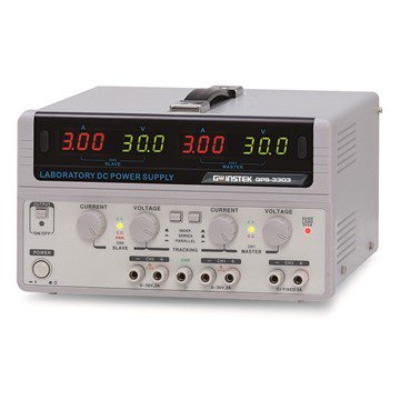
I don't think it's just a display issue because none of the unit seems to turn on. I suppose it could be a back-end issue, perhaps a bad MOV on the supply input? It actually acts like the entire unit isn't getting any power at all (after the initial flicker, if there is one). -
Ok, so I've spent all evening troubleshooting this. I'm getting power at the main switch and the switch is doing what it should. After the main power switch the mains supply goes to the AC selector switches at the back of the unit, selecting between 100V, 120V, 220V, and 240V. The transformer does not hum and I get nothing on the 12VAC output to the control board (except occasionally on first power-up when everything flickers). So in my mind that seems to narrow it down to either the AC selector switches or the primary of the transformer. I decided to measure the DC resistance across the mains cord with the power switch on, and the AC selector switches in each of their configurations. I measured a constant 640 kohms, regardless of the setting. This seems to suggest that either the neutral connection on the AC selector switch board is broken, or the neutral connection within the transformer is broken. I have yet to determine which. Tomorrow I will pull out the selector switch board and check that. Upon inspection the solder joints appear solid, but I can't guarantee that yet. Tomorrow I will know for sure. I'm hoping the problem isn't within the main transformer, as I assume that would be BER.
This, of course, is assuming I traced the circuit correctly and the mains goes directly from the plug to the main power switch, to the AC selector switches, to the primary (or primaries) of the toroidal transformer.
This would be made so much easier if I had the schematic for the GPS-3303 but I have been unable to find one, and I notice there are others here at the EEVblog forum who also haven't been able to find one.
Regards,
Matt -
A service manual of the supply should help. From the looks of the schematic of the power supply/transformer area, there are at least 7 fuses that you could check as well as a number of voltages and filter caps. Because there appear to be multiple symptoms this is where I'd start looking.
https://elektrotanya.com/gw_instek_gpd-2303s_3303s_4303s_sm.pdf/download.html -
I'd use a DMM with a continuity function to trace from one prong on the power plug through the primary circuit to the other prong. Since the unit isn't plugged in to mains while you're doing this, you can poke, pry, and shake things as necessary to find the bad connection without worrying about sparks and smoke.
Ed
-
A service manual of the supply should help. From the looks of the schematic of the power supply/transformer area, there are at least 7 fuses that you could check as well as a number of voltages and filter caps. Because there appear to be multiple symptoms this is where I'd start looking.
I came across that service manual already but unfortunately the 3303 and the 3303S are completely different animals. That being said, I will still be looking through the 3303S manual in case the input circuitry is similar. I have already checked all of the visible fuses (the one built into the IEC mains connector, as well as 5-6 on the board inside the unit) and all measure fine. It could be a cap, though the caps would be on the output (rectified) side of the transformer. I'm not getting anything on the secondaries though (disconnected from the board) so that leads me to think it might be on the primary side.
https://elektrotanya.com/gw_instek_gpd-2303s_3303s_4303s_sm.pdf/download.html
Thanks for the suggestion and the link.
Matt -
I'd use a DMM with a continuity function to trace from one prong on the power plug through the primary circuit to the other prong. Since the unit isn't plugged in to mains while you're doing this, you can poke, pry, and shake things as necessary to find the bad connection without worrying about sparks and smoke.
Thanks for the suggestion. I actually already tried this and as I mentioned in one of my earlier posts I measured a constant 640 kohms from one prong to the other when the main power switch was closed, for all of the different AC voltage settings. This resistance seemed a bit high for the primary of such a large transformer, so I would guess it might be the AC selector switches (seems unlikely) or the neutral line is flaky (on the selector board or, Heaven forbid, within the transformer itself).
Ed
I'll be looking more into this after work tomorrow.
Cheers,
Matt
No, you measured resistance. I'm talking about continuity. You know - the little beeping thing. You could use resistance, but this is what the continuity function is for.
Go step by step from one prong around to the other and find where the beeping stops. The list will be something like power cord, power switch, fuse, voltage selector, transformer, maybe the power switch again, and finally power cord again. If there isn't an exposed spot to probe, use a tiny pin to puncture the wire insulation. Your path will test each item one after another. If you don't get a beep, the previous item is the defective one.
Ed
-
Posting clear, in focus, high resolution pictures will help if we can't find a service manual.
-
No, you measured resistance. I'm talking about continuity. You know - the little beeping thing.
I am familiar with continuity testers. The problem is that, unfortunately, the continuity test function on my multimeter is based on resistance. Some meters may supply a higher voltage in continuity mode but if I remember correctly mine does not - it is very cheap. With my meter I get more information by measuring resistance than I do from the continuity test. I could probably hook up a 9-12V battery and a meter or something and test continuity that way. You could use resistance, but this is what the continuity function is for.
Go step by step from one prong around to the other and find where the beeping stops. The list will be something like power cord, power switch, fuse, voltage selector, transformer, maybe the power switch again, and finally power cord again. If there isn't an exposed spot to probe, use a tiny pin to puncture the wire insulation. Your path will test each item one after another. If you don't get a beep, the previous item is the defective one.
EdPosting clear, in focus, high resolution pictures will help if we can't find a service manual.
I will see what I can do when I get home from work
-
No, you measured resistance. I'm talking about continuity. You know - the little beeping thing.
I am familiar with continuity testers. The problem is that, unfortunately, the continuity test function on my multimeter is based on resistance. Some meters may supply a higher voltage in continuity mode but if I remember correctly mine does not - it is very cheap. With my meter I get more information by measuring resistance than I do from the continuity test. I could probably hook up a 9-12V battery and a meter or something and test continuity that way. You could use resistance, but this is what the continuity function is for.
Go step by step from one prong around to the other and find where the beeping stops. The list will be something like power cord, power switch, fuse, voltage selector, transformer, maybe the power switch again, and finally power cord again. If there isn't an exposed spot to probe, use a tiny pin to puncture the wire insulation. Your path will test each item one after another. If you don't get a beep, the previous item is the defective one.
Ed
More info isn't necessarily good info. Everything on the primary side of a linear power supply is very low resistance. I just measured the resistance between the prongs of a 50V, 5A linear variable lab supply. I measured about 3 ohms - including the lead resistance. Trying to measure resistance in that situation is a waste of time. You've got a bad connection somewhere. The continuity test is the first test to try in a situation like this. You don't need a higher voltage.
Ed
-
Quote
More info isn't necessarily good info. Everything on the primary side of a linear power supply is very low resistance. I just measured the resistance between the prongs of a 50V, 5A linear variable lab supply. I measured about 3 ohms - including the lead resistance. Trying to measure resistance in that situation is a waste of time. You've got a bad connection somewhere. The continuity test is the first test to try in a situation like this. You don't need a higher voltage.
Ed
I understand, but a resistance measurement tells me exactly the same thing as a continuity measurement, but it also tells me how off the resistance is from what I would expect. For example this 640k measurement tells me there's not a complete break, just a high-resistance connection somewhere or perhaps a flaky joint. This is far more useful to me than just seeing "is it connected or not" using the continuity measurement. Maybe it's just personal preference but unless I'm beeping out known near-zero resistances (sub-ohms, like when I'm trying to reverse-engineer a board and just need to know what joint is connected to what joint), I usually stick to a general resistance measurement. Not trying to be argumentative, I do appreciate your input, I'm just stating my own preferences.
Anyway, there's definitely a flaky connection somewhere and I will be trying to track that down this evening after I get home from work.
Thanks again,
Matt -
Ok, I am VERY annoyed. I just typed up a response with a few photos, comments, test results, etc. but after hitting "Post" it just deleted everything! DAAAAVE!!!!
What I was trying to say was that I'm not much of a photographer, and all I've got is the camera from my Galaxy S5, but here's what I can do. If anyone has any requests for photos of specific parts of the power supply, let me know. I also attached the MattCAD (DaveCAD ripoff) reverse-engineered schematic of the AC selector, in case it's useful. It seems to be working just fine though, so I don't think that's the problem.
One or two of the photos show the main power switch plug being disconnected. I did that while probing around, so don't worry - it wasn't like that when I was trying to test the unit
It occurred to me that I was measuring the resistance of the primary side of a step-down transformer, so the resistance will be rather high. Ed, I'm not sure how you measured only 3 ohms on the primary. That seems absurdly low...? That being said, there is continuity between all of the primary taps, there just seems to be a high resistance (higher than expected - ranging between 600K and 1M) between the hot "leg" of the transformer and the taps. Perhaps this is normal but it still strikes me as a little high. I'm a bit concerned that it may point to a damaged primary winding which I assume would be BER.
Also, for the record, some of you seem to be talking down to me like I'm a complete newbie. I wanted to make it clear that I am an Electrical Engineer by profession and understand the basic concepts behind the design of power supplies. You can speak in technical terms and I will understand, you don't have to dumb it down for my sake. This is just the first power supply I have ever tried repairing, so it's a learning experience for me.
Thanks,
Matt
-
It occurred to me that I was measuring the resistance of the primary side of a step-down transformer, so the resistance will be rather high.
You're making DC measurements on the primary of a transformer. It doesn't matter what the secondary is.Quote
Ed, I'm not sure how you measured only 3 ohms on the primary. That seems absurdly low...?
No, it isn't. I wandered around and made some measurements of the primary circuits of a few devices as follows:
HP 6622A Linear Power Supply (160W output) - 0R9
HP 6002A Linear Power Supply (200W output) - 0R8
Goldstar GP-505 Linear Power Supply (250W output) - 1R0 -- This is the unit I originally measured. Looks like the switch was a bit dirty when I made my initial measurements.
Then I measured a mil spec. hermetically sealed 360W isolation transformer. 110V in, 110V out. Nothing else. It measured 1R6. Note that unlike my initial measurement, these measurements do NOT include lead resistance.
Are you beginning to see the pattern, Matt? Your power supply has a total output of 195 watts so you should be seeing similar numbers.QuoteThat being said, there is continuity between all of the primary taps, there just seems to be a high resistance (higher than expected - ranging between 600K and 1M) between the hot "leg" of the transformer and the taps. Perhaps this is normal but it still strikes me as a little high. I'm a bit concerned that it may point to a damaged primary winding which I assume would be BER.
These devices that have 110/220 switches typically have two primary windings. They run in series for 220V or in parallel for 110V. Since the 3303 has 100/120/220/230 volt settings, you should have a total of 6 wires coming from the transformer to the voltage selector. That's consistent with your drawing showing J102 and J103. But the gray wire doesn't seem right. Can you recheck that? With J102 and J103 unplugged, is there continuity on the transformer side of J102 and J103 between them or is the continuity only within each connector?
Don't forget that you've never seen this thing working. Maybe someone else got to it before you and messed up the wiring.QuoteAlso, for the record, some of you seem to be talking down to me like I'm a complete newbie. I wanted to make it clear that I am an Electrical Engineer by profession and understand the basic concepts behind the design of power supplies. You can speak in technical terms and I will understand, you don't have to dumb it down for my sake. This is just the first power supply I have ever tried repairing, so it's a learning experience for me.
Oh, an Electrical Engineer. Okay, I'll take it easy on you. After all, we Engineers have to stick together!
Seriously, on a forum like this, there's no way to tell if you're talking to a kid in high school or a grey beard who's forgotten more than most of us will ever know. I really do have a grey beard, but I haven't forgotten everything ...... yet ..... I don't think.
Ed
-
This unit looks quite similar but not exactly the same?
Might be worth hunting down and comparing. This is quite similar to the GPC-3020 which I have, thats why I have it. Its too big to upload. I think I was pointed to it here so a search here might find its source.
Tek_PS280-283_Service_Manual_Schematics.pdf
EDIT: Actually, digging down a little bit, this one in the manual appears to be a completely different unit, it has a regular type transformer and yours has a toroid, also it has a passive heatsink and yours (like mine) has a fan and forced air cooling through an internal heat sink. (making it insanely noisy when working) -
You're making DC measurements on the primary of a transformer. It doesn't matter what the secondary is.
What I meant was that there are going to be more windings on the primary so resistance will be higher, but again, not THAT much higher.Quote
No, it isn't. I wandered around and made some measurements of the primary circuits of a few devices as follows:
HP 6622A Linear Power Supply (160W output) - 0R9
HP 6002A Linear Power Supply (200W output) - 0R8
Goldstar GP-505 Linear Power Supply (250W output) - 1R0 -- This is the unit I originally measured. Looks like the switch was a bit dirty when I made my initial measurements.
Then I measured a mil spec. hermetically sealed 360W isolation transformer. 110V in, 110V out. Nothing else. It measured 1R6. Note that unlike my initial measurement, these measurements do NOT include lead resistance.
Are you beginning to see the pattern, Matt? Your power supply has a total output of 195 watts so you should be seeing similar numbers.
Yep, I believe you. I just measured across the prongs of a BK Precision power supply and measured 1.6 ohms, so that along with all your examples has me convinced.Quote
These devices that have 110/220 switches typically have two primary windings. They run in series for 220V or in parallel for 110V. Since the 3303 has 100/120/220/230 volt settings, you should have a total of 6 wires coming from the transformer to the voltage selector. That's consistent with your drawing showing J102 and J103. But the gray wire doesn't seem right. Can you recheck that? With J102 and J103 unplugged, is there continuity on the transformer side of J102 and J103 between them or is the continuity only within each connector?
Don't forget that you've never seen this thing working. Maybe someone else got to it before you and messed up the wiring.
The gray wire (HOT) goes directly from the main power switch board into the transformer. Then the six taps come out and connect to the AC voltage selector board via J102 and J103, which then connect them - in whatever configuration- to the common neutral wire that goes back to the main power switch board. I didn't draw any of the taps on the primary.
During my probing I had unplugged the taps from the AC selector board and there was continuity between all of the taps. But the connection between the taps and the HOT leg of the transformer was high-resistance.QuoteSeriously, on a forum like this, there's no way to tell if you're talking to a kid in high school or a grey beard who's forgotten more than most of us will ever know. I really do have a grey beard, but I haven't forgotten everything ...... yet ..... I don't think.
I understand, I'm a moderator on one electronics forum and a member on several others so I have had the same issue. I try to help someone only to find out they are completely clueless about everything electronic, so I have to start all over again with the very basics. I should have mentioned my experience level in my initial question.
Thanks,
Matt -
Curiouser and curiouser.....
If there's continuity between J102 and J103, your AC selector drawing is wrong because it shows multiple taps being shorted out. There will be smoke! However, if J102 and J103 are two separate, identical coils, then your drawing works as described below.
BLU and RED = 115V
YEL and BRN = 105V
ORG and BLK = 0V
S102/S103 Switch Positions (Left or Right)
LL = BLU/ORG in series with RED/BLK = 230V input
LR = BLU/ORG in parallel with RED/BLK = 115V input
RL = YEL/ORG in series with RED/BLK = 220V input
RR = YEL/ORG in parallel with BRN/BLK = 105V input
Please check your drawing and my tracing to make sure they're correct. While you're at it, is there an unused solder hole on the AC selector board that would connect to the black wire? I have a theory....
Ed -
Curiouser and curiouser.....
If there's continuity between J102 and J103, your AC selector drawing is wrong because it shows multiple taps being shorted out. There will be smoke! However, if J102 and J103 are two separate, identical coils, then your drawing works as described below.
BLU and RED = 115V
YEL and BRN = 105V
ORG and BLK = 0V
S102/S103 Switch Positions (Left or Right)
LL = BLU/ORG in series with RED/BLK = 230V input
LR = BLU/ORG in parallel with RED/BLK = 115V input
RL = YEL/ORG in series with RED/BLK = 220V input
RR = YEL/ORG in parallel with BRN/BLK = 105V input
Please check your drawing and my tracing to make sure they're correct. While you're at it, is there an unused solder hole on the AC selector board that would connect to the black wire? I have a theory....
Ed
Yep, I made a mistake - I was speaking from memory and apparently I remembered incorrectly. The schematic I showed for the AC selector is correct, and there is not continuity between J102 and J103. There is, however, continuity between all 3 pins on each of the individual connectors (i.e. all three pins on J102 are connected together and all three pins on J103 are connected together). This makes sense if there are two independent windings that are switched in series/parallel as you describe.
There are no other solder joints on the AC selector board. The only direct joint is the blue wire from the switched Neutral. The only other connections are brought out through the connectors as shown in the diagram.
Front and back photos of the AC selector switch board are attached.
-
The more tests I perform the more I'm convinced that the primary winding of the main transformer is damaged. I effectively disconnect the transformer from everything else in the power supply and measure resistance/continuity across the primary (common to taps) and consistently measure high-resistance between ~650K-~1M. As far as I know nobody sells a replacement transformer for these units, and even if they did I'm not convinced it would cost substantially less than a new power supply. This may be beyond economical repair.
-
If you get no continuity from the primary-common to the taps, then the primary common is open. You should get continuity between taps, and high Z to the secondary.
The panel meters lit up intermittently, so you should be able to poke and prod to find the location of the break.
If you are sure it's the transformer, take it out and try surgery- unwind the tape and get to the primary-common winding/wire connection. Unless you can find a "dent" in the winding, if the transformer got banged during assembly.
I recall bad power transformers in cheap eBay bench power supplies, they were assembled (wound) wrong and then people sell off the dud PSU's.
Ask GW Instek for cost on a replacement xfmer. -
If you get no continuity from the primary-common to the taps, then the primary common is open. You should get continuity between taps, and high Z to the secondary.
It is high resistance between the primary common and the taps, but low resistance between each of the three wires on each of the connectors. As mentioned before this is consistent with Ed's comment about an isolated primary coil that is switched in series or in parallel with the main primary/taps by the AC selector switches. The damage would most definitely be on the common side, based on my measurements.QuoteThe panel meters lit up intermittently, so you should be able to poke and prod to find the location of the break.
In order to do this I'll have to crack open the transformer itself. I have already poked and prodded the rest of the circuit to narrow it down to the main transformer.QuoteIf you are sure it's the transformer, take it out and try surgery- unwind the tape and get to the primary-common winding/wire connection. Unless you can find a "dent" in the winding, if the transformer got banged during assembly.
This is probably what I will end up doing, though obviously I was saving it as a last resort. I may be at that point though. Since this is becoming more of a passion project now it might just be worth the added effort. If the damage is near enough to the common side (and the common windings are closer to the outside of the transformer) then it may just be repairable, though realistically it would be impractical. Like I said though, now that this is turning into a passion project I might try it anyway.QuoteAsk GW Instek for cost on a replacement xfmer.
Good thought. Wonder if they would offer them to customers, or if they would require the customer just send their unit in for repair? -
The problem with repairing the transformer is that typically, the low voltage secondary windings are on the top and the primary is buried underneath. So you'd have to unwind everything to get to the bad connection on the primary. But you might not have to do that ......
Keep the following things in mind:
- notice the goofy solder connection for the grey wire. It's soldered to a brown wire stub that goes to the power switch board. Looks to me like a last minute design change.
- notice the two blue wires and the other brown wire that are in the same connector as the brown stub.
- the voltage selector wiring is totally ordinary except there's no connection between the black wire and the hot side of the line.
Here's my theory. I think that the brown stub originally went to the voltage selector board and connected to the black wire. The grey wire wasn't used at all. But then they realized that they should have used the grey wire so they made the design change. Why? Maybe the grey wire has a thermal fuse and the black one doesn't but otherwise, grey and black are the same. I realize that right now, there's no place on the voltage selector board to connect the brown wire and I'm really annoyed at that!
So what am I proposing? Matt, are you up for some more testing? Do you have access to a variac? I'd like you to connect the variac between the black or orange wires and the blue or red wires. With the voltage selectors set to 115V that should put the variac output across the two windings in parallel just like they should be. Disconnect the transformer secondaries from the circuit. Monitor the current out of the variac and the voltage across one of the secondaries. Start the variac at 0V and slowly raise it while watching the current. If everything is correct, I would expect to see a current of less than 200 ma. with full line voltage across the coils. The voltage on the secondary can be compared to the capacitor voltage that it connects to.
If this test works, you can just abandon the grey wire and jumper the brown stub over to the black wire on the voltage selector board.
Ed
-
The problem with repairing the transformer is that typically, the low voltage secondary windings are on the top and the primary is buried underneath. So you'd have to unwind everything to get to the bad connection on the primary. But you might not have to do that ......
Keep the following things in mind:
- notice the goofy solder connection for the grey wire. It's soldered to a brown wire stub that goes to the power switch board. Looks to me like a last minute design change.
- notice the two blue wires and the other brown wire that are in the same connector as the brown stub.
- the voltage selector wiring is totally ordinary except there's no connection between the black wire and the hot side of the line.
Here's my theory. I think that the brown stub originally went to the voltage selector board and connected to the black wire. The grey wire wasn't used at all. But then they realized that they should have used the grey wire so they made the design change. Why? Maybe the grey wire has a thermal fuse and the black one doesn't but otherwise, grey and black are the same. I realize that right now, there's no place on the voltage selector board to connect the brown wire and I'm really annoyed at that!
So what am I proposing? Matt, are you up for some more testing? Do you have access to a variac? I'd like you to connect the variac between the black or orange wires and the blue or red wires. With the voltage selectors set to 115V that should put the variac output across the two windings in parallel just like they should be. Disconnect the transformer secondaries from the circuit. Monitor the current out of the variac and the voltage across one of the secondaries. Start the variac at 0V and slowly raise it while watching the current. If everything is correct, I would expect to see a current of less than 200 ma. with full line voltage across the coils. The voltage on the secondary can be compared to the capacitor voltage that it connects to.
If this test works, you can just abandon the grey wire and jumper the brown stub over to the black wire on the voltage selector board.
Ed
This is a fascinating proposition. I did notice the sloppy solder joint between the switched brown wire and the gray primary wire, but had no clue why that was done. At first I thought there might be some sort of thermal fuse under the heatshrink tubing, but when I removed it all I saw was a glob of solder.
I happen to have a Variac (three of them, in fact - one even came with the lot the power supply was included in when I bought it). I'll have to give this a go. Not sure if I'll have time tonight but I should definitely be able to give it a shot tomorrow evening after work.
Thanks again for the continued support.
Regards,
Matt -
Although you say the manual I linked to in post #4 is different than your supply, if you follow the primary switch wiring on page 89 of the one I linked to, you will see that although they are drawn differently the wiring and switches are identical. The drawing you have in post #13 showing the primary wiring/switches has an error. There are 2 separate primary windings of 120 volts each with a tap at 110 volts. For low voltage (110/120) they are switched in parallel and for high voltage (220/240) they are switched in series. I've assumed where it looks like you are in the U.S. that you have the switches set correctly for 120 VAC or parallel primary connection.
If the two primaries are in parallel there is an extremely low chance that both are open and if you follow my marked up drawing of the one you had in post #13 you can see two complete and separate paths for the primary current through the two windings. Unless the supply was wired for 120 and connected to 240 to burn both windings (or a buried thermal fuse for each winding), you have a wiring error somewhere. As others have stated the resistance of the primary windings should be a very few ohms. Checking the resistance on J102/J103 should show low resistance and be identical on both connectors.