Author Topic: Simple VNA  (Read 6633 times)

0 Members and 1 Guest are viewing this topic.

Offline ealexTopic starter

  • Frequent Contributor
  • **
  • Posts: 318
  • Country: ro
Simple VNA
« on: July 04, 2016, 12:56:09 pm »
Hello

I've been playing with RF for some time and i'm starting to feel the need for some basic tools: a way to graph filter, amplifier response, etc.
I have a good signal generator but it's very slow and i can't connect it to a PC.
Checking a few points are ok - dial in frequency, look at VRMS on a scope then convert to dBm.

I've seen some AD8302 ( http://www.analog.com/media/en/technical-documentation/data-sheets/AD8302.pdf ) modules that output gain and phase difference.

I also need an oscillator that can cover ~ 1-100MHz.
The first idea is to use a DDS chip - but they are quite expensive.

After looking around the net ( and at my other signal generator schematics ) I've decided to use the following architecture, with some changes - see the description below.


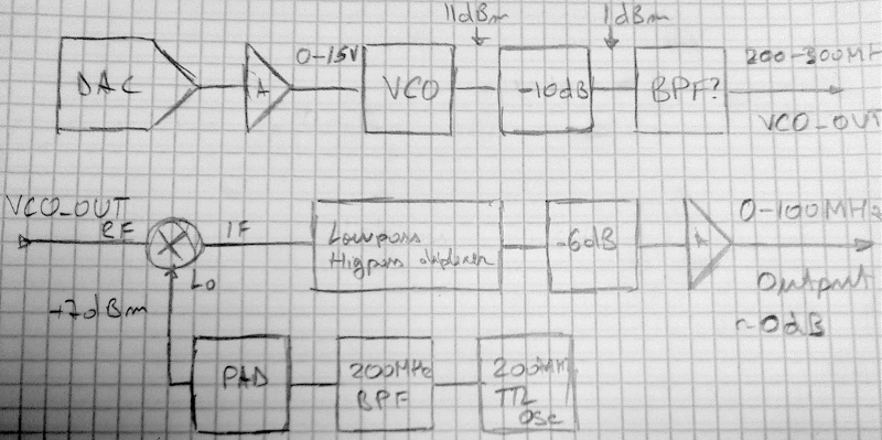
- a very good DAC - 0-15V will cover 195 - 315MHz  -> 16 bits will have 27.5kHz steps, 24 bits will lead to 107Hz steps
- DAC amplifier - extend DAC range to 0-15V
- VCO: V200ML01 200-300MHz, http://pdf.datasheetcatalog.com/datasheet/Zcommunications/mXrwuxs.pdf
 -10dBm pad, as specified in http://www.zcomm.com/wp-content/uploads/2014/06/AN-102.pdf
band pass filter - 200-300MHz ? is it required ?
- should I add an amplifier as well ? I can't test a diy 200-300MHz amplifier, and if I add a MMIC I'll have to reduce the output power again so I do not overload the mixer
- 200MHz TTL oscillator - square wave
- 200MHz low pass or a narrow band pass filter, so I will not mix higher harmonics
- a pad or buffer to get the signal to ~7dBm for the mixer LO drive
- high pass / low-pass diplexer, at 100MHz to properly terminate the mixer
- attenuator and power splitter, to split the signal 2 ways
- 2 amplifiers, one for the normal output and one for the reference output
- a AD8302 module
- a decent ADC - 12 bits should be enough

For the software - something PC based or get a small A20 board and a compatible LCD to make a stand-alone unit.

Is there anything that I forgot ?
 

Offline uncle_bob

  • Supporter
  • ****
  • Posts: 2441
  • Country: us
Re: Simple VNA
« Reply #1 on: July 04, 2016, 05:12:04 pm »
Hi

A basic DDS chip is a sub $30 item as a raw chip and under $50 as a "kit board" from a lot of different places. I believe your synthesizer will ultimately cost more and be much less stable than a DDS. Without a PLL involved, the 100 to 200 MHz VCO is going to be wandering all over the place ....

Bob
 

Offline orin

  • Frequent Contributor
  • **
  • Posts: 445
  • Country: us
Re: Simple VNA
« Reply #2 on: July 04, 2016, 06:59:04 pm »
You might want to look at the following first:

http://sdr-kits.net/VNWA3_Description.html

and/or:

http://n2pk.com

BTW, if you put < 1dBm (after the BPF) into the RF port of a mixer with +7dBm into the LO port, you are going to get < -5dBm out of the IF port - see the datasheets on the Mini-Circuits ASK-1+ or SAM-1+ for example.  It is unclear from the diagram what you expect the IF level to be.


Offline uncle_bob

  • Supporter
  • ****
  • Posts: 2441
  • Country: us
Re: Simple VNA
« Reply #3 on: July 04, 2016, 07:07:54 pm »
Hi

Some basic "let's guess" math:

16 bit DAC into 100 MHz range VCO: 1.5 KHz steps.

Likely stability of a wide range VCO ~ 10 to 100 ppm: 2 to 20 KHz "wander" on the steps over 1 to 100 seconds.

Bob
 

Offline Neganur

  • Supporter
  • ****
  • Posts: 1145
  • Country: fi
Re: Simple VNA
« Reply #4 on: July 04, 2016, 07:21:01 pm »
how about this, done before and proven.

phase detector:
http://www.scottyspectrumanalyzer.us/slim_PDM.html

DDS:
http://www.scottyspectrumanalyzer.us/slim_DDS_107.html

ADC:
http://www.scottyspectrumanalyzer.us/slim_ADC_16.html

Log detector:
http://www.scottyspectrumanalyzer.us/slim_ld_8306.html

And while you're at it, grab a few other ideas from the individual modules and you'll be on your way to not only understand but also use exactly the measurements needed for what you're trying to achieve:

http://www.scottyspectrumanalyzer.us/msaslim.html (for complete reference)


EDIT 08/2024:(updated the urls) the original .com domain is no longer active and moved to .us - the project is still active on https://groups.io/g/spectrumanalyzer
« Last Edit: August 08, 2024, 07:42:26 am by Neganur »
 

Offline ealexTopic starter

  • Frequent Contributor
  • **
  • Posts: 318
  • Country: ro
Re: Simple VNA
« Reply #5 on: July 05, 2016, 07:57:47 am »
Hello

I've looked at all the above VNA's - they are quite nice.
At one moment i was almost ready to start building the N2PK one.

I don't need "lab grade" gear, at least for now - it's just a hobby
Mostly some basic stuff that will help me learning.

Will it work if I make a board with 1 AD9851 ( N2PK ) then split the signal and use 2 amps as buffers -> that will provide a reference and  the signal to the DUT.

I'll keep thinking about it - maybe it will be cheaper to find a way to remote-control the stuff i already use for a signal generator, and make only the detector side

« Last Edit: July 05, 2016, 09:15:03 am by ealex »
 

Offline cncjerry

  • Supporter
  • ****
  • Posts: 1308
Re: Simple VNA
« Reply #6 on: July 07, 2016, 12:05:48 am »
I built one N2PK VNA and it works great.  I started another because I wanted to use another oscillator and am just about done.  If I finish the second one I'll probably sell the first and keep whichever works better.

There are other designs but most use two signal generators because you need signals in quadrature  (90 degrees out of phase).  There are other designs that sense current and voltage and if you don't really need phase they will work.  I can't remember the guys call, something like W5BIG (the BIG is correct) who makes a device called an AIM something or other, I think, that works well for your needs.  I think his uses the PC sound card but now that I think about it, that one required two oscillators again.

The N2PK works well because of the detector scheme as well as the 24bit ADCs.  The Ad9851's should be scrapped for AD9854s because of the phase noise improvement in the oscillator but I doubt the overall phase noise would improve much as mine is below -135db on average already.  The big limitation in the N2PK is the frequency range but it is accurate as hell.


Share me

Digg  Facebook  SlashDot  Delicious  Technorati  Twitter  Google  Yahoo
Smf