Author Topic: Advantest R3477 9kHz to 13GHz spectrum analyzer  (Read 21627 times)

0 Members and 1 Guest are viewing this topic.

Offline nctnicoTopic starter

  • Super Contributor
  • ***
  • Posts: 26906
  • Country: nl
    • NCT Developments
Advantest R3477 9kHz to 13GHz spectrum analyzer
« on: July 12, 2016, 10:36:22 pm »
A short play with my latest toy: an Advantest R3477 9kHz to 13GHz signal analyzer spectrum analyzer which I got from Korea though Ebay for $1400 ex. shipping. All the recent talk about spectrum analysers made me want to upgrade my Advantest R3131 (9kHz to 3GHz with monochrome screen) to something with a color screen and preferably the ability to write screendumps to a USB stick. After some hunting on Ebay I found the R3477 but since it is called a signal analyzer instead of a spectrum analyzer it might fly under the radar of people looking for a spectrum analyzer. It seems several Korean sellers are unloading a whole bunch of these machines so this may be a good opportunity to get a good deal. However it does not (seem to) have typical EMC measurements like quasi peak detection but so far I have not really needed that for EMC pre-compliance testing. BTW I didn't look specifically for a spectrum analyzer from Advantest but it turned out my third spectrum analyzer is from Advantest as well. I also didn't need anything over 3GHz but getting more is never a deal breaker.
Front:

Rear:


This machine is based on a PC (Pentium 3 AFAIK) and it runs Windows XP embedded. It has a 800x600 TFT touch screen. Unfortunately the touch screen in my one is (was?) slightly damaged which made the pointer to stick in one spot. I think it is easy to replace (it is just cheap resistive touch screen) but first I tried to heat it a little with some hot air and that seemed to have done the trick. Deformed plastic usually goes into it's original shape when heated (think about heat shrink tubing) so a dent in the plastic film could just level out enough. Due to the internal PC it does use quite a lot of power so it needs lots of airflow and thus the R3477 produces a significant amount of fan noise.

A disadvantage is that this spectrum analyzer doesn't have internal DC blocking capacitors so for general purpose use I ordered a DC blocker just to be safe.

Time for some play. First a 3GHz carrier with a 5Hz AM modulated signal. For this test I connected the references of the generator and the spectrum analyzer (in to out) otherwise the frequencies would wander way too much.

Oh and let's see how busy the Wifi band is:

Advantest is also very candid about the expected life of various parts in their equipment:

I tried to find some information about the number of hours it has been on and the number of attenuator cycles it has been through but I have not been able to find that yet. There is a service menu and I expect to find the information there but this is protected by a password which -ofcourse- isn't in the manual.

When I have more time I'll open it up and take some pictures from the inside. I most definitely want a working backup image of the hard drive (according to the manual it is a flash drive) in case it fails or gets corrupted.
« Last Edit: July 12, 2016, 10:42:06 pm by nctnico »
There are small lies, big lies and then there is what is on the screen of your oscilloscope.
 
The following users thanked this post: Wuerstchenhund

Offline uncle_bob

  • Supporter
  • ****
  • Posts: 2441
  • Country: us
Re: Advantest R3477 9kHz to 13GHz spectrum analyzer
« Reply #1 on: July 13, 2016, 12:17:37 am »
Hi

If it's like it's HP Cousins, the calibration info is all stored in ... wait for it ... battery backed up RAM. The thing to watch out for is the life number on the lithium battery.

Bob
 

Offline nctnicoTopic starter

  • Super Contributor
  • ***
  • Posts: 26906
  • Country: nl
    • NCT Developments
Re: Advantest R3477 9kHz to 13GHz spectrum analyzer
« Reply #2 on: July 13, 2016, 12:22:49 am »
My current/previous two Advantest spectrum analysers both needed the backup batteries replaced but the self calibration (for which the calibration output is necessary) seemed to do just fine to get the calibration constants back to where they need to be. But still the battery and what it backs up is a concern to me on this one as well. I will investigate that as well.
There are small lies, big lies and then there is what is on the screen of your oscilloscope.
 

Offline uncle_bob

  • Supporter
  • ****
  • Posts: 2441
  • Country: us
Re: Advantest R3477 9kHz to 13GHz spectrum analyzer
« Reply #3 on: July 13, 2016, 01:25:17 am »
My current/previous two Advantest spectrum analysers both needed the backup batteries replaced but the self calibration (for which the calibration output is necessary) seemed to do just fine to get the calibration constants back to where they need to be. But still the battery and what it backs up is a concern to me on this one as well. I will investigate that as well.

Hi

On some of the HP devices, once you loose the calibration information, there is no going back ....

Bob
 

Offline rf-loop

  • Super Contributor
  • ***
  • Posts: 4105
  • Country: fi
  • Born in Finland with DLL21 in hand
Re: Advantest R3477 9kHz to 13GHz spectrum analyzer
« Reply #4 on: July 13, 2016, 05:31:41 am »

Time for some play. First a 3GHz carrier with a 5Hz AM modulated signal. For this test I connected the references of the generator and the spectrum analyzer (in to out) otherwise the frequencies would wander way too much.


Quite a spectacular at that price.


In my room ~1GHz AM5Hz50% looks like this with undefined Sig SA  and HP8644B.  (but my modulation is sine)
Swt <3s.  Gen and SA not synched to same f ref.
(borders can also see my gen terrible 50Hz sidebands)
Pity this gen can not go to 3G.
« Last Edit: July 13, 2016, 05:36:57 am by rf-loop »
I drive a LEC (low el. consumption) BEV car. Smoke exhaust pipes - go to museum. In Finland quite all electric power is made using nuclear, wind, solar and water.

Wises must compel the mad barbarians to stop their crimes against humanity. Where have the wises gone?
 

Offline nctnicoTopic starter

  • Super Contributor
  • ***
  • Posts: 26906
  • Country: nl
    • NCT Developments
Re: Advantest R3477 9kHz to 13GHz spectrum analyzer
« Reply #5 on: July 13, 2016, 10:51:53 am »
@rf-loop: I just checked and it seems I have used a square wave and 50% AM modulation. The generator is an HP E4421B.
There are small lies, big lies and then there is what is on the screen of your oscilloscope.
 

Offline nctnicoTopic starter

  • Super Contributor
  • ***
  • Posts: 26906
  • Country: nl
    • NCT Developments
Re: Advantest R3477 9kHz to 13GHz spectrum analyzer
« Reply #6 on: July 13, 2016, 08:22:22 pm »
Time to take the cover off. After removing the rear legs and 2 screws the cover was easy to remove but I didn't like what I found:

Removing the cover doesn't make anything accessible! The aluminium box with the fan in the front seems to be the PC unit. Behind that is what I think is the power supply (see the earlier picture of the rear). The RF part is on the other side:

The RF section seems to consist of several units you might be able to remove IF you remember which plug goes where. Ofcourse there is some old school RF plumbing as well:


I have not tried to remove the PC unit or power supply. I think that takes removing the rear plate (and lots of screws!) of the unit after which the PC and the power supply can slide out. I fear there are also lots of wires connected to the rear plate so it is not an easy job. But maybe I need to bite the bullet some day. The PSU fan doesn't sound too good even though it is moving air.

Fortunately it turns out the flash drive is easely accessible by opening a latch.

The flash drive is a standard compact flash card so I took it out, made a dump from it using Linux' dd command and put the dump onto a different compact flash card I had leftover. Then I put the copy into the R3477 to see if it worked and... yes it did! So at least I have a working backup image of the hard drive!  ;D
There are small lies, big lies and then there is what is on the screen of your oscilloscope.
 

Offline AF6LJ

  • Supporter
  • ****
  • Posts: 2902
  • Country: us
Re: Advantest R3477 9kHz to 13GHz spectrum analyzer
« Reply #7 on: July 13, 2016, 08:33:31 pm »
Yum More Spectrum Analyzer Goodness.
Sue AF6LJ
 

Offline nctnicoTopic starter

  • Super Contributor
  • ***
  • Posts: 26906
  • Country: nl
    • NCT Developments
Re: Advantest R3477 9kHz to 13GHz spectrum analyzer
« Reply #8 on: July 26, 2016, 09:56:08 pm »
Unfortunately my 'new' spectrum analyser threw me a nasty curve ball. Every now and then it shut down after throwing a 'Warning fan 4 stopped'.  :'( Without a service or maintenance manual it is hard to tell which fan is which. However the backup of the hard drive I made earlier did allow me to do some digging into the software and I quickly found several texts in the software. It seems it also checks the power supply rails! Unfortunately no way to tell which fan is fan 4.

Time for some further investigation and more disassembling:
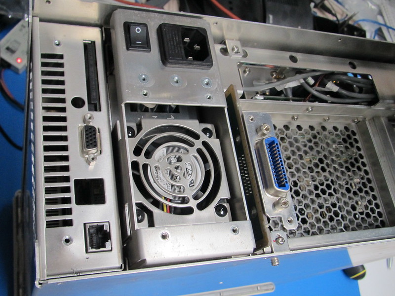
The module on the left is the PC module, the one on the right with the mains entry is the PSU.

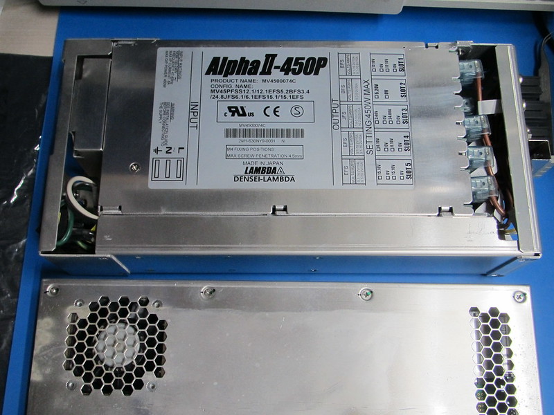
The power supply and PC modules removed. The power supply is build around a standard power supply from Lambda.

The PC and power supply slots:
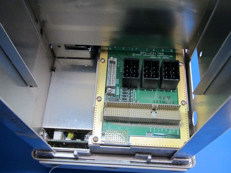
It is hard to see in the picture but there are some bodges on this board.

Inside the PC module:
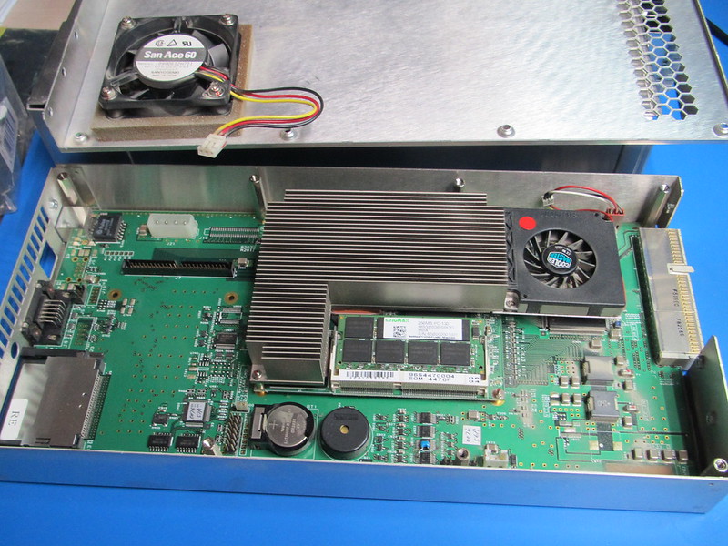
There is a fan which draws air into the module but also a fan which forces air through a large heatsink. Under the heatsink there seems to be a standard embedded PC module which is mounted onto a carrier board. On the left it looks like there is room for a standard hard drive but the (2mm pitch) connector has 50 pins instead of 44. Do I spot another botch?
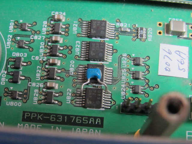
Someone must have had a very steady hand to solder a capacitor on a TSOP (0.65mm pitch) chip!

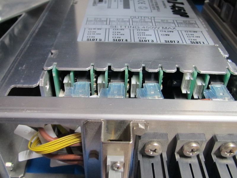
A close-up of the power supply's output section. It is pretty crammed!

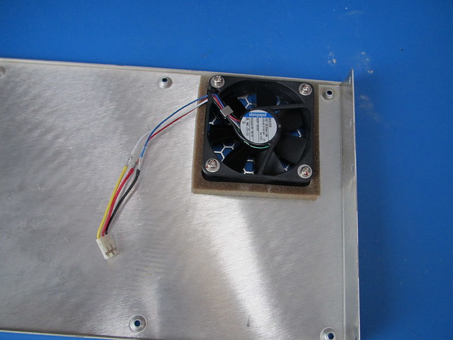
Back to the problem at hand. I decided to replace the fans for the PC module and the PSU anyway. The cooler master (Sunon) fan seemed to run fine (although it makes a lot of noise). The big fan to cool the RF section also seemed fine and doesn't make much noise anyway. I tried to select fans with equal or better airflow / pressure ratings and lower noise levels. I would have liked to replace the (noisy) Cooler Master fan as well but it looks like I would need to remove the heatsink on the PC board and that probably would also disturb the heat conducting rubber.

The new PC module fan. Unfortunately I had to get creative with the wiring. I didn't choose a very high end fan for the PC module even though it is a Papst:

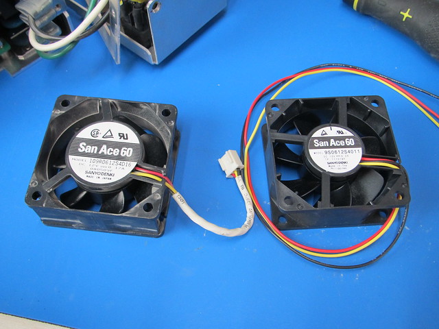
PSU fans (old and new). As a replacement I selected a fan with a slightly higher RPM and pressure rating because I already noticed the PSU gets quite warm (at 76% typical efficiency that is not a surprise!). The original fan seems to be no longer available anyway.

Instead of the original mounting clips I decided to use rubber vibration dampening fan mounts:
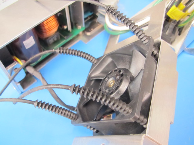

Time to put it back together... unfortunately the fan exchange made the problem worse! Now it always shuts down after a minute or so :palm: After checking the tacho signals (connected a 1k Ohm pull-up from the positive supply to the tacho output) from the fans in the PC module and the big fan in the rear the problem pointed towards the PSU. So I compared the tacho signals from the old and new PSU fan. It turned out the old fan from the PSU doesn't output a tacho signal at all but commutation noise seemed to indicate the tacho should be around 150Hz. The new fan however runs faster and outputs 163Hz. As a test I decided to defeat the PSU fan failure signal and BINGO! No more 'Warning fan 4 failed' messages. Time to open up the power supply and look for obvious problems. Even though the new fan had been running for a short while in the PSU the tacho signal still worked so at least the PSU hadn't killed the tacho output.

Oh crap... that is crowded!
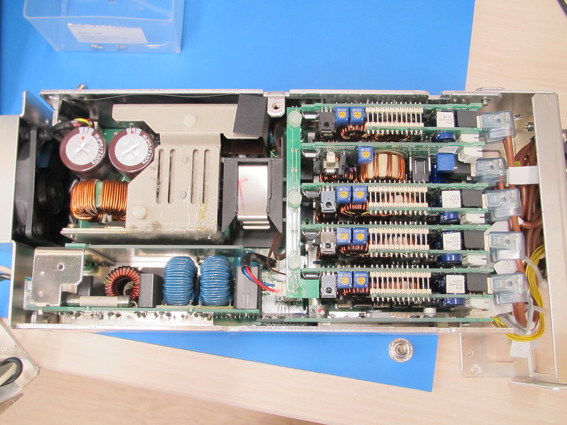
But... actually it is constructed quite cleverly. The black block (with metal clip) in the middle is the transformer. The PCB in the top left is the switching/control board, the PCB in the bottom left is the mains filter and the PCBs on the right are the output modules. At the bottom right there is also a PSU status board with an isolated power supply to provide a floating status signal. From what I have seen it is possible the remove the mains filter (which can be pulled out). After that the switching / control board can be unscrewed and pulled out to the left (the transformer is connected to the switching/control board with a connector and stays inside the PSU). However I didn't go that far! I measured whether the PSU had a short between the fan power supply and the tacho signal but that wasn't the case (measured 1.8 kOhm). I also did some checks on the PSU status board but nothing stood out. My guess is that the PSU checks whether the fan speed is within a certain margin and throws an error if it isn't. After some throught I decided to leave the fan failure signal open (defeated) since the PSU also has an over temperature protection. 'Fixing' the PSU would be a major undertaking and if it does rely on the fan operating within a small RPM range I rather do without that because things like that cause more problems than they solve.

I did modify the PSU a little though. There is an aluminium frame around the PSU to make it fit and hold the various connectors. Along the side there is an open duct which could allow the PSU to suck air from the fan exhaust which would basically mean the PSU is trying to cool itself with hot air. I decided to close the duct so it can't suck in hot air from the rear. I also tied the wires coming from the PSU together to (hopefully) improve airflow.
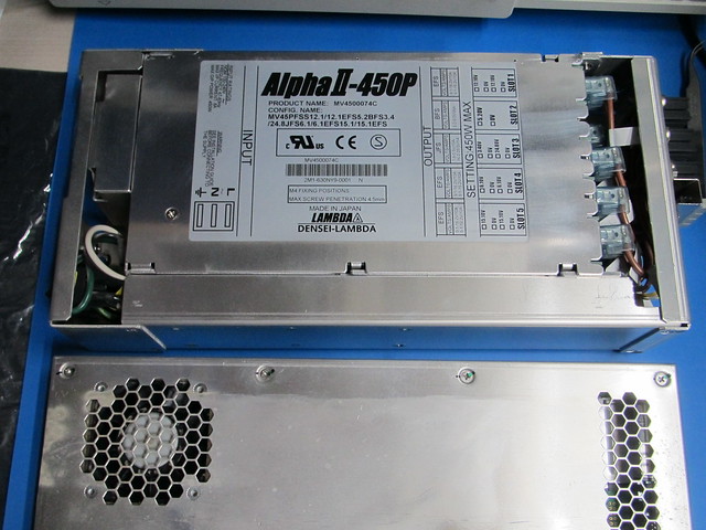

After putting a couple of dozen screws back (fortunately there are only 2 different types) the R3477 worked as it should! It is still noisy though mostly due to the small Cooler Master fan in the PC module.
« Last Edit: July 26, 2016, 10:01:10 pm by nctnico »
There are small lies, big lies and then there is what is on the screen of your oscilloscope.
 
The following users thanked this post: Wuerstchenhund

Offline AF6LJ

  • Supporter
  • ****
  • Posts: 2902
  • Country: us
Re: Advantest R3477 9kHz to 13GHz spectrum analyzer
« Reply #9 on: July 27, 2016, 12:47:11 am »
Cool making progress.
Sue AF6LJ
 

Offline nctnicoTopic starter

  • Super Contributor
  • ***
  • Posts: 26906
  • Country: nl
    • NCT Developments
Re: Advantest R3477 9kHz to 13GHz spectrum analyzer
« Reply #10 on: August 15, 2016, 03:03:54 pm »
I'm trying to contort the R3477 into making dumps of the sampled IF data (no luck so far) but I did find something interesting with the debugger! The code to enter the service mode: 17320504
That at least allowed me to read the number of power on cycles (1060 ish) and the number of hours it was on (730). Ofcourse lots of menus to adjust stuff as well but I stayed away from those.
« Last Edit: August 15, 2016, 03:12:47 pm by nctnico »
There are small lies, big lies and then there is what is on the screen of your oscilloscope.
 

Offline Wuerstchenhund

  • Super Contributor
  • ***
  • Posts: 3088
  • Country: gb
  • Able to drop by occasionally only
Re: Advantest R3477 9kHz to 13GHz spectrum analyzer
« Reply #11 on: August 16, 2016, 05:09:27 pm »
Just curious, where did you get these rubber mounts from?


I searched around but I only ever find the simpler ones which have one or maybe two stops.
 

Offline nctnicoTopic starter

  • Super Contributor
  • ***
  • Posts: 26906
  • Country: nl
    • NCT Developments
Re: Advantest R3477 9kHz to 13GHz spectrum analyzer
« Reply #12 on: August 16, 2016, 06:37:27 pm »
Just curious, where did you get these rubber mounts from?

From Farnell (a pack of 50):
uk.farnell.com/duratool/dtrfmm-1/fan-mount-universal-4-5mm-pk50/dp/2472730
Unfortunately they seem to be out of stock at the moment.
There are small lies, big lies and then there is what is on the screen of your oscilloscope.
 

Offline Muxr

  • Super Contributor
  • ***
  • Posts: 1369
  • Country: us
Re: Advantest R3477 9kHz to 13GHz spectrum analyzer
« Reply #13 on: August 16, 2016, 06:55:13 pm »
Nice progress! I ordered a pack of those dtrfmm-1 from Amazon here in the US. I might be looking to replace some fans on my FSEA30 as well.
 

Offline nctnicoTopic starter

  • Super Contributor
  • ***
  • Posts: 26906
  • Country: nl
    • NCT Developments
Re: Advantest R3477 9kHz to 13GHz spectrum analyzer
« Reply #14 on: August 17, 2016, 01:24:11 pm »
@Muxr: Your FSEA30 is a good catch as well!  :-+
There are small lies, big lies and then there is what is on the screen of your oscilloscope.
 
The following users thanked this post: Muxr

Offline cncjerry

  • Supporter
  • ****
  • Posts: 1283
Re: Advantest R3477 9kHz to 13GHz spectrum analyzer
« Reply #15 on: August 17, 2016, 09:07:13 pm »
Hey nctnico, when are you going to post more pictures?  I'm thinking about one of the analyzers.
 

Offline nctnicoTopic starter

  • Super Contributor
  • ***
  • Posts: 26906
  • Country: nl
    • NCT Developments
Re: Advantest R3477 9kHz to 13GHz spectrum analyzer
« Reply #16 on: August 17, 2016, 09:32:37 pm »
Hey nctnico, when are you going to post more pictures?  I'm thinking about one of the analyzers.
What kind of pictures would you like? I think I have shown more of the inside than I wanted to already  :P
There are small lies, big lies and then there is what is on the screen of your oscilloscope.
 

Offline cncjerry

  • Supporter
  • ****
  • Posts: 1283
Re: Advantest R3477 9kHz to 13GHz spectrum analyzer
« Reply #17 on: August 18, 2016, 01:17:22 am »
I'm looking more for signal work, primarily how it does with low level signals. Also, a very low RBW (averaged) of the calibration signal with a span of 1.2Khz.  I would like to see how the line noise sidebands look.  One of the issues with my 8568B and 8566B is the noise sidebands are more prominent than I would like.  So with a -10dBm signal from the calibration port, you can see very small peaks at +/- 120hz.  The peaks on my 8568B are down about 100dBc and the 8566B are -92dBc.  The 8566B started out really bad (-72dBc) until I reworked the cable paths adding a steel plate between the cables and transformer inside the analyzer.  It was recently one of the longer threads on HP/Agilent group.  I would like to see how much better the Advantest does. withj internal line noise.

So any low level (or even high level) signals with a 10hz RBW and a span of 1.2K would be helpful.  On the 8568 and 8566 you have to VBW average to see the low level line noise peaks.

Thanks
 

Offline nctnicoTopic starter

  • Super Contributor
  • ***
  • Posts: 26906
  • Country: nl
    • NCT Developments
Re: Advantest R3477 9kHz to 13GHz spectrum analyzer
« Reply #18 on: August 18, 2016, 11:47:36 pm »
I tried to find those spikes (I'm in 50Hz country so I guess I would be looking at 100Hz sidebands) but I can't see them. First I tried the calibrator output but that seemed to have a lot of noise. Then I tried a -70dBm 100MHz sine wave (from an HP E4421B) so I only get the noise from the SA itself but still no spikes.
There are small lies, big lies and then there is what is on the screen of your oscilloscope.
 

Offline rf-loop

  • Super Contributor
  • ***
  • Posts: 4105
  • Country: fi
  • Born in Finland with DLL21 in hand
Re: Advantest R3477 9kHz to 13GHz spectrum analyzer
« Reply #19 on: August 19, 2016, 06:42:04 am »
I tried to find those spikes (I'm in 50Hz country so I guess I would be looking at 100Hz sidebands) but I can't see them. First I tried the calibrator output but that seemed to have a lot of noise. Then I tried a -70dBm 100MHz sine wave (from an HP E4421B) so I only get the noise from the SA itself but still no spikes.

Your marker is around -80dBc in first image  and in previous msg cncjerry talk aput -100dBc peaks. Your noise level is 20dB over this level where he look sideband peaks.  Next image your marker is around -60dBc  if 50Hz modulation sidebands are at this level it mean quite high 0.2% (am) modulation.  If you see there in this case 50Hz sidebands ...well...something is failed and need repair. :-DD
« Last Edit: August 19, 2016, 06:47:53 am by rf-loop »
I drive a LEC (low el. consumption) BEV car. Smoke exhaust pipes - go to museum. In Finland quite all electric power is made using nuclear, wind, solar and water.

Wises must compel the mad barbarians to stop their crimes against humanity. Where have the wises gone?
 

Offline cncjerry

  • Supporter
  • ****
  • Posts: 1283
Re: Advantest R3477 9kHz to 13GHz spectrum analyzer
« Reply #20 on: August 19, 2016, 06:50:51 am »
Nctnico, no, that's really clean.  If you are in the UK at 50hz, I would think if they were there you would see them at +/- 100 or 150.  So your shielding and supply is pretty clean. 
 

Offline nctnicoTopic starter

  • Super Contributor
  • ***
  • Posts: 26906
  • Country: nl
    • NCT Developments
Re: Advantest R3477 9kHz to 13GHz spectrum analyzer
« Reply #21 on: August 19, 2016, 09:18:05 am »
I tried to find those spikes (I'm in 50Hz country so I guess I would be looking at 100Hz sidebands) but I can't see them. First I tried the calibrator output but that seemed to have a lot of noise. Then I tried a -70dBm 100MHz sine wave (from an HP E4421B) so I only get the noise from the SA itself but still no spikes.
Your marker is around -80dBc in first image  and in previous msg cncjerry talk aput -100dBc peaks. Your noise level is 20dB over this level where he look sideband peaks.  Next image your marker is around -60dBc  if 50Hz modulation sidebands are at this level it mean quite high 0.2% (am) modulation.
It seems to me the noise is coming from the signal sources I used so if there are 50Hz modulation sidebands they are masked by the noise from the signal sources. I think I need a cleaner signal source for this test to get a better signal to noise ratio.
There are small lies, big lies and then there is what is on the screen of your oscilloscope.
 

Offline Wuerstchenhund

  • Super Contributor
  • ***
  • Posts: 3088
  • Country: gb
  • Able to drop by occasionally only
Re: Advantest R3477 9kHz to 13GHz spectrum analyzer
« Reply #22 on: August 19, 2016, 10:24:18 am »
It seems to me the noise is coming from the signal sources I used so if there are 50Hz modulation sidebands they are masked by the noise from the signal sources. I think I need a cleaner signal source for this test to get a better signal to noise ratio.

If you have access to a 10Mhz Reference source like a GPSDO or Rb source try this. They usually come with a lot less noise than the old HP ESG Series generators.
 

Offline nctnicoTopic starter

  • Super Contributor
  • ***
  • Posts: 26906
  • Country: nl
    • NCT Developments
Re: Advantest R3477 9kHz to 13GHz spectrum analyzer
« Reply #23 on: August 19, 2016, 06:16:05 pm »
I did some further reading into phase noise and I found a document called 'Spectrum analyser basics' from Agilent. I'm by no means an expert when it comes to spectrum analysers but I like to learn more to have confidence in what I see on the screen. However my typical SA use does not involve anything which has to do with radio communication (so far).
Anyway I did some further testing and decided to see if I could make some meaningful measurement for the phase noise 10kHz from the carrier which seems to be the norm. The R3477's manual doesn't specify the phase noise (at least not directly in dBc). I used 50MHz @-10dBm from my E4421B (yellow) with the 10MHz references connected and the  R3477's internal calibrator output (blue):

I think it is needless to say the E4421B's output is noisy indeed but that may be caused by my self made output amplifier.

I did find some peaks in the blue trace and put some markers on them. However they don't quite match the mains frequency although you could argue there are some small peaks which could be mains frequency related:

« Last Edit: August 19, 2016, 06:22:46 pm by nctnico »
There are small lies, big lies and then there is what is on the screen of your oscilloscope.
 

Offline cncjerry

  • Supporter
  • ****
  • Posts: 1283
Re: Advantest R3477 9kHz to 13GHz spectrum analyzer
« Reply #24 on: August 19, 2016, 06:31:21 pm »
So is the blue trace the average?  The 52 offset could be line related.  The 74 could be a slight oscillation in the voltage regulator.  I've had a hell of a time removing those regulator sidebands with decoupling.


Share me

Digg  Facebook  SlashDot  Delicious  Technorati  Twitter  Google  Yahoo
Smf