It's been a while since I posted any teardown of T&M gear. Well, wait no more. This time teardown is not about some voodoo expensive bit of metrology gear, but something than any mortal can afford.
Today we'll take a look on little japanese meter that friend of mine brought in for a quick check. This DMM is designed to compete against Fluke 45 dual-display DMM.

Essentially this article shows one example of what you can get for 30-50$ from second-hand market like eBay/taobao etc. Unit was sold as "working" so will see how much of that is true.
Interesting point for Advantest R6452A - use of dual input A/D converter path to perform independent measurement of two signals. These multimeters are targeted for lab/ATE measurement and device testing by configuring as versatile measurement system. The channel A has measurement functions including DCV/DCI, ACV/ACI, two-wire resistance and frequency, while the channel B has DCV/DCI and ACI. There is also input port at the rear for Type K thermocouple temperature measurements.
Today R6452A meters are long obsolete and replaced by newer
ADCMT 7352A model which have slightly better specifications, modern USB interface, but follows same design concept and targeted market.
Key features:
* Maximum display : 199999/199999 counts, 5.5-digit resolution
* Measurement function : DCV, ACV, DCI, ACI, 2w-resistance, low-power resistance, Frequency, Diode, Continuity (A channel), DCV,DCI,ACI (B channel)
* Rear input: Thermocouple Type K temperature
* Sampling rate: FAST: 80 SPS, MED: 10 SPS, SLOW: 2.5 SPS
* Base range : 2 VDC
* DC voltage measurement best accuracy: 180ppm + 5 digits, Resolution: 1 uV (Ach/Bch)
* DC current measurement range : 200mA and 10A
* AC voltage measurement: 20Hz to 100kHz, 200mV - 700V ranges
* AC current measurement: 20Hz to 5kHz, 200mA and 10A ranges
* Interface : RS232, optional GPIB
* Form-factor : Half-width 19" 2U rack or benchtop
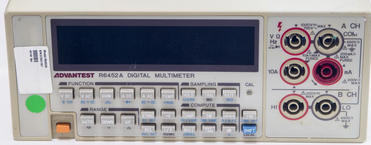
Those input jacks that Advantest uses are super-fragile, and really one of the worst jacks on any instruments we ever used. Same poor jacks used in
8.5-digit R6581 so it's common for Advantest instruments. Red color fused current input jack accepts only maximum 200mA input, so be sure not to supply too much current, or you will have to find new 5mm 200mA glass fuse. Don't ask how I know...

Buttons on the front panel are tiny, and some of the labels are rather cryptic, like SM or MD. Having no public manuals in English also does not help understanding meter operation.
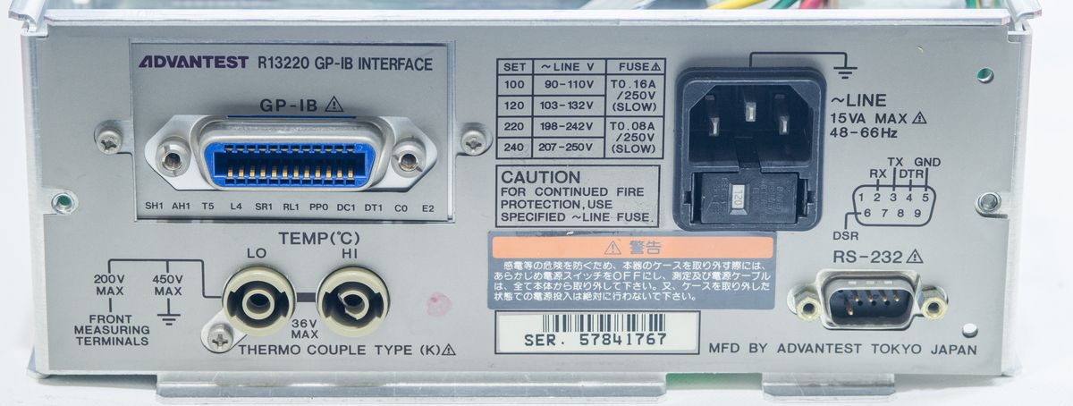
This particular instrument came with GPIB option, but standard unit supplied only with RS232 interface. Banana jacks on the rear dedicated for thermocouple connections only. Unit have mains voltage selector block combined with protection mains fuse. All Advantest instruments are manufactured in Japan.
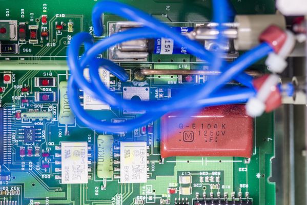
Manuals and comparison to production standardsAdvantest R6451A and R6452A datasheet with specsAdvantest R6451A and R6452A specifications, Japanese languageAdvantest R6451A and R6452A GPIB command matrix, Japanese languageAdvantest R6451A and R6452A operating manual, Japanese languageAdvantest R6451A and R6452A catalog, Japanese languageDesign and constructionRemoving two screws and pulling cover off reveals simple assembly and internal design.
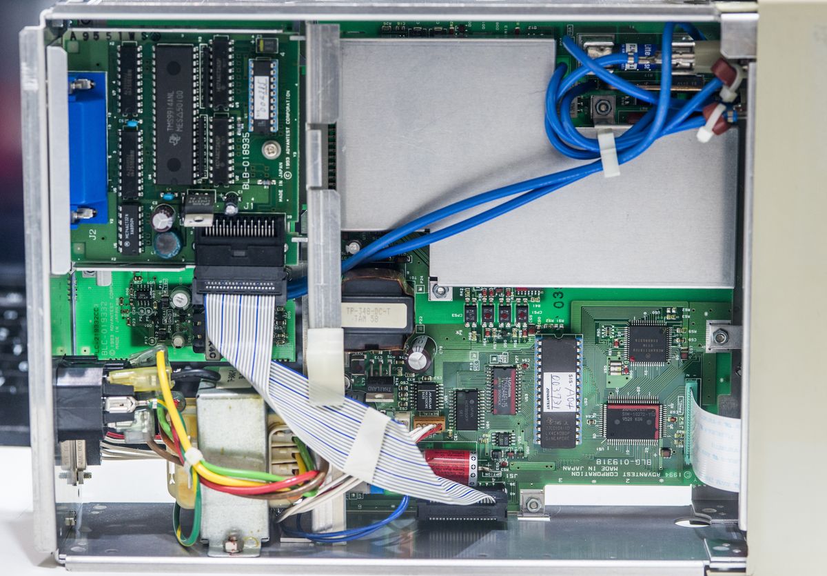
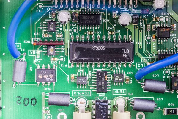
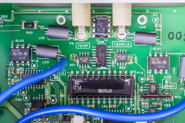
Blue cables going across the instrument are from input jacks. Ribbon cable carry digital signals between out-guard CPU section and GPIB interface board. Advantest have also other options for integrating R6452A into automated test jigs and even optional battery +12V pack to provide standalone operation. There are not that many 5.5-digit DMMs that can be powered from battery, which can be useful in field work.
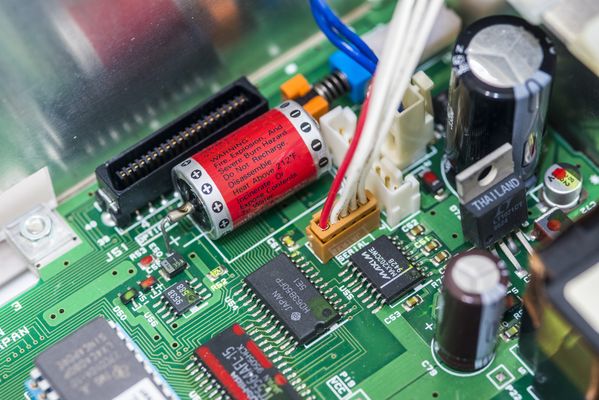
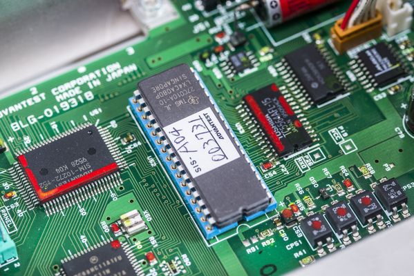
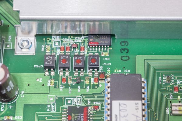
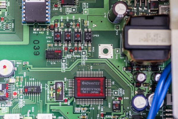
As typical with many other benchtop DMMs, this one also based around Motorola RISC processor, Motorola MC68HC11A to be precise. There is also custom Advantest ASIC next to it, with label SIM-10272-152 doing glue logic and front panel communication. Socketed firmware ROM is TMS27C010A-10 in ceramic DIP package.
Other than little board mod diode, there are no components populated on the bottom side. One can find function switch relays and protection circuits near the input cable connections.
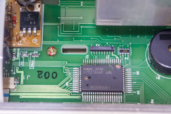
RS232C level translation handled by Maxim MAX202CWE and UART controller Hitachi HD63B50P. Power regulator is located nearby, Linear LT1071CT. Date codes on IC suggest manufacturing date around 30th week of 1995. Battery help to retain SRAM contents with instrument readings and settings. Hopefully calibration data is stored in non-volatile memory, perhaps small SOIC-8 chip with 953B marking?
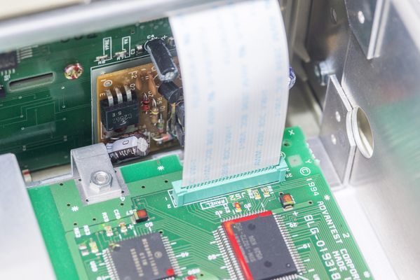
High-voltage DC/DC converter located on small daughter board right on the front panel PCB. This is required to generate proper levels for VFD screen operation.
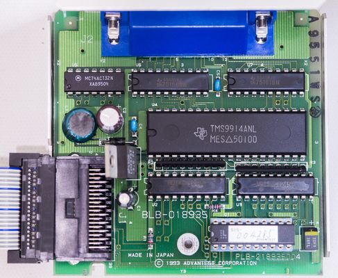
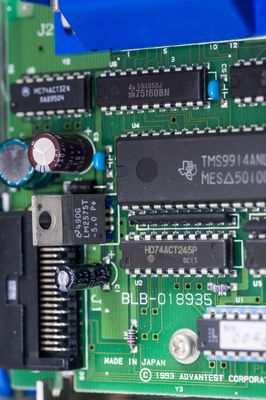
GPIB card using industry standard TMS9914 controller, some digital logic latches and 75160/75161 GPIB drivers. Small Lattice PAL/GAL device handle interrupts and dataflow.
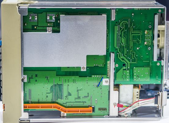
Analog front-end sectionTime to remove aluminum shield from analog section and study overall design.
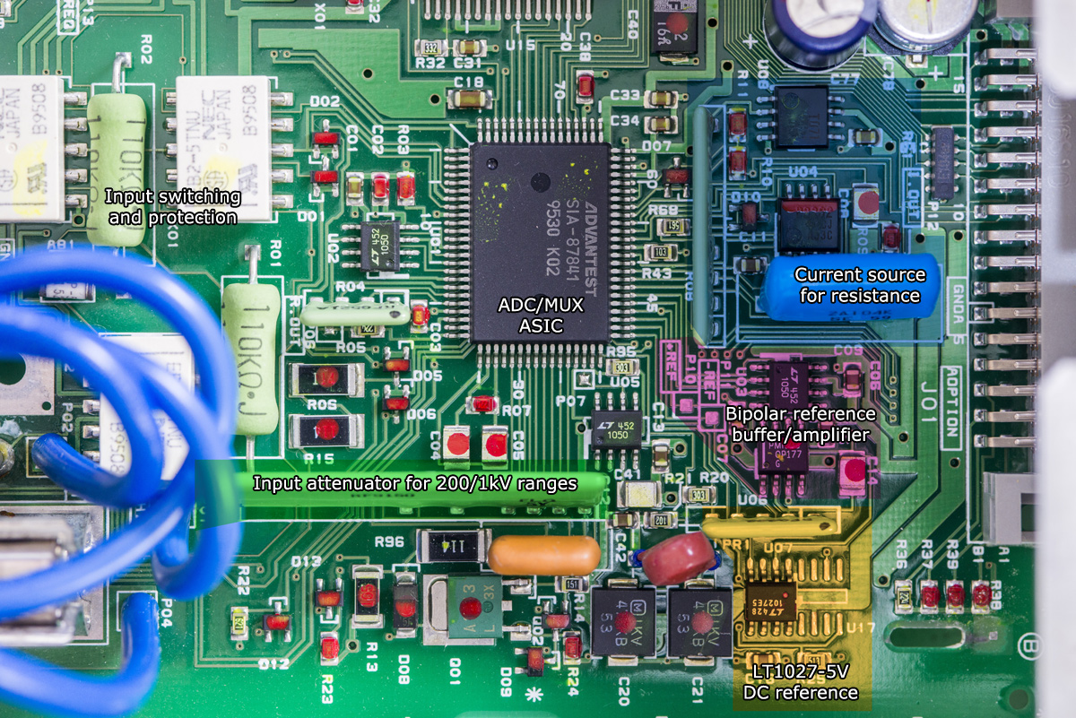
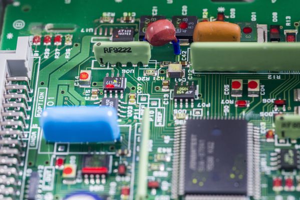
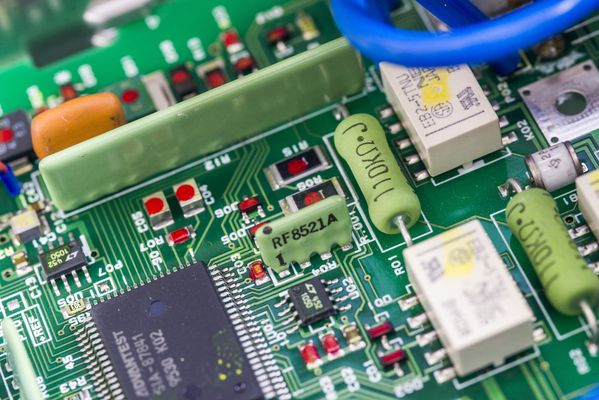
ADC and control of the analog functions is implemented by custom Advantest ASIC, with label SIA-87841. There are lot of
Linear LTC1050 chopper opamps around as well. Green epoxy resistor networks maintain accurate and stable ratios between various signals. One of these resistors used as high-voltage divider for 200V and 1kV ranges.
A/D converter input range is +/-2V. As result input resistance >1 GOhm is provided only for 200mV and 2V ranges, while higher ranges are using 10 MOhm input divider.
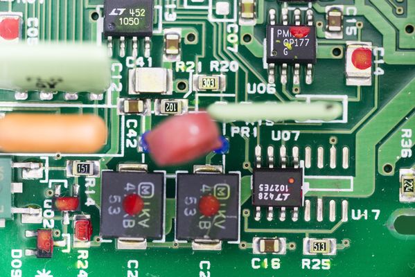
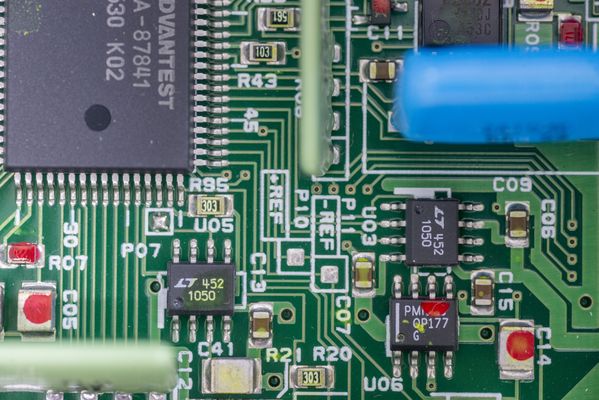
Main reference is
Linear LT1027 that specified to provide +5V with TC stability 2ppm/K and low 1ppm peak noise. It can source 15mA or sink 10mA and as result can be used directly to ADC input without buffering.
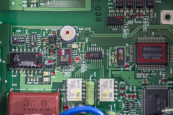
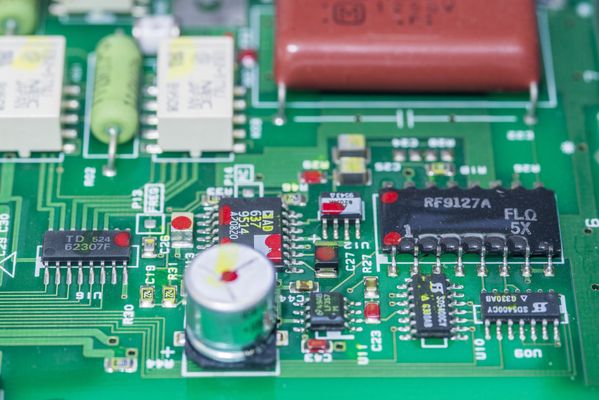
AC RMS conversion is handled by widely known chip for the purpose, AD637. Same chip we can find in other benchtop meters, even high-performance type such as
Keithley 2001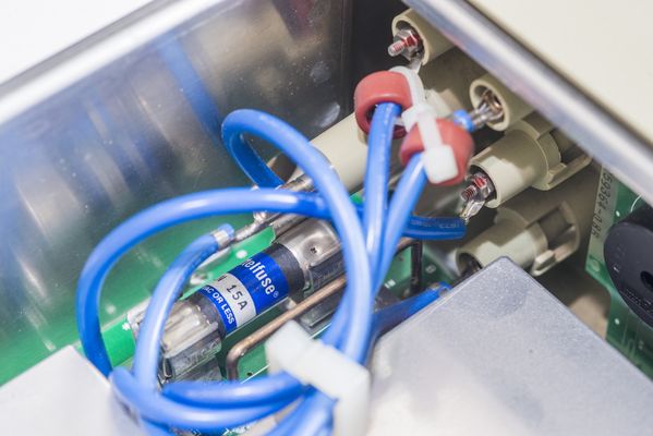
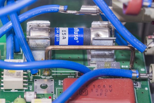
10A current input protected by high-quality HRC 15A Littelfuse fuse, placed on the socket for easy service. 0.1 Ohm shunt is standing right next to the fuse, with smaller 1 Ohm SMT-type shunt located under it. There are no low current ranges on this DMM, so current measurement function is rather simple.
Interfacing between floating analog domain section and earth-referenced digital outguard section done thru four PC817 optocouplers. This means that communication between the processor and analog chipset is done serially thru some kind of SPI or UART-alike interface.
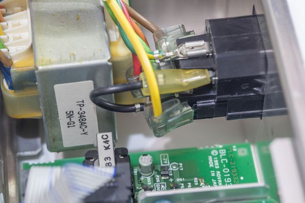
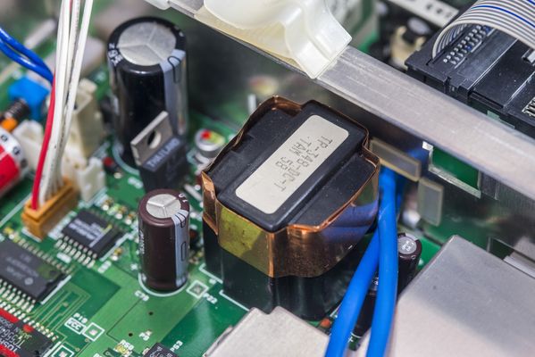
Power is provided thru isolation transformer TP-348-DC-T. Mains transformer bears similar marking, with AC-T ending. Both transformers are unique to Advantest and custom made for this DMM.
There are no components on the back of the PCBA.
h3. Thermocouple rear input assembly
Thermocouple input at the rear using own PCBA, interconnected thru DIN-type connector with mainboard. Input terminals have proper
thermocouple cold-junction compensator LT1025, that provide 0.5 °C initial accuracy for correct Type K probe measurements. There are four more LTC1050 chopper opamps, large black epoxy resistor network and few analog 4052/4053 switches to route signal for ADC.
Calibration testTo test performance of the meter and compare to the specifications we will utilize what is available in my lab:
* Fluke 5720A for DCV, ACV, DCI, ACI and Resistance tests. Calibrated February 10, 2019
* Fluke 5720A + 5725A amplifier for 10A DCI and ACI tests. Calibrated February 10, 2019
*
Keysight 3458A as reference standard for calibrator verification
*
Wavetek 4920M as reference meter for calibrator verification
* Set of shielded Fluke 5440A-7002 cables with copper low-thermal dual banana connectors
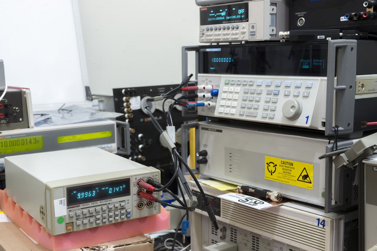
Calibrator was artifact calibrated to reference standards just a 19 days ago, but at accuracy levels of R6452A that is completely unnecessary. Even annual specifications of Fluke 5720A provide good TUR to meet all specifications of this DMM so the calibrator tested just to provide good confidence in results. Ambient temperature was kept at +23 °C +/-1 °C.
No adjustments were performed for this DMM and the original calibration date/time is unknown.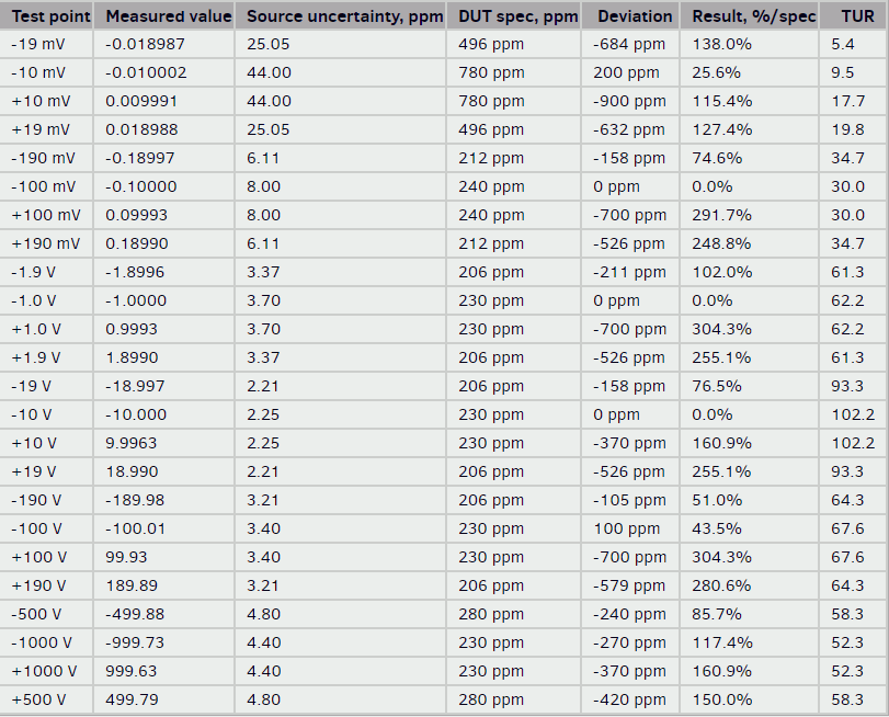
From DC Voltage test results meter is unable to meet it's specifications and need to be adjusted.
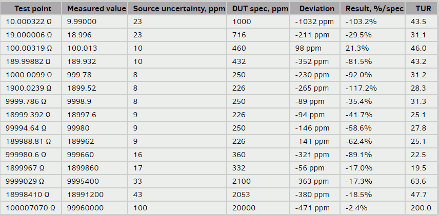
Resistance results are not as bad as DC Voltage, however 2KOhm range could use some adjustment help.
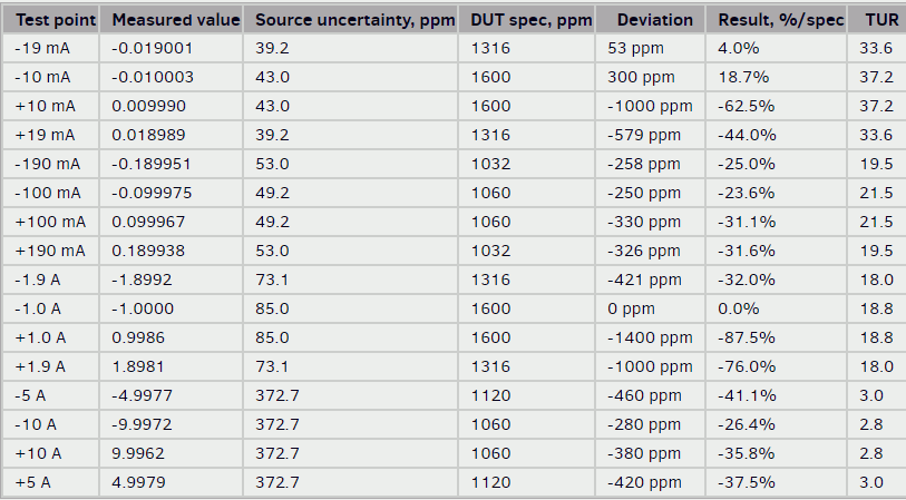
To surprise, DC current function is still in spec, even when measuring current at mere 5% of the scale!
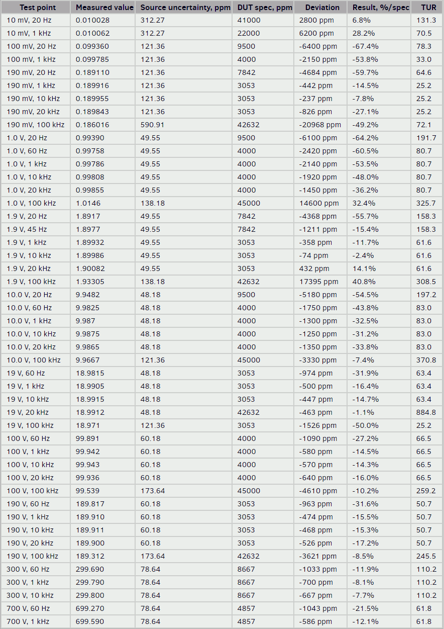
AC Voltage is also okay, meeting specs with decent margin on most of the points.
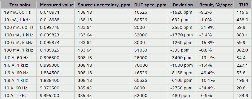
AC Current show no problems either.
DCV linearity verificationR6452A 20VDC range linearity test, using -11 to +11V DC.

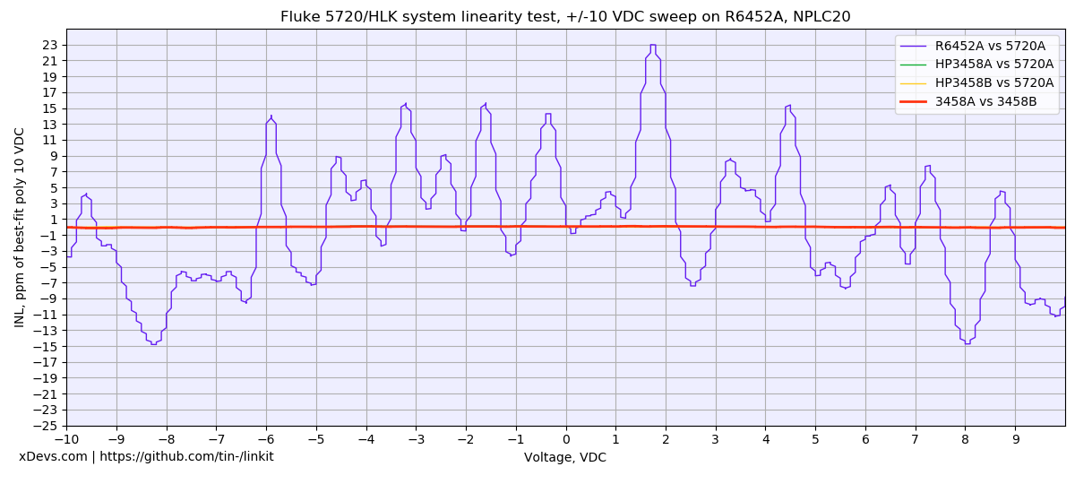
There is no linearity specification in the datasheet, so we can assume this spec to be +/-25 ppm based on the counts error specified for the range. Ideally we should have tested 2V range, but since typical precision application commonly used 10V, tested was performed using -11.0 to +11.0 sweep.
Not to bad for little cost this meter had, and after adjustment it should be able to meet it's specs, however that is the story for another time.

And of course this article (and many others) also
available on my site.


