Author Topic: Comparing an active probe to passive probes for fun  (Read 3950 times)

0 Members and 1 Guest are viewing this topic.

Offline TheSteveTopic starter

  • Supporter
  • ****
  • Posts: 3753
  • Country: ca
  • Living the Dream
Comparing an active probe to passive probes for fun
« on: August 28, 2016, 08:29:19 am »
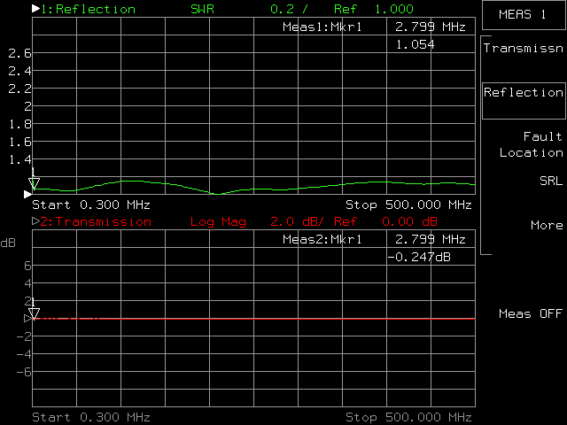
I recently bought my first active probe. I thought I'd have a little fun with it and look at a transmission line using it and some passive probes. To do this I looped coax cables between the source and reflection ports of my network analyzer(HP8714C). There is a T in the center allowing us to probe the signal. The network analyzer was configured to sweep 0.3-500 MHz. It is displaying reflection(SWR) in green and attenuation(dB) in red - a very basic way to see what effect the probe has on the signal.

This is the baseline signal with nothing connected to the transmission line.

This is a Tektronix P6139B 500 MHz 10Mohm 8pF passive probe connected to the transmission line.


This is an Agilent 1160A 500 MHz 10Mohm 9pF passive probe connected to the transmission line.


This is an Agilent 1161A 500 MHz 10Mohm 10pF passive probe connected to the transmission line.


And finally the Agilent N2795A 1GHz 1Mohm 1pF active probe connected to the transmission line.


Edit Sept 18, 2016 to add Agilent 1152a 2.5 GHz 100k ohm 0.6 pF active probe connected to the transmission line.


All probes were connected using the probe tip and a ground spring to minimize inductance/loading.

As the capacitance increases it is easy to see how much more loading there is with the passive probes, and it is easy to see how little impact the active probe has on the signal.

I don't know if Dave has any active probes but it a video on probe loading might be interesting.

« Last Edit: September 18, 2016, 08:08:06 am by TheSteve »
VE7FM
 

Offline Gandalf_Sr

  • Super Contributor
  • ***
  • Posts: 1729
  • Country: us
Re: Comparing an active probe to passive probes for fun
« Reply #1 on: August 28, 2016, 09:34:02 am »
Interesting, I wonder how bad things would have got on the passive probes if you'd been able to go up to 1 GHz.  I also wonder how my poor man's probe-based FET probe would fare.
If at first you don't succeed, get a bigger hammer
 

Offline TheSteveTopic starter

  • Supporter
  • ****
  • Posts: 3753
  • Country: ca
  • Living the Dream
Re: Comparing an active probe to passive probes for fun
« Reply #2 on: August 28, 2016, 09:45:40 am »
I can go higher in frequency but it didn't really seem fair as the passive probes are all rated to 500 MHz and wouldn't be very useful to actually look at the signal on the scope. If I get a chance tomorrow I'll try putting a 10pF cap in place of a probe and see how it compares.
VE7FM
 

Offline tggzzz

  • Super Contributor
  • ***
  • Posts: 19511
  • Country: gb
  • Numbers, not adjectives
    • Having fun doing more, with less
Re: Comparing an active probe to passive probes for fun
« Reply #3 on: August 28, 2016, 02:41:06 pm »
I can go higher in frequency but it didn't really seem fair as the passive probes are all rated to 500 MHz and wouldn't be very useful to actually look at the signal on the scope. If I get a chance tomorrow I'll try putting a 10pF cap in place of a probe and see how it compares.

Try a "low impedance" *10 probe as well; typically they are 500ohm//0.7pF, or 1kohm//0.7pF.

You could make one by having two back-to-back jacks (BNC/SMA/as appropriate) where the shield is "well connected" and there is a 470ohm resistor between the two jacks' centrepins. (Ideally 450ohm, but for the experiment 470ohm will have a predictable difference).
There are lies, damned lies, statistics - and ADC/DAC specs.
Glider pilot's aphorism: "there is no substitute for span". Retort: "There is a substitute: skill+imagination. But you can buy span".
Having fun doing more, with less
 

Online David Hess

  • Super Contributor
  • ***
  • Posts: 16619
  • Country: us
  • DavidH
Re: Comparing an active probe to passive probes for fun
« Reply #4 on: August 28, 2016, 09:17:28 pm »
There is a T in the center allowing us to probe the signal.

What kind of T adatper?

I have done the same thing using a BNC-T and coaxial BNC to probe tip adapter but only up to 300 MHz.  They are hard to find but they make (or used to make) special T adapters which have the probe tip adapter built in so the transmission line stub is as short as possible.
 

Offline TheSteveTopic starter

  • Supporter
  • ****
  • Posts: 3753
  • Country: ca
  • Living the Dream
Re: Comparing an active probe to passive probes for fun
« Reply #5 on: August 29, 2016, 03:13:09 am »
I am using a regular BNC T with some short RG142 coax jumpers. Far from ideal which is why I suggested this was just for fun. I have also considered creating a PCB open transmission line or even just taking a RG142 jumper and making a small hole in the shield/insulation so I can probe the center conductor. I replaced the T with a BNC through adapter and the pattern is certainly not better - below 500 MHz anyway.

I tried creating a budget 500 ohm 10:1 probe using a 4 foot length of RG142 with BNC's on both ends. I then connected a female-female BNC adapter and used a standard 1/4 watt 470 ohm resistor coming off the end with a short lead. It performs quite well(especially for the price!), you can see the reflections it creates as well as its loading from being 500 ohms. I measured the capacitance of the probe which is ~ 1pF according to my Agilent U1733C. This is basically a very budget recreation of an Agilent 1163A(which I am on the lookout for).


And a pic of the various probes:
« Last Edit: August 29, 2016, 03:26:22 am by TheSteve »
VE7FM
 

Online David Hess

  • Super Contributor
  • ***
  • Posts: 16619
  • Country: us
  • DavidH
Re: Comparing an active probe to passive probes for fun
« Reply #6 on: August 29, 2016, 04:25:24 am »
I am using a regular BNC T with some short RG142 coax jumpers. Far from ideal which is why I suggested this was just for fun. I have also considered creating a PCB open transmission line or even just taking a RG142 jumper and making a small hole in the shield/insulation so I can probe the center conductor. I replaced the T with a BNC through adapter and the pattern is certainly not better - below 500 MHz anyway.

The made-for adapters look like a precision coaxial air line with a chunk taken out of the middle on the side where the probe attaches.  It is sort of like a T adapter with the middle section ground down flush with the through part.  I tried to find some examples but the only ones I know of were made 20+ years ago and the GR874 version was the most common; I guess everbody uses a BNC-T now like you did. :)

The printed circuit board equivalent could be a coplanar waveguide with connectors on either end like you described and a printed circuit probe tip adapter soldered to the middle.  LeCroy and Tektronix sell these probe tip adapters if you want to buy in bulk or you can sometimes find them on Ebay.  They look a lot like the old printed circuit board Peltola connectors.

The other handy adapter is a feedthrough termination with the probe tip adapter built in.  That is what is used to probe bandwidth and performance tests.  A feedthrough termination with coaxial probe tip adapter on the end works at lower frequencies.


Share me

Digg  Facebook  SlashDot  Delicious  Technorati  Twitter  Google  Yahoo
Smf