-
when locked on a (strong enough) signal on band 3, the IF sits at roughly 127.9MHz instead of 125MHz as described in the manual, for which the troubleshooting tree concludes that "VCO or LOCK CIRCUITRY on A108 BAD".
127 MHz is correct, EIP has changed IF frequency in later A203 revisions, all 'B' models are 127 MHz.
You can look at the A203 internal IF amplifier, if I remember correctly at right side looking from front, sometimes I've found some leaking SMD ceramic capacitors. Please DO NOT touch the small wires coming from YIG filter through a hole, these are folded as a kind of inductance during factory calibration.
Check also if the screws holding the YIG filter to A203 box are tighten, sometimes loss of performance happen for these loose screws. -
127 MHz is correct, EIP has changed IF frequency in later A203 revisions, all 'B' models are 127 MHz.
Ghezz, thanks you so much.You can look at the A203 internal IF amplifier, if I remember correctly at right side looking from front, sometimes I've found some leaking SMD ceramic capacitors. Please DO NOT touch the small wires coming from YIG filter through a hole, these are folded as a kind of inductance during factory calibration.
Ok I'll be extra careful! How leaky are we talking about there? like they begin to behave like a resistor on DC? Is probing with an LCR meter is enough to detect them (like the DER DE-5000 I have)?Check also if the screws holding the YIG filter to A203 box are tighten, sometimes loss of performance happen for these loose screws.
I'll give the YIG filter a look too. In fact I've opened the YIG to be able to clean it (enclosure was really rusty, as can been seen on the pictures I posted at the beginning of the thread), so maybe there is some "alignment" that must be taken care of when putting is back together. However, it did have poor sensibility before being taken apart, so...
[mode miracle]Don't you have a copy of the 545B service manual somewhere? It would be so much easier! [/mode miracle]
-
I've opened A201 to make a quick check of capacitors in there, nothing stroke my eye.
But I've also disassembled the YIG filter, and I may have found the reason it works poorly on band 3... and it's probably not a very good news.
I've looked at the YIG spheres (since there are 2 of them in this filter) using my cheap USB microscope.
Top side:
And the bottom side (with copper shim removed):
For which a closer look gives:
on which you may see the problem, more visible on this one:
It's not attached to the "holding rod" any more. Luckily, the cage is small enough for the sphere not to fall, but it not seated at it's correct position either...
Should I try to stick it back to the holder? With what kind of "glue"? For the record, these 2 balls are very small, maybe 2 or 3/10 mm, so it will not be an easy task...
David
-
And in the (probable) case I do not succeed in fixing this YIG filter, any idea what is the "meaning" of the '-09 REVA' on my unit (part number is 2010241-09 REVA)?
There are a few of the on eb, but none have exactly the same part number. For example there is a reasonably cheap 2010241-08 Rev. D available, is there a chance it will work (after recalibration)?
David
-
There are a few of the on eb, but none have exactly the same part number. For example there is a reasonably cheap 2010241-08 Rev. D available, is there a chance it will work (after recalibration)?
"-08" is for 5x8B (26.5 GHz) models, odd numbers are for 20GHz ones, 'B' models start with "-05" (127MHz IF), my informations are too old, I suppose that the "-07" is also for 'B' 20GHz... no idea for Special WB-68 of your unit.Should I try to stick it back to the holder? With what kind of "glue"? For the record, these 2 balls are very small, maybe 2 or 3/10 mm, so it will not be an easy task...
Sorry, I haven't tried any repair at this level, normally the entire A203 converter has to be returned to factory for exchange, in few cases I have repaired the manageable areas, only in one case I have success in repair the MW fllter for a short of COMB drive signal to ground, purely a mechanical issue
If you have the possibility to measure the input RL (VSWR) setting the YIG coil current for a specific tune frequency, you can determine if the coupling between input RF link (that is critical) and the YIG sphere is compromised or not.Ok I'll be extra careful! How leaky are we talking about there? like they begin to behave like a resistor on DC?
Yes, DC leak that affect BIAS of amplifiers stages.Quote[mode miracle]Don't you have a copy of the 545B service manual somewhere? It would be so much easier! [/mode miracle]
I have some in paper form, unfortunately NOT in pdf, another member has already asked me for a manual, at the moment don't have much time to do long and tedious scanning sessions...
-
If you have the possibility to measure the input RL (VSWR) setting the YIG coil current for a specific tune frequency, you can determine if the coupling between input RF link (that is critical) and the YIG sphere is compromised or not.
I do have a spectrum analyzer (Advantest R3465, 8GHz) but no TG (well I do have an R3561L that can be used as TG for the R3465 up to 2GHz, but it also needs repair, the output level jumping all over the place). So I may be able to do some measurement "by hand" (sweeping my RF gen), but not completely sure how to do such a measurement properly (I am mostly a newbie in RF).
What is the best way of setting the YIG current to match a given frequency (bypassing the automatic search mechanism)? I don't see any TEST mode for that. Could the min/max frequency parameters be used to achieve this?I have some in paper form, unfortunately NOT in pdf, another member has already asked me for a manual, at the moment don't have much time to do long and tedious scanning sessions...
oh please! please! please! :-) eg. a few pages at a time. Another solution: send it to me, I do the scanning then I send it back.
David -
Humm this is gone to be pretty tricky I'm afraid. According to these docs:
http://www.microlambdawireless.com/uploads/files/pdfs/ytfdefinitions2.pdf
http://www.microlambdawireless.com/uploads/files/pdfs/ytodefinitions2.pdfQuoteThe YIG sphere is typically mounted on the end of a thermally conductive rod (normally beryllium).
This is done for two reasons: 1) the rod acts as a “tuning stick” for orienting the YIG sphere in the resonant circuit and
2) YIG has best performance when it’s temperature is kept constant.
So (obviously) the YIG sphere must be oriented correctly...
When I look at it under the microscope, I can see the rod's mark on the YIG sphere, so in theory, it may be possible to put it back roughly at its original position/orientation.
This will really be tricky... especially since my cheap USB microscope needs to be really close to the observed device to have high enough magnification, so I won't have a clear path to the YIG sphere... I'll try to move the sphere under microscope with a tiny plastic tip ASAP, just to see if it's actually practicable.
Note that the document describing the principles of a YIG filter do describe a single stage bandpass filter as well as a two-stages band-reject filter, using 2 YIG spheres 'in series'. The topology in the EIP input stage seems to be a 2-stages bandpass filter: each YIG resonator is mounted as a bandpass, with the input and output coupling loops aligned at 90°; both filters being in series (the output of the first one, the one that took off the rod in my device, is the input of the second one, via the wire used as coupling loop over both of them).
-
What is the best way of setting the YIG current to match a given frequency (bypassing the automatic search mechanism)? I don't see any TEST mode for that. Could the min/max frequency parameters be used to achieve this?
I cannot test this right now since the YIG is disassembled on my bench, but I think this is achievable but using TEST10 (memory read/write). According to the SM, it seems possible to directly write into the YIG frequency controller (at addresses 0x1840 and 0x1842); for a desired frequency F (in MHz), just have to write F/2 as hex value in these registers.
For example, if I want to tune the YIG filter to 1200MHz, F/2 is 600, ie. 0x0258 in hex.
So I would have to write:- 0x02 at address 0x1842 and
- 0x58 at 0x1840.
-
but using TEST10 (memory read/write). According to the SM, it seems possible to directly write into the YIG frequency controller (at addresses 0x1840 and 0x1842); for a desired frequency F (in MHz), just have to write F/2 as hex value in these registers.
Yes, the addresses are correct for your new CPU board (old version is 0x984x).
These TEST10 commands are to be inserted just after power up of unit (switch OFF and then ON). -
A quick follow up:
- I've been able to fix the -160MHz offset default setting
- I've been able to partially fix the 5 digits resolution default setting
- I've not yet been able to fix the sensitivity problem
For the default settings, I just replaced a few instructions in the initialization routine by NOPs, as described in https://whatever.sdfa3.org/eip-545b-rf-frequency-counter-part-4.html
The problem with the resolution is that I do have all the digits displayed, but the actual resolution remains on 5 digits; I guess there is also some initialization code that configure the gate generator (A107) to modify accordingly...
For the sensitivity problem, I've not been able to put the YIG sphere in place: it is very hard to manipulate by hand. However, I a wondering if this is the only problem; I also suspect the 15dB boost in A201 to be faulty.
I've picked up the schematic of the A201 board (the IF amplifier/detector part):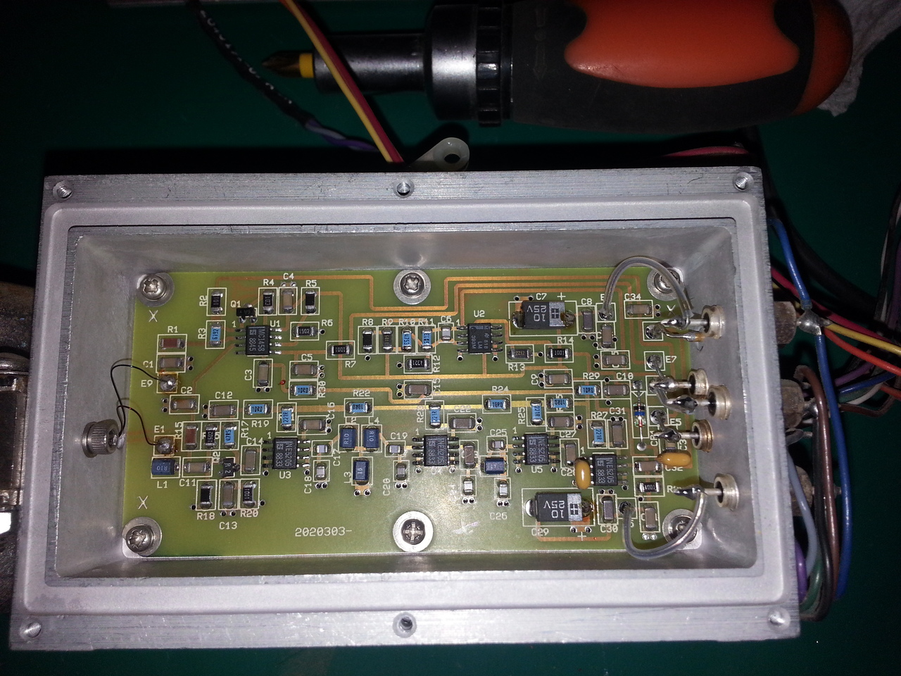

I've been suspecting the Q1 transistor, but I've been fooled by the fact it's a JFET, so it does measure low resistance between the source and the drain when the gate is not high.
I've desoldered it from the board, but it looks to work just fine (cheked with 20$ LCR/transistor meter).
On this schematics, I'm not sure what kind of signal is expected on input E9 (from the YIG): when measuring with a multimeter, I have very low resistance to the ground (maybe 0.2 or 0.3 ohm).
Looking at the output of the YIG, this E9 being the green wire, it looks to be, indeed, connected to the ground on the ceramic board: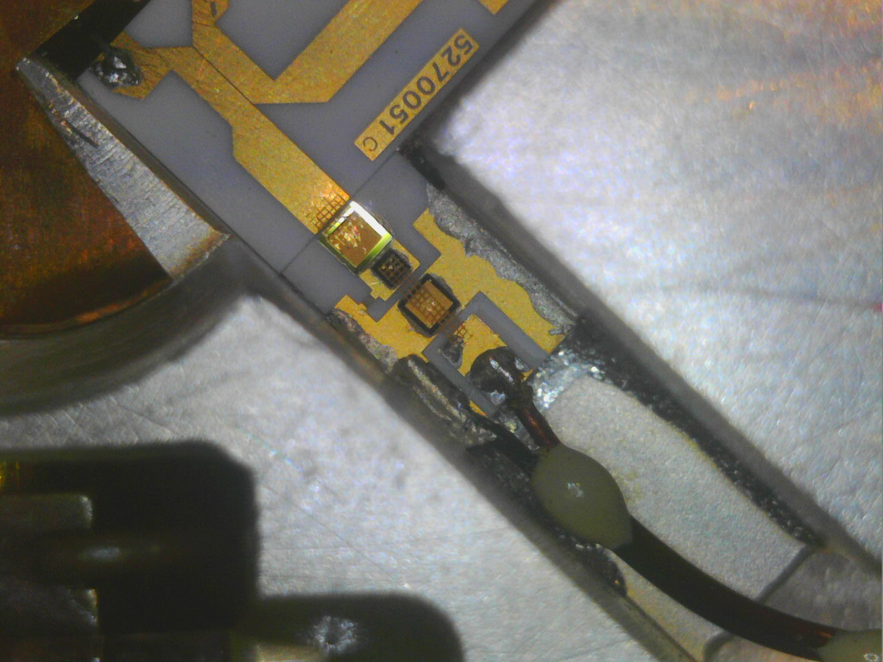
So I guess it should be considered as ground-level (once again, being a noob in RF, I've been fooled by the presence of R1/C1 there (especially R1), as both side of the wire are grounded, but as usual with RF, it's a "transmission line", not an equipotential, so I guess they make sense).
[edit]in fact, when Q1 is blocked, the gain of this amplifier is something like 32 (1+61.9/2), and when the Q1 is on, the gain drops to around 1, so the ~15dB boost controlled by the E7 input.[/edit]
So I need to dig more...
For those playing at home (as Dave would say), here is a picture of the whole ceramic board in the YIG enclosure, including the mixer (the IF signal generated by the VCO arrives on the pin at the top of the picture) :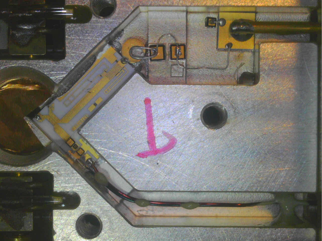
David
-
Hi everyone,
I'm still fighting against this sensitivity problem, and I have hard time understanding how the so called "Video Amplifier" (should) works.
In fact, I'm not sure I do understand the kind of signal and impedance I should expect from the YIG filter assembly. This unit do combine the filter itself (which is known to be partly broken in my unit, as shown earlier), but I'd like to understand a bit better the mixer part.
The mixer looks like the last picture from my previous post.
As far as I understand dit, it consists in two parts:
- the LO path, where there are filtering made of capacitors and inductances (the wire between capacitors) before entering the ceramic circuit, on which lies several stripline-like RF filters ending with a (directional?) coupler to the output signal from the YIG filter itself
- a mixer path, after this coupler, consisting in a few components mounted on the ceramic substract.
My hypothesis is that among these components is a mixer diode (my guess is that this is the first one after the coupler, followed by an LC filter), forming a single diode balanced mixer. Otherwise, I don't understand how this assembly can implement a mixer (since a non-linear device like a diode is required to build a mixer).
Are these assumptions looks right? Any RF guru around there to explain a bit more this mixer/coupler device?
David
-
The programmable VCO signal (370-500MHz) need to be raised in power to have sufficient level to drive the SRD (Step-Recovery Diode), to obtain a wide comb of carriers (multiplies of VCO carrier), after this there is another circuit with the microwave mixer.
In some occasions, the old variant of A203 MW converter (2010137-xx) may have problems with two trimmer capacitors around the VCO power amplifier, turning these usually resumes SRD RF drive power level and consequently the sensitivity of counter. -
The programmable VCO signal (370-500MHz) need to be raised in power to have sufficient level to drive the SRD (Step-Recovery Diode), to obtain a wide comb of carriers (multiplies of VCO carrier), after this there is another circuit with the microwave mixer.
Where is this SRD located? on the A201-A (VCO) board or in the A203 YIG assembly itself (on the ceramic board embedded in the YIG filter assembly)?
BTW, on my unit, the big black resistor near the output 2SC2283 power transistor, can turn very hot, around 150°C; not sure it is expected or a sign of leakage somewhere. The resistor does not seem to suffer, however, from this (it looks physically and electrically OK).
Also, am I correct assuming this ceramic board (the output stage, after the coupler from A201-A, and before entering the A201-B amplifier/detector board for which I did reverse engineer the schematics) includes at least one mixer diode?In some occasions, the old variant of A203 MW converter (2010137-xx) may have problems with two trimmer capacitors around the VCO power amplifier, turning these usually resumes SRD RF drive power level and consequently the sensitivity of counter.
Humm I'm not sure I'm ready to tweak these, not without a better understanding of how this whole unit works and how to probe it when doing adjustments...
-
Where is this SRD located? on the A201-A (VCO) board or in the A203 YIG assembly itself (on the ceramic board embedded in the YIG filter assembly)?
The SRD is obviuosly part of the microwave circuit, I assume is located on LO side of ceramic microcircuit at opposite side of directional coupler, I barely see, on your photo, a complex microwave circuit with inductances, stubs, capacitors, the SRD diode is located here.
Coupling side of the coupler receive the comb signal from LO and is terminated at ground side with a resistor, probably 50 ohm and a laser trimmed capacitor.
LO signal is directionally injected to main side of coupler toward the mixer diode, also on this main side of coupler pass the YIG filtered input signal to mixer.
Just after the mixer there are two small wires for IF output signal (127MHz).QuoteBTW, on my unit, the big black resistor near the output 2SC2283 power transistor, can turn very hot, around 150°C; not sure it is expected or a sign of leakage somewhere. The resistor does not seem to suffer, however, from this (it looks physically and electrically OK).
This resistor is connected in series with a inductance to the RF power transistor collector terminal to feed supply current from the +12V power rail, heating of resistor is NOT normal at 150 degrees level, measure the voltage drop on resistor and the resistance value, it should be 10 ohm.
Try to short the base terminal of 2SC2283 to ground and verify if the voltage drop on resistor goes to zero volts, shorting base to ground removes BIAS voltage from resistive divider, if the voltage drop on resistor remains high the RF transistor is probably damaged.
-
Since I have very little hope in the possibility to really fix my YIG filter, I've been looking for a replacement unit (mainly on eb), and found a cheap one a couple of weeks ago, which I have received last week. It was a bit of a gamble since this (hopefully) replacement A203 is not the exact same part number as mine, but I paid 50$ delivered (and shipment was more expensive than the unit itself), so I took the risk. The unit is clean and in pretty condition:
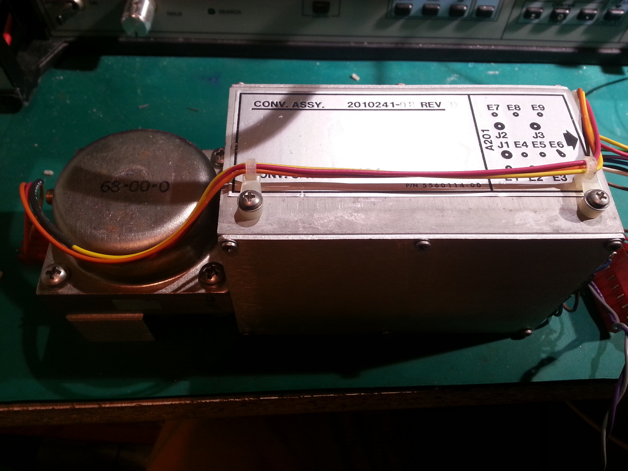
As I said, it is not the same part number as the one I have (2010241-08 vs. 2010241-09 in my unit), however, this replacement unit seems to work fine, and now, the sensitivity is way better than before: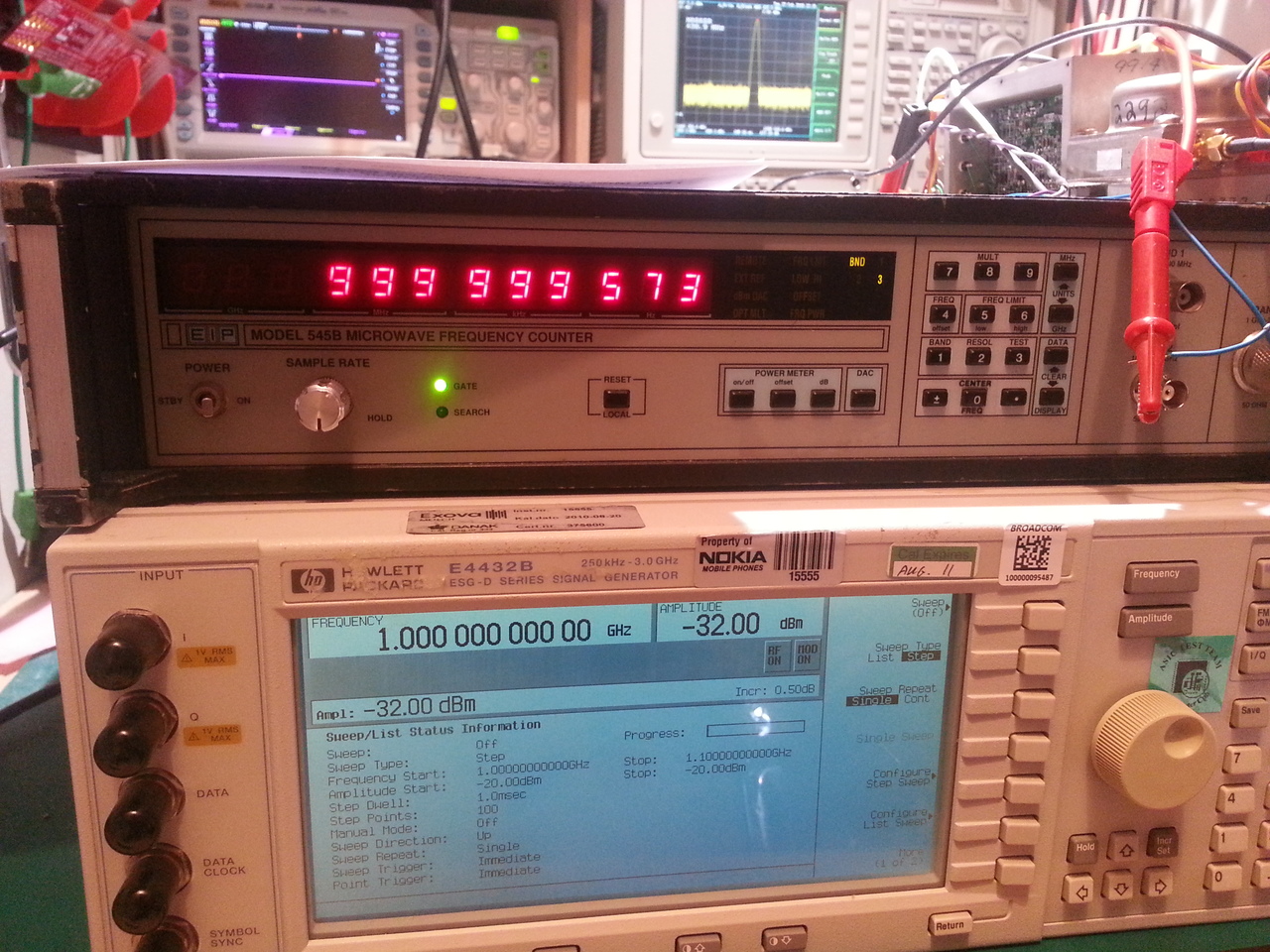
Note that this later picture has been taken without doing any king of calibration of the YIG fiter...
But, as I am a bit stubborn, I still want to investigate more what's wrong with my A203 unit, and thus better understand how it works.The SRD is obviuosly part of the microwave circuit, I assume is located on LO side of ceramic microcircuit at opposite side of directional coupler, I barely see, on your photo, a complex microwave circuit with inductances, stubs, capacitors, the SRD diode is located here.
Nothing is obvious for me :-) I find hard to recognize the components on the ceramic microcircuit, so I'm sure of nothing.
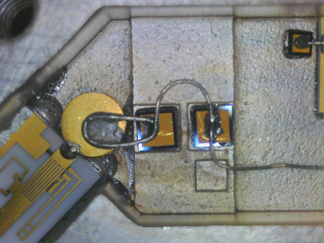
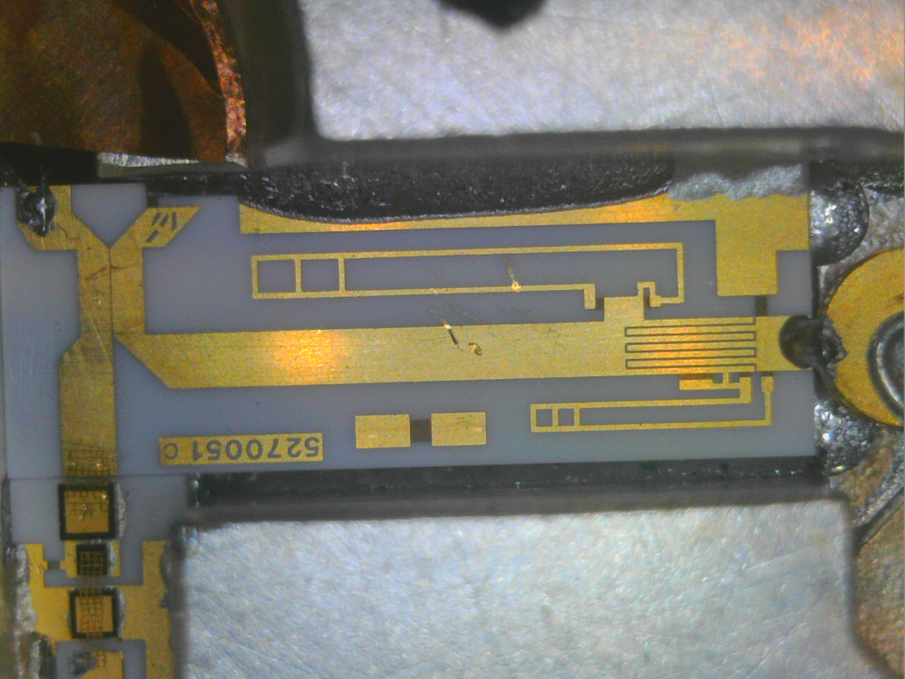
For the pleasure, here are closer views of the ceramic microcircuit (between the VCO output and the directional coupler):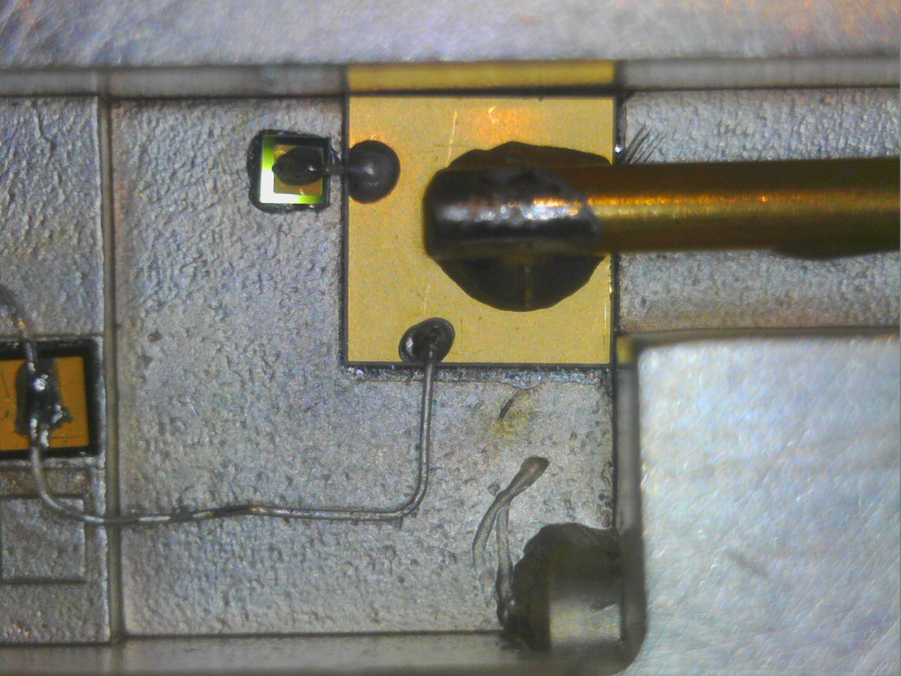
Coupling side of the coupler receive the comb signal from LO and is terminated at ground side with a resistor, probably 50 ohm and a laser trimmed capacitor.
LO signal is directionally injected to main side of coupler toward the mixer diode, also on this main side of coupler pass the YIG filtered input signal to mixer.
Just after the mixer there are two small wires for IF output signal (127MHz).
Yes all these makes much more sense for me now. I may try to draw a schematic of this microcircuit, just for the sake of completeness...This resistor is connected in series with a inductance to the RF power transistor collector terminal to feed supply current from the +12V power rail, heating of resistor is NOT normal at 150 degrees level, measure the voltage drop on resistor and the resistance value, it should be 10 ohm.
Try to short the base terminal of 2SC2283 to ground and verify if the voltage drop on resistor goes to zero volts, shorting base to ground removes BIAS voltage from resistive divider, if the voltage drop on resistor remains high the RF transistor is probably damaged.
Yes it is a 10 ohm resistor. I'll measure the voltage across it tomorrow (or so), playing with the amp power "switch" (via I/O at address 0x1843), and I'll tweak the base term of the 2SC2283 also, and check again the max temperature it reaches (I did measure with my poor's man thermal camera, not very accurate, but very handy when fixing PCBs nonetheless).
And I still have a few tasks to do:
- calibrate the YIG filter (but I can only reach 3GHz with my E4432B),
- calibrate the power meter (which will be way easier now that I have a decent (Gigatronic) power meter with a probe that goes up to 20GHz,
- finish fixing the firmware for the digits resolution default setting (as well as the 'Offset' led indicator that remains on even if I did fix the actual frequency offset value at startup).
David
-
I have removed the VCO board of my broken unit and begun to reverse engineer the schematic (not yet entered in kicad however).
The board looks like this: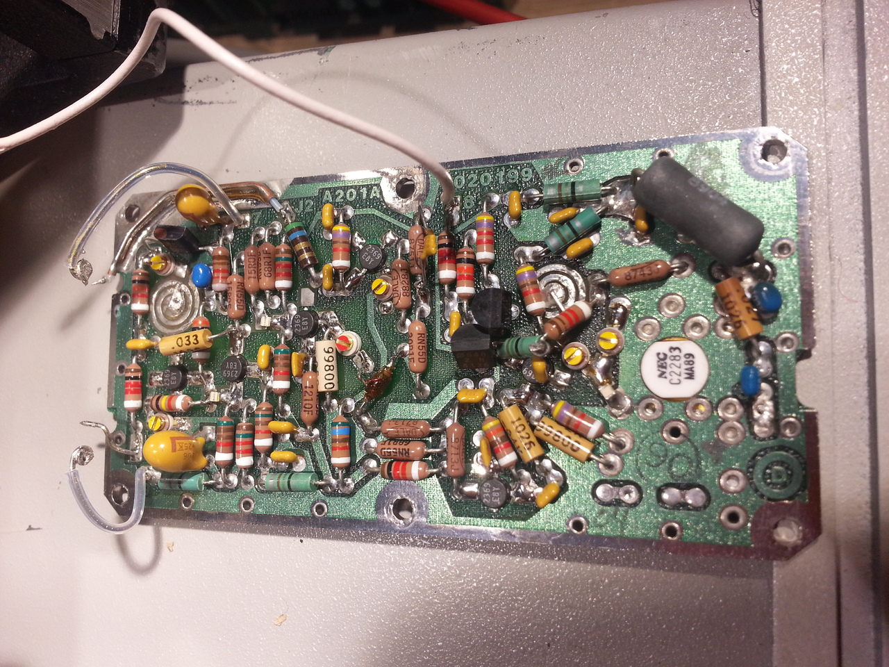
I have not found any obvious culprit for now for its poor behavior (the output transistor, SC2283, looks OK with a simple diode measurement), but I have found an interesting thing:
on this version of the VCO, the big 3W resistor is a Dale RW69 V220: a military version, 22ohm, capable of holding 350°C according to the datasheets!
So it might be normal it's getting pretty hot when the output power amplifier is on.
David
-
SRD harmonic generator is in the blue ring
-
Hi Everybody,
Thanks Douarda for this passionating dive into EIP545B!
I'm also interested with activating the power meter in mine but I don't know how to proceed. When I'm trying to turn on the power meter it says 'Error 13' which I believe means the option is not installed?
However I'm facing to a more serious error since this morning as my counter is saying Error 40 at every startup now and can't count above 1Ghz on Band 3. This suddenly happened. I did all the check on A107 but I've found nothing wrong. The only wrong thing I've found is there is no ramp on J7 pin 2 while this one is there when I'm entering in Test 06.
Does anybody knows what Error 40 is? Sometime when I turn it on ti says Error 32 but right after it switch to Error 40. If I understood correctly Error 32 is related to PROM check (U12?) but I don't know what Error 40 is. Any help will be really appreciated
Thanks! -
douardda, Did you get the YIG working in your counter? If not, I have a 545 that I got in pieces and I have an extra YIG oscillator and it appears to be in good condition. I think it may have option2 in it as well.
-
Hi All,
I've had a look at EIP 575 Service Manual and found Error 40 code means DAC table Error. Thus, if this Service Manual can be used for my 545B I'll be able to repair it. At least I have to dig a bit more onto A107 board now.
Cheers -
I've had a look at EIP 575 Service Manual and found Error 40 code means DAC table Error.
"DAC Table Error" is apparently an access problem to calibration data stored in A105 EEPROM, Error 32 is also suspicious related. Check all power supply voltages on main board, not directly on power supply board, often there are problem on connectors contacts to board edges.
Also check for possible data/address BUS overloads from PIA chips (68B21).QuoteThus, if this Service Manual can be used for my 545B I'll be able to repair it. At least I have to dig a bit more onto A107 board now.
Yes, this manual is usable. -
douardda, Did you get the YIG working in your counter? If not, I have a 545 that I got in pieces and I have an extra YIG oscillator and it appears to be in good condition. I think it may have option2 in it as well.
Hi, yes I have the power meter working. I made some hardware modification on A107: add an AD7524 (U12) , removed R39 and installed a detection diode (I used a QSCH1245 instead of the original FH1100).
But I did nothing on the firmware side: the power meter code was already included in the CPU main EPROMs.
I have not yet made the required calibration for the power meter to be really usable. For now I'm installing a better OXCO in the EIP before doing a complete calibration of the unit (up to rather low frequencies for now, since I cannot generate signals above 3GHz).
Note: I described this in part 2 of my series on my 545B https://whatever.sdfa3.org/eip-545b-rf-frequency-counter-part-2.html
David -
douardda, Did you get the YIG working in your counter? If not, I have a 545 that I got in pieces and I have an extra YIG oscillator and it appears to be in good condition. I think it may have option2 in it as well.
Nope I could not make it work properly. I'm pretty sure I have a problem on one of the 2 boards in this unit (in addition to the loose YIG sphere) so in the meantime, when I found a replacement A201 unit at decent price on eb, I bought it. So I've put this repair aside for now.
David
-
Hi HighPrecision,
Thanks a lot for those precious information! I'll let you know how it goes!
Thanks also David for the information about the power meter. On mine the option is not included, but I would say I have more urgent things to do on this equipment now. -
douardda, Did you get the YIG working in your counter? If not, I have a 545 that I got in pieces and I have an extra YIG oscillator and it appears to be in good condition. I think it may have option2 in it as well.
Hi, yes I have the power meter working. I made some hardware modification on A107: add an AD7524 (U12) , removed R39 and installed a detection diode (I used a QSCH1245 instead of the original FH1100).
Hi Douardda, I was just wondering if you've removed R40 as well? Indeed, according to the schematic of Option 02, the resistor is removed as well.