Normally I avoid buying lemons by checking things out here first. But I guess this is too new. I decided to take a chance because Korad made things right on the KA3005 design that failed on Dave a while ago. I don't know that I'll ever have a need for it, but I bought the programmable version. It was only $20 more for that option, so what the heck.
It arrived today, and here it is in pictures:

It comes with a USB cable and one pair of really cheesy leads (also a driver disk, thin manual and power cord, not shown. The manual is better than many, but still Chiglish.)

Inside there's a fair bit of empty space. I assume this must be necessary for adequate cooling around that transformer?


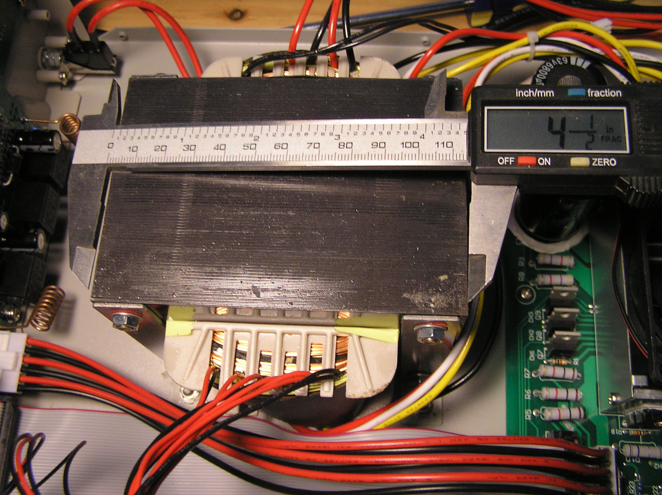
The transformer core is about 4-1/2" x 3-3/4" x 3-1/4". Other than that I can't tell you anything about it -- there's no printing on it whatsoever on any side.
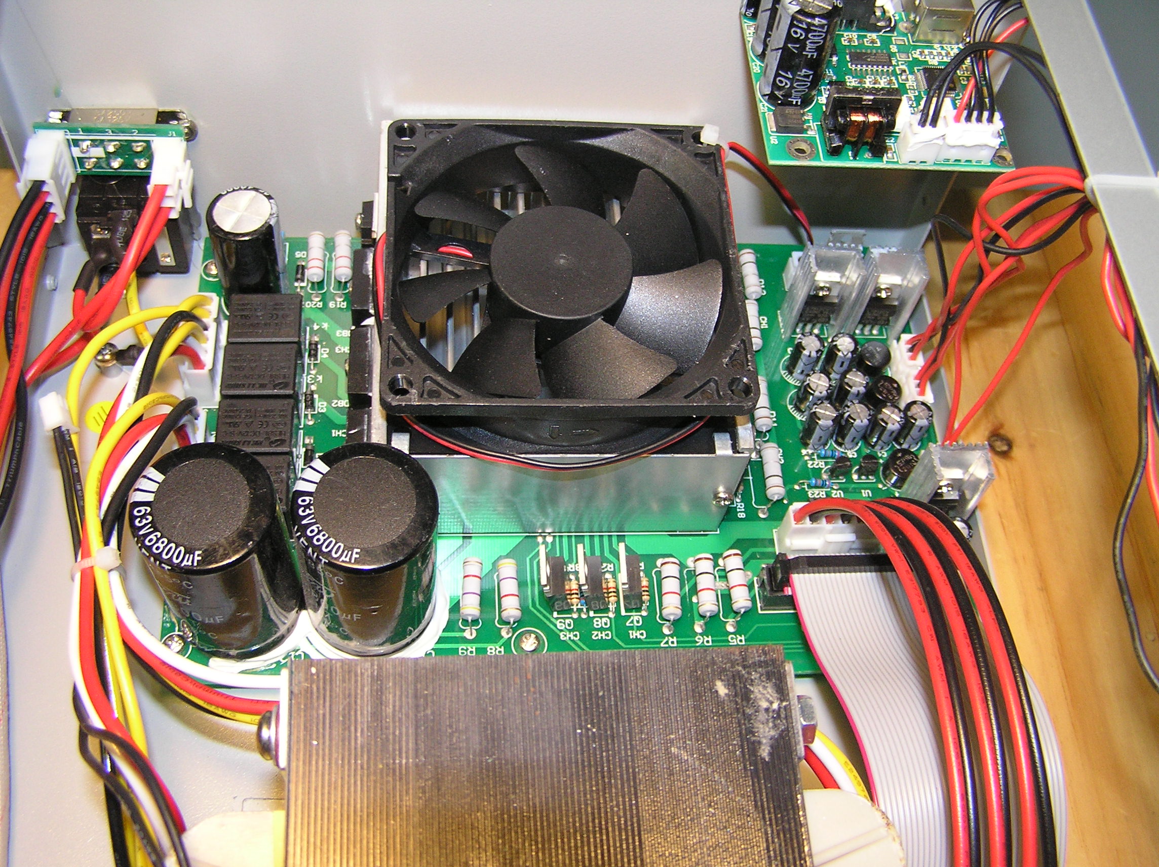
The power board is behind the transformer, dominated by a giant heat sink and fan. The little board above handles the programming communications, with both serial and USB ports.
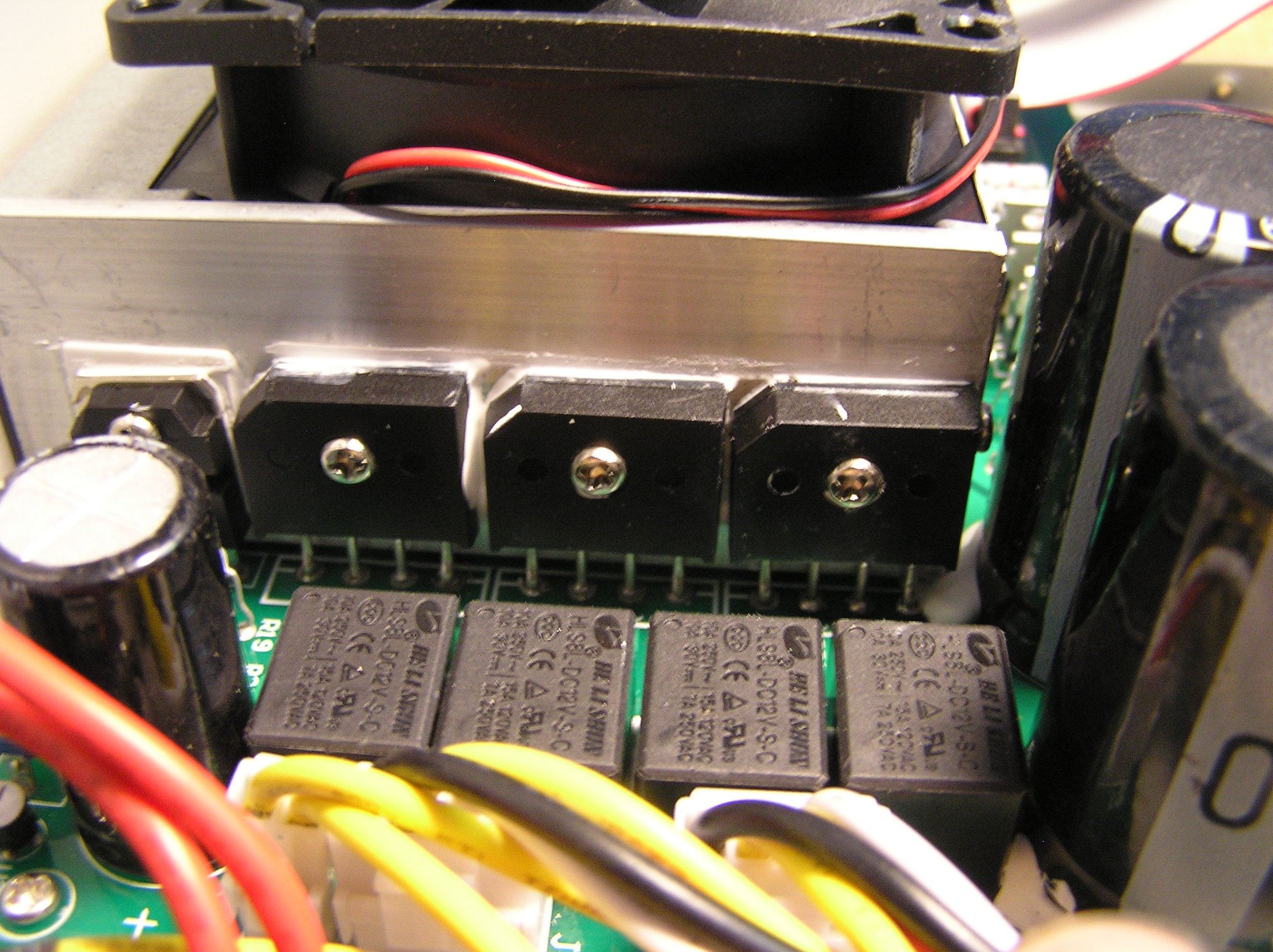
Each side of the heatsink features a row of four large semiconductor devices well bedded in thermal paste. There's also 3 TO-220 devices with individual heatsinks on the right. They are not secured to the board, relying on the device itself for support. I'm not too happy about that, but other than that the boards seem well made.

I'm not sure what exactly these devices are, there's no ID on the chips. 5 of them have 3 terminals, 3 of them have 4 terminals. At a guess, I'd say IGBTs and bridge rectifiers, but I didn't try tracing anything out:
The fan blows down on the heatsink. The fins run fore-and-aft, up against the rear exhaust vents. The front of the heat sink has been blanked off with a metal plate to ensure all air goes out the exhaust. The fan is variable speed. It doesn't run at all when no current is flowing and ramps up when the PSU is delivering power. I don't know if I ever taxed things enough to hit full speed, but what I've heard so far is very quiet. (BTW: the beeps when a button is pushed are equally unobtrusive).

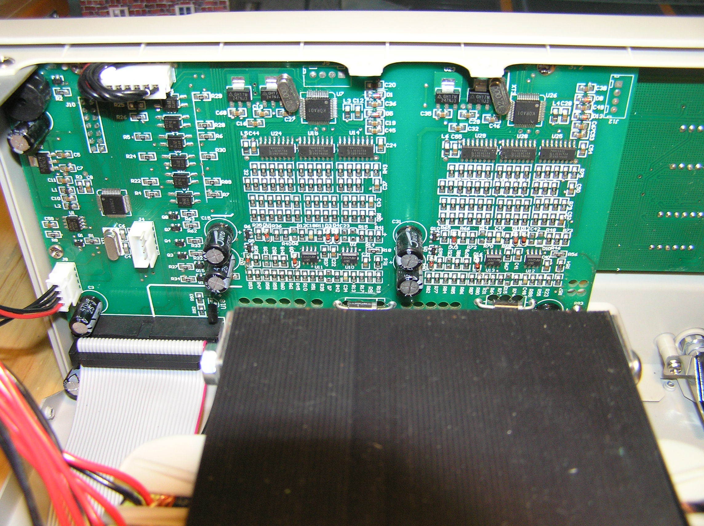
The brains of the thing are mounted to the back of the front panel. Mostly a whole lot of smd devices, but there's also an unoccupied 4-pin header. Jtag?
It comes with binding posts, which I like. The holes are a bit smaller than I'm used to though and they didn't bother to orient the holes in any particular direction on assembly! Personally, I think the holes should be aligned vertically rather than pointing at the adjacent post.
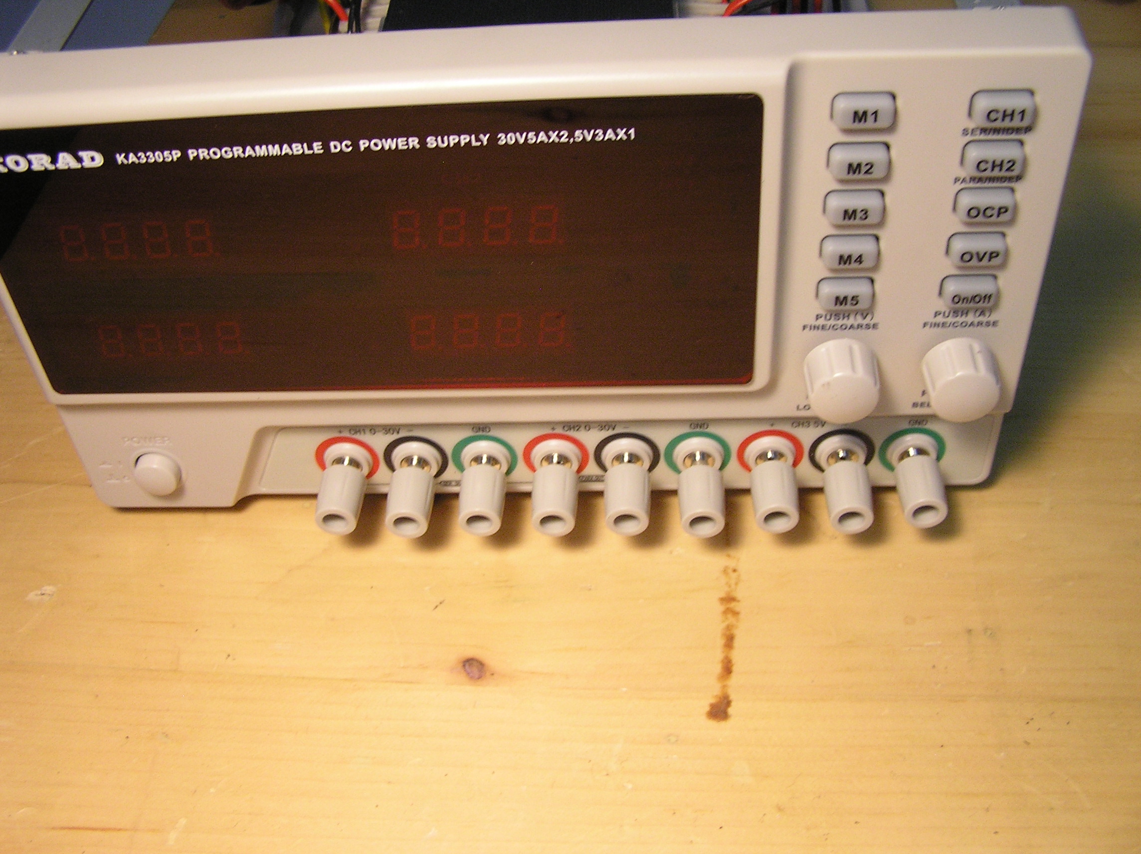
Fortunately, the posts are secured with screws to the control board (J6 to J17), so it was easy to align them all properly while things were apart. I'm still debating whether or not I should drill out the holes a bit larger though:

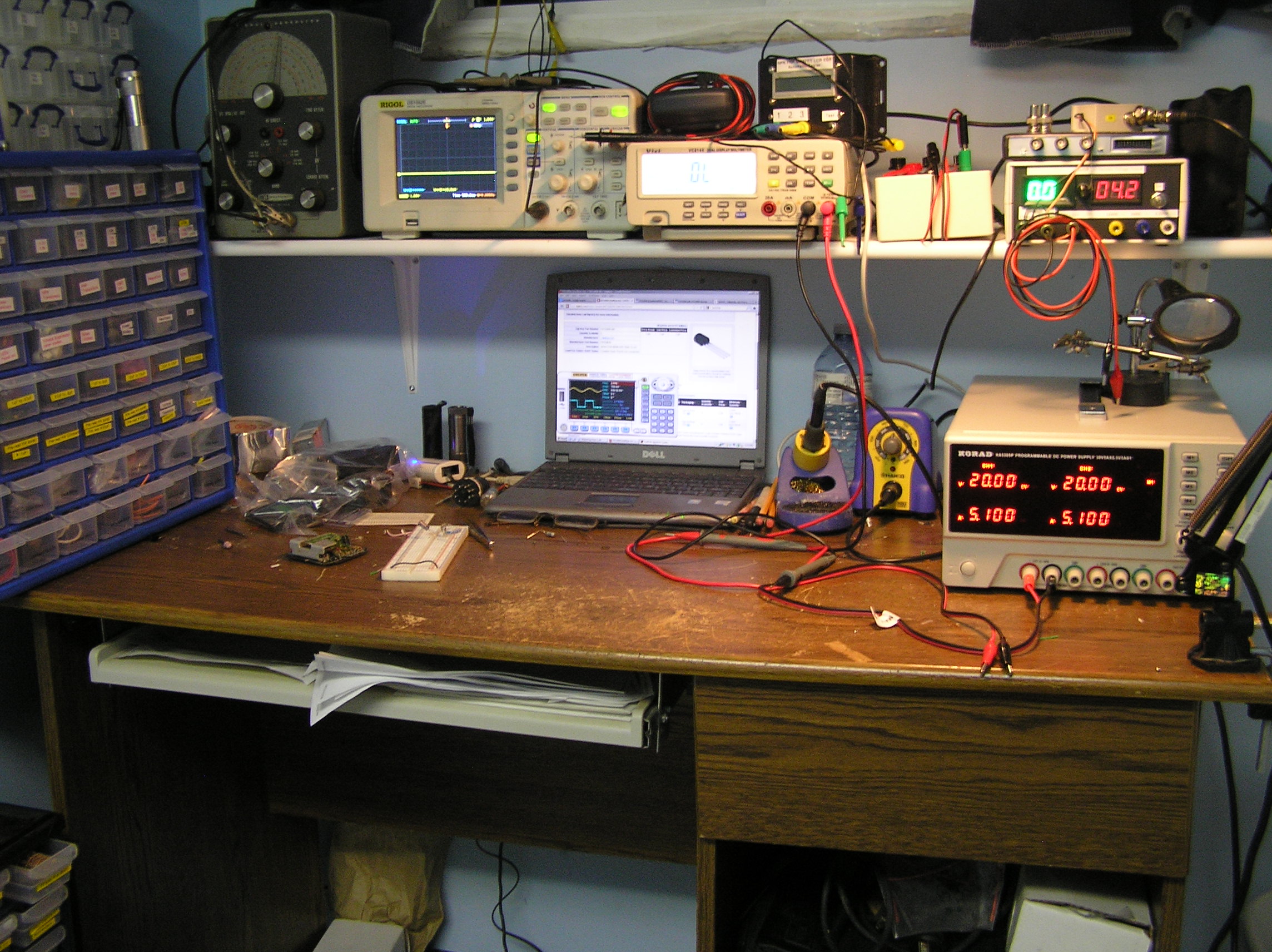
Looking at pictures on a website, I did not realize that the footprint was so damn big! It takes up a fair bit of real estate, which as you can see is at a premium in my little corner.
So, how does it work?
It seems to be fine with a dead short across the terminals. It survived the "welding test". So hopefully it has whatever improvements that Korad made to the one Dave tested. I don't have a fancy programmable load like Dave, so I tried to load it up with a carbon pile battery load tester. Now, that thing is built to measure hundreds of amps at 12v, not 5 or 10 amps at 30 or 60 volts. The adjustment is just too coarse for any semblance of precision, so my results may not be completely accurate.
That said, I could not get it to deliver more than 4 amps at 62 volts (serial mode*). If I tweaked the carbon pile a touch more, the current jumped to 5.1 amps, but the voltage dropped to 48 volts. A touch more and the current remained at 5.1a while the voltage dropped even further (sometimes down under 2v), so it looks like the current was being actively limited. I'm going to have to find a more suitable load for this test. I had similar difficulties in parallel mode. It will deliver 10.2 amps though.
The fixed 5v channel has an open circuit voltage of 4.997, which drops to 4.927 under a 1 amp load (5 ohm power resistor). The 5 volt channel is always on, unlike the two variable output channels. Both variable output channels are controlled by a single on/off switch. The display shows the set current and set voltage for each when the switch is "off" and the actual delivered values when the switch is "on", unless you are actively changing a value while powering something, in which case it temporarily reverts to displaying the set point.
In serial and parallel modes, channel 1 is slaved to channel 2, so changing the setting of channel 2 automatically changes channel 1 to the same value. Channel 1 cannot be changed independently in those modes. The display behaves a bit differently too: when actively changing the settings, the channel 1 display will continue to show the actual output while the channel 2 display shows the set points.
Changing the setpoints is not quite as simple as twirling a mult-turn pot. First you push the button for the channel you want to change. Then you push the voltage or current knob until the desired digit is flashing, then you turn the appropriate knob to change the digit. The knobs have a nice detent at each change of digit, but can revolve infinitely. As a digit passes 9, the next most significant digit is incremented. So if you are adjusting the left-most digit, the knob is a very coarse adjustment, but the adjustments are progressively finer if you choose to adjust a digit to the right. EG: Adjusting the leftmost voltage digit from 10.81 will increase to 20.81 then 30.81. But if you are adjusting the first digit to the right of the decimal, it will increase to 10.91, 11.01 etc up to 30.91. If you need the full 31 volts, you have to then switch to adjusting the right most digit. Clear as mud?
One other complication: the adjustment mode times out fairly quickly when actively delivering power. Once it times out, you have to go through the whole rigamarole again to continue any adjustments. A good idea in principle, but in practice it would be nice if the delay was a bit longer.
The system is cute, but a bit complicated. It would be easy to accidentally crank up the voltage or current too high for the circuit under test. However, there are both over-current protection and over-voltage protection features. It took me a bit to understand how they work, but they can be thought of as a kind of a customized fuse. You can set a limit for the maximum currents and maximum voltages that each channel can deliver, separately from the normal adjustment. For example, one might set the OVP to 14.5 volts when working on an automotive device so that you cannot accidentally crank the voltage up to a damaging level. If you subsequently try to exceed 14.5 volts, the PSU will shut down. Similarly, you can set current limits. Each channel can have different limits provided you are not in Serial or Parallel mode, in which case the Channel 2 limits apply. (There is no OVP or OCP for channel 3 though).
There is also a "lock" feature that locks out all control panel inputs. It's not necessary to prevent accidentally spinning an adjustment knob, but it could prevent disaster if you bumped a memory button. There are 5 preset memories. Pressing M1 through M5 switches the outputs to the values that were used when that memory was last used. Any subsequent changes while that memory position is active are automatically saved.
The displays are reasonably accurate, to within 0.006v according to my meter. Which has not be calibrated by a lab or anything. It does not go down to 0, despite the display. My uncalibrated meter still showed a few hundredths of a volt which disappears when the On/Off button is pressed. I confirmed voltage was still present by checking for current across the leads.
So in conclusion then,
Pros:
Reasonably well made for the price.
Linear.
3 channels
Lots of available power.
OVP and OCP for those times when you don't want all that power available.
Can withstand short circuits.
Quiet fan. Much quieter than any other fan in the room.
Good cooling path
Nice clear easy-to-read displays
Good tactile feel to the controls.
Multiple memories.
No noticeable heat to the case when loaded.
Binding posts (as opposed to recessed jacks)
Unobtrusive beeps.
Cons:
Very large footprint.
A single set of cheesy leads with a 3 channel PSU?
Complicated adjustment procedure.
Short time-out when adjusting.
Channel 3 not switched
Unknown components when it comes time to repair things.
Some heat sinks not secured to a fixed point.
Did I mention how big it is?
To Do:
Find a more suitable load to test the extremes.
Try out the software and programming capabilities.
Figure out a better place to put it.
*A note for the uninitiated: Serial mode is simply connecting the two channels in series, internally connecting Channel 1 negative to Channel 2 positive. Available voltage doubles. Alternatively, either Channel 1 negative or Channel 2 positive can be connected to the circuit ground, turning the Channel 1 positive into a + voltage supply and the Channel 2 negative into a - voltage supply for things like op-amp circuits. Parallel mode connects the positives together and the negatives together, making a single channel with twice the available current.


